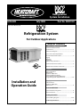
1
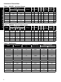
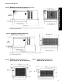
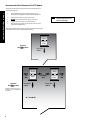
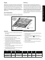
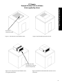
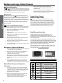
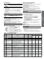
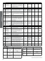
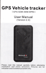
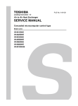
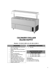
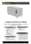
Refrigeration
System Installation
H-IM-82B
July 2008
Part No. 25001901
Replaces H-IM-82A (6/06)
Refrigeration System
For Outdoor Applications
Table of Contents
1. Owner's Installation Instructions
Performance/Electrical Data
Specifications.....................................................................................2
Dimensional Diagrams...................................................................3
Space and Location Requirements
Recommended Unit Placement..................................................4
Rigging
Mounting
Inspection
General Safety Information..........................................................5
Standard Installation Procedure.................................................6
Outdoor Unit Installation Instructions.....................................7
2. Freezers
Service Information
Maintenance
Sequence of Operation
Freezer System Pre-Setpoints
Electric Defrost Sequence of Operation
Programming Electric Defrost Controls............................ 8-10
Installation and
Operation Guide
3. Coolers
Defrost Controls
Sequence of Operation
Maintenance................................................................................... 11
4. Service Information
System Troubleshooting Chart................................................. 12
Replacement Parts........................................................................ 13
5. Wiring Information
Electrical Wiring Diagrams...................................................14-19
6. Warranty Information ........................................................ 20
© 2008 Heatcraft Refrigeration Products LLC
Performance / Electrical Data
Table 1. COOLERS – Air Defrost Systems
1. Owner's Operating Instructions
Model
BTUH @ 95˚F
35˚F Box Temp 38˚F Box Temp
PTT047H2B
PTT063H2B
PTT072H2B
PTT099H2B
PTT099H2C
PTT128H2B
PTT128H2C
4,980
6,680
7,630
10,490
10,490
13,570
13,570
5,300
7,100
8,060
11,340
11,340
14,520
14,520
Voltage
208-230/1/60
208-230/1/60
208-230/1/60
208-230/1/60
208-230/3/60
208-230/1/60
208-230/3/60
MCA MOPD
Unit Evap
Plug
Amps CFM Supplied
8.6
9.8
10.9
17.1
14.7
20.1
14.1
7.3
9.9
9.3
14.7
13.3
17.2
12.8
15
15
15
20
20
30
20
350
550
500
875
875
825
825
No
No
No
No
No
No
No
Matching
NEMA
Receptacle
—
—
—
—
—
—
—
Fig.
B
B
B
C
C
C
C
Table 2. FREEZERS – Electric Defrost Systems
Model
PTT021L6B
PTT031L6B
PTT044L6B
PTT052L6B
PTT052L6C
PTT069L6B
PTT069L6C
BTUH @ 95˚F
-10˚F -20˚F
0˚F Box Temp Box Temp Box Temp
2,680
2,160
1,340
4,220
3,190
2,060
5,870
4,530
3,400
7,000
5,360
3,910
7,000
5,360
3,910
9,060
7,100
5,250
9,060
7,100
5,250
Voltage
208-230/1/60
208-230/1/60
208-230/1/60
208-230/1/60
208-230/3/60
208-230/1/60
208-230/3/60
MCA MOPD
7.6
13.8
15.9
18.1
15.0
23.8
15.9
15
15
20
20
15
30
20
Unit Evap
Plug
Amps CFM Supplied
6.5
11.6
13.3
15.5
11.3
20.0
14.2
350
550
520
900
900
875
875
No
No
No
No
No
No
No
Matching
NEMA
Fig.
Receptacle
———————-
Table 3. Specifications
Model
Refrigerant
PTT047H2B
PTT063H2B
PTT072H2B
PTT099H2B
PTT099H2C
PTT128H2B
PTT128H2C
22
22
22
22
22
22
22
Refrigerant Charge
Total Heat of
(oz.)
Rejection (BTUH)
Approx. Net Weight
lbs.
kg
COOLERS
27
29
32
47
47
52
52
6,700
8,700
9,700
16,800
16,800
18,000
18,000
192
207
211
270
265
290
285
100
100
100
127
127
127
127
4,300
6,300
9,900
10,900
10,900
15,300
15,300
213
221
225
275
270
280
275
100
100
100
127
127
127
127
FREEZERS
PTT021L6B
PTT031L6B
PTT044L6B
PTT052L6B
PTT052L6C
PTT069L6B
PTT069L6C
404A
404A
404A
404A
404A
404A
404A
26
28
29
45
45
47
47
B
B
B
C
C
C
C
Dimensional Diagrams
1. Owner's Operating Instructions
Figure A. Medium Cabinet Dimensions without weather hood Models PTT 021, 031, 044, 047, 063, 072
*
25" x 25" panel opening required for evaporator section of medium cabinet sizes.
* 21.5" with weather hood.
Figure B. Large Cabinet without weather hood
Models PTT 052, 069, 099, 128
*
25" x 38 1/2" panel opening required for evaporator section of large cabinet sizes.
* 23.5" with weather hood.
Figure C. Medium Cabinet with weather hood Models PTT 021, 031, 044, 047, 063 and 072
Figure D. Large Cabinet with weather hood Models PTT 052, 069, 099 and 128
Recommended Unit Placement For PTT Models
Some general rules for the evaporator section placement which
must be followed are:
1. Owner's Operating Instructions
1.
Ensure that the structural integrity of the box can withstand the weight of the top mounted equipment.
2.
The air pattern must cover the entire room.
3.
NEVER locate the evaporator section over doors.
4.
5.
Location of aisles, racks, etc. must be known.
Never remove or unlock any panel cam-locks to install top mounted equipment.
NOTE:
Always avoid placement of
units directly above doors
and door openings.
The size and shape of the storage will generally determine the type
and number of units to be used and their location.
Evaporator
Section
Compressor
Section
Top View
One
System
Evaporator
Airflow
Evaporator
Section
W
Min.
Top View
Two
Systems
Compressor
Section
Evaporator
Airflow
Multiple units must be spaced
properly to provide adequate air
circulation.
W = Unit Width
Evaporator
Section
2 x Width
Min.
Compressor
Section
Evaporator
Airflow
W
Min.
Mounting
Rigging holes are provided on all models. Caution should be
exercised when moving these units. To prevent damage to
the unit housing during rigging, cables or chains used must
be held apart by spacer bars. The mounting platform or base
should be level and located so as to permit free access of
supply air. The unit weather hood may be removed for the
rigging process. The condensing unit cover (wrapper) should
be left in place.
The system requires an opening in the ceiling to the
dimensions stated on page 3. Mounting rails are located
at both ends of the chassis. Mounting rails may be used to
attach unit to ceiling. Through-bolts should be insulated or
non-conductive to prevent sweating. The chassis is weather
stripped around the air grille and will seal to the box roof.
The trim ring (shipped loose), when provided, should be
installed around the air diffuser when secured with the
hardware provided. Be sure to adhere to your local standard
construction codes.
Access Requirements
1. Owner’s Operating Instructions
Rigging
Provide adequate space at the compressor end of the unit for
servicing. Provide two (2) feet of space above unit for service.
Trim Pieces (4)
Overlap as Shown
Trim Ring
Installation
Detail
Ceiling of Walk-in.
Evaporator Grill
Self Drilling Screw
Inspection
General Safety Information
1. Each shipment should be carefully checked against the
bill of lading.
1. Installation and maintenance to be performed only by
licensed contractor.
2. The shipping receipt should not be signed until all items
listed on the bill of lading have been accounted for.
2. Ensure that the structural integrity of the box can
withstand the weight of the
(See page 2, Table 3 for
unit weights).
3. Check packaging for signs of damage.
4. Any shortage or damages should be immediately
reported to the delivering carrier.
3. Avoid contact with sharp edges and coil surfaces.
They are a potential injury hazard. Wear gloves during
moving and rigging.
5. Damaged material becomes the delivering carrier’s
responsibility, and should not be returned to the
manufacturer unless prior approval is given to do so.
4. Make sure all power sources are disconnected before
any service work is done on units.
6. When unpacking the system, care should be taken to
prevent damage.
7. Avoid removing the shipping base until the unit has been
moved to the final destination.
8. Complete warranty return card for each unit and mail to
Heatcraft Refrigeration Products.
Table 4. Control Factory Default Settings
PTT
Models
Temperature
Set Points
Defrost
Start Times
Defrost Duration
(Maximum)
Drip
Time
Fan
Delay
Defrost Termination
Set Point
Cooler Models
All cabinet sizes
35˚F
Every 3 hours of
compressor run time
60 min.
–
–
38˚F
Freezer Models
Med. & Lg. cabinet
-10˚F
4 / day
40 min.
2 min.
2 min.
65˚F
The Outdoor
comes standard with the
following additional components:
1. Owner's Operating Instructions
•
•
•
•
Crankcase Heater
Drain Line Heater
Weather Hood
Fan Cycling
(Pressure on 1 fan models, Pressure and Ambient on 2 fan models).
Standard Installation Procedure
PTT Models
For outdoor use
1. Provide a 25" X 25" (medium cabinet) or
25" X 38.5" (large cabinet) opening in the
roof of walk-in cooler or as specified by the
panel manufacturer.
2.
Apply silicone caulk around the perimeter of roof
opening. Place the curb on roof of cooler. It is recommended that the curb be fastened to
the roof panels using non-conductive bolts or
insulating the bolt heads. Bolt heads should be
countersunk or low profile to prevent contact with
the
system. (See Figure 1, page 7) Check the
top of the curb with a level.
units require
a surface that is within 1° of level or better and no
more than a 5/8" drop per 3 feet
(17mm drop per meter).
3.
Install the membrane onto the roof of the box and
over the curb. Fasten to roof per panel
manufacturer's instructions. The membrane
material should be slit over the evaporator grill
opening the flaps allowed to drape into the hole
2" - 4". (See Figure 2, page 7) Care should be taken
during the membrane installation to prevent
bunching or folding which could affect the gasketto-curb sealing or trap rainwater adjacent to the
curb.
4. Remove the weather hood from the
system.
The compressor compartment cover(s) should be
left in place during lifting/rigging.
5. Place
system onto curbing and center over
opening in roof box. (See Figure 3, page 7)
6.
It is recommended that the
system be
secured to the curb with wood screws. Seal
the screw heads as necessary to prevent moisture from entering beneath the membrane.
Additional caulk may be applied around the
perimeter of the evaporator box gasket. The
compressor compartment should not be caulked.
7. Install trim pieces (if used) around the ceiling
opening in cooler.
Condensate Drain
Outlet Location
8. Remove compressor compartment cover for
access to electrical box.
9. Connect power wiring in accordance with all
applicable building and electrical codes.
10. Reinstall condensing unit cover(s).
11. Reinstall the protective weather hood.
(See Figure 4, page 7)
12. Apply power and check for proper operation.
Drain Line
A condensate drain outlet is located on the side of the
compressor compartment. Field piping may be connected
to the outlet provided it is adequately sloped and heated
for freezing weather conditions. There is a drain line "P" trap
located in the PTT unit.
General Safety information:
Do NOT lift the
by the weather hood.
This product is not designed to be transported while
installed or operating.
1. Owner's Operating Instructions
PTT Models
Example Outdoor Curb Installation
(Curb supplied by others)
This area of
curb may be solid.
Figure 1. Curb placed on roof of walk-in cooler.
Figure 2. Roof membrane placed over curb.
Note: Do not caulk
around the base of compressor compartment.
Figure 3. PTT unit placed on roof of walk-in color.
(see rigging instructions).
Figure 4. Weather hood installed after electrical service
connection.
Medium and Large Cabinet Freezers
Service Information
All
units are designed for maximum durability, reliability and
simplicity.
comes to you ready for operation, fully charged and
with all controls preset at the factory. The following information is
provided as an aid in the event that service is required.
Maintenance
2. Freezers
The evaporator section of a
system should be checked at
least once for proper defrosting because the amount and pattern
of frosting can vary greatly. The frost build-up is dependent on
the temperature of the room, the type of product being stored,
how often new product is brought into the room and percentage
of time the door to the room is open. It may be necessary to
periodically change the number of defrost cycles or adjust the
duration of defrost.
System Standard Maintenance Guidelines
After first year of operation and under normal usage, maintenance
should cover the following items at least once every six months:
1. Check and tighten ALL electrical connections.
2. Check all wiring and insulators.
3. Check contactors for proper operation and for worn
contact points.
4. Check all fan motors. Tighten motor mount bolts/ nuts
and tighten fan set screws.
5. Clean the condenser coil surface.
6. Check the operation of the control system. Make certain
all safety controls are operating properly.
7. Check that all defrost controls are functioning properly.
8. Clean the evaporator coil surface.
9. Clean the drain pan and check the drain pan and drain line for proper drainage.
Refrigeration Sequence of Operation
3.
The temperature/defrost control energizes the
compressor contactor, starting the compressor and
condenser fan(s).
4.
Freezer evaporator fans will be energized by the
temperature/defrost control when the coil temperature
reaches 35°F or fan delay time has elapsed.
Freezer Defrost Control - Medium & Large Cabinet
freezer units come factory equipped with an electronic
temperature/defrost control. There are 2 different models of
electronic control used and it is important to determine which
one is present on your unit before altering any factory settings.
Please refer to the picture of the controller display on this page
to determine the model used. Instructions for any necessary
reprogramming are included in this manual on pages 8-10.
Dixell Electronic Controller
The Dixell XR-60CX and the Dixell XR-60C are fully
configurable electronic refrigeration controllers. All
parameter values are reprogrammable and are stored in the
non-volatile memory.
The controllers use two levels of programming that can be
accessed through the keypad. The first level is the user level.
It gives access to six settings; temp. differential, defrost cycle
intervals, defrost termination temperature, draining time,
defrost fan delay, and fan stop temperature.
The second level is the service level. It allows access to all
other parameters. It is recommended that changes in this
level be made only by a qualified technician.
Front Panel Commands
1. Power is provided to the temperature control, compressor contactor and cooler evaporator fans.
2.
The temperature controller closes and energizes the
compressor contactor, starting the compressor,
evaporator and condenser fan(s).
3.
When the system reaches the desired box temperature,
the temperature control will de-energize the compressor
contactor. Evaporator fans will continue to operate at
this point.
4.
When the fixture temperature rises above the set point
and minimum off-time has elapsed, the temperature
control will close and re-energize the compressor contactor.
XR-60CX Controller
Use of LEDS
Each LED function is described in the following table.
LED
Electric Defrost Sequence of Operation
for Freezers
1. During normal operation, at the preset time intervals, LED MODE
FUNCTION
ON
Compressor enabled
Flashing
the temperature/defrost control will de-energize the
compressor contactor and evaporator fans and energize
the defrost heaters. These functions are controlled
through relays on the controller.
2.
XR-60C Controller
ON
When the coil has defrosted fully and has reached the
preset coil temperature (as sensed by the coil
temperature sensor) the defrost heater de-energizes
and the fan delay and drip sequences begin.
Flashing
- Programming Phase (flashing with )
- Drip time in progress
ON
Fans enabled
Flashing
-Programming Phase (flashing with )
- Anti-short cycle delay enabled
Defrost enabled
ON
Fans delay after defrost in progress
(60CX only)
A temperature alarm occurred
HOW TO SEE THE SETPOINT
1. Push and immediately release the SET key:
the display will show the Set point value.
HOW TO CHANGE THE SETPOINT
1. Push the SET key for more than 2 seconds to change the
Set point value;
2. The value of the set point will be displayed and the LED
starts blinking;
3. To change the Set value push the UP or DOWN arrows
within 10s.
4. To memorise the new set point value push the SET key
again or wait 10s.
HOW TO START A MANUAL DEFROST
Push the DEF key for more than 2 seconds
and a manual defrost will start.
HOW TO CHANGE a parameter value
To change the parameter’s value operate as follows:
1. Use “UP” or “DOWN” to change its value.
2. Press “SET” to store the new value and move to the
following parameter.
To exit: Press SET + UP or wait 15s without pressing a key.
NOTE: the set value is stored even when the procedure is
exited by waiting the time-out to expire.
THE HIDDEN MENU
The hidden menu Includes all the parameters of the instrument.
HOW TO ENTER THE HIDDEN MENU
1. Enter the Programming mode by pressing the Set + DOWN key for 3s (LED 1 and start blinking).
2. When a parameter is displayed keep
pressed the Set + DOWN for more than 7s. The Pr2 label will be displayed immediately followed from the HY parameter.
NOW YOU ARE IN THE HIDDEN MENU.
3. Select the required parameter.
4. Press the “SET” key to display its value (Now only the LED
is blinking).
5. Use UP or DOWN to change its value.
6. Press “SET” to store the new value and move to the
following parameter.
To exit: Press SET + UP or wait 15s without pressing a key.
NOTE: the set value is stored even when the procedure is
exited by waiting the time-out to expire.
HOW TO SEE THE alarm duration and MAX (min)
TEMPERATURE
If the alarm LED is on, an alarm has taken place.
To see the kind of alarm, the max (min) reached temperature
and alarm duration do as follows:v
1. Push the Up or Down key.
2. On the display the following message is shown::
“HAL” for high temperature alarm (“LAL” for the
minimum allarm), followed by the Maximum
(minimum) temperature.
Then the “tiM” (tiMe) message is displayed, followed by
the “Duration” in h.mm.
3. Then the instrument displays the temperature once
again.
NOTE1: if an alarm is still occurring the “tim” shows the
partial duration.
NOTE2: the alarm is recorded when the temperature come
back to normal values
HOW TO RESET a recorded alarm OR ONE THAT IS
STILL OCCURRING
1. Hold the SET key pressed for more than 3s, while the
recorded alarm is displayed. (the rSt message will be
displayed)
2. To confirm the operation, the “rSt” message starts
blinking and the normal temperature will be displayed
DEFAULT PARAMETER SETTINGS
Label Characteristic
Description
Menu/User
Level
Hy
LS
US
Ot
OdS
AC
COF
Default Settings
Low
Temp.
Medium
Temp.
High
Temp.
LS ~ US
-10
34
38
Pr1
1~ 45
3
3
3
Pr2
-67 ~ SET
-23
25
33
Pr2
SET ~ 302F
37
40
45
Pr2
-21~21
0
0
0
Pr2
0 ~ 255
minutes
0
0
0
Pr2
0 ~ 50
minutes
4
4
4
Pr2
0 ~ 255
minutes
6
6
6
Regulation
SEt Set Point
(0,1 ÷ 25,5°C / 1÷255 °F) Intervention
differential for set point. Compressor
Differential
Cut IN is Set Point + differential (Hy).
Compressor Cut OUT is when the
temperature reaches the set point
(- 50°C÷SET/-58°F÷SET): Sets the minimum
Minimum set point
value for the set point..
(SET÷110°C/ SET÷230°F). Set the maximum
Maximum set point
value for set point.
Thermostat probe (-12.0÷12.0°C; -120÷120°F) allows to adjust
calibration
possible offset of the thermostat probe
(0÷255min) This function is enabled at
Outputs activation the initial start up of the instrument and
delay at start up
inhibits any output activation for the period
of time set in the parameter
Anti-short cycle
(0÷50 min) minimum interval between the
delay
compressor stop and the following restart
(0÷255 min) time during which the
Compressor OFF
compressor is OFF in case of faulty
time with faulty
thermostat probe. With COF=0
probe
compressor is always active
Possible
Settings
2. Freezers
Main Functions
Display
CF
Temperature
measurement unit
°C=Celsius; °F=Fahrenheit. WARNING: When
the measurement unit is changed the SET
point and the values of the parameters Hy,
LS, US, Ot, ALU and ALL have to be checked
and modified if necessary
°C = Celsius
Pr2
°F
°F
°F
Pr2
EL = electric
defrost / in
= hot gas
defrost
EL
EL
EL
Pr1
-58~122
65
65
38
Pr1
0 ~ 120
hours
6
6
6
Pr2
0 ~ 255
minutes
40
40
60
Pr1
0 ~ 255
minutes
2
2
0
°F
=Fahrenheit
Defrost
tdF
Defrost type
EL = electrical heater; in = hot gas
2. Freezers
(-50÷50 °C/ -58÷122°F) (Enabled only when
Defrost termination EdF=Pb) sets the temperature measured by
dtE
temperature
the evaporator probe, which causes the end
of defrost
Interval between
(0÷120h) Determines the time interval
IdF
defrost cycles
between the beginning of two defrost cycles
(0÷255min) When P2P = n, (not evaporator
probe: timed defrost) it sets the defrost
(Maximum) length
MdF
duration, when P2P = y (defrost end based
for defrost
on temperature) it sets the maximum
length for defrost
(0÷120 min) time interval between reaching
defrost termination temperature and the
restoring of the control’s normal operation.
Fdt Drip time
This time allows the evaporator to eliminate
water drops that might have formed due
to defrost
Fans (XR60CX only)
Fnd
Fans delay after
defrost
(0÷255min) Interval between end of defrost
and evaporator fans start
Pr1
0 ~ 255
minutes
2
2
Not
Applicable
Fct
Temperature
differential
avoiding short
cycles of fans
(0÷59°C; Fct=0 function disabled). If the
difference of temperature between the
evaporator and the room probes is more
than the value of the Fct parameter, the
fans are switched on
Pr2
0~90
10
10
Not
Applicable
FSt
Fans stop
temperature
(-50÷50°C/122°F) setting of temperature,
detected by evaporator probe, above
which fans are always OFF
Pr1
-58~122
35
35
Not
Applicable
Pr2
rE = relative
to set point
Ab =
absolute
Ab
Ab
Ab
Pr2
ALL~ 302
38
50
50
Pr2
-58~ ALu
-25
15
30
Alarms
ALC
ALU
ALL
(Ab; rE) Ab= absolute temperature: alarm
temperature is given by the ALL or ALU
Temperature alarms values. rE = temperature alarms are
configuration
referred to the set point. Temperature alarm
is enabled when the temperature exceeds
the “SET+ALU” or “SET-ALL” values
(SET÷110°C; SET÷230°F) when this
MAXIMUM
temperature is reached the alarm is
temperature alarm
enabled, after the “ALd” delay time
-50.0 ÷ SET°C; -58÷230°F when this
Minimum
temperature is reached the alarm is
temperature alarm
enabled, after the “ALd” delay time
ALARM SIGNALS
Message
Cause
Outputs
Message
Cause
Outputs
“P1”
Room probe
failure
Compressor output
according to par. “Con” and
“COF”
“LA”
Minimum
temperature alarm
Outputs unchanged.
“dA”
Door open
Compressor and fans
restarts
“EA”
External alarm
Output unchanged.
“P2”
“HA”
Evaporator probe
failure
Defrost end is timed
Maximum
temperature alarm
Outputs unchanged.
Reprinted with permission from Dixell.
10
All Cooler Models
Cooler units utilize an electronic temperature control.
The temperature may be adjusted by setting the dial. This
control is preset to provide 3 hours of compressor run time
between defrost cycles. Defrosts are temperature terminated
and cannot be reprogrammed. The temperature control
is programmed for minimum on cycle of one minute and
minimum off cycle of four minutes.
Air Defrost Sequence of Operation for Coolers
Air defrost units are preprogrammed for 3 hours of
compressor run time between defrosts. These periods are
not reprogrammable. After 3 hours, the temperature control
will turn the compressor off. When the coil temperature
reaches 38°F, the control will terminate the defrost cycle.
Room Thermostat Settings:
• Approximate dial settings of control
0 = Unit off (not an electrical disconnect)
1 = 52°F (11°C)
2 = 49°F (9°C)
3 = 45°F (7°C)
4 = 41°F (5°C)
5 = 38°F (3°C)
6 = 34°F (1°C)
NOTE: If power is interrupted to the unit during the
refrigeration off-cycle (system at temperature setpoint,
compressor off ), the thermostat will initiate an extra defrost
period approximately one hour after power is restored.
Maintenance
The evaporator section of a
system should be checked
at least once for proper defrosting because the amount
and pattern of frosting can vary greatly. The frost build-up
is dependent on the temperature of the room, the type of
product being stored, how often new product is brought
into the room and percentage of time the door to the room
is open.
System Standard Maintenance Guidelines
After first year of operation and under normal usage,
maintenance should cover the following items at least once
every six months:
1. Check and Tighten ALL electrical connections.
2. Check all wiring and insulators.
3. Check contactors for proper operation and for worn contact points.
4. Check all fan motors. Tighten motor mount bolts/nuts and tighten fan set screws.
5. Clean the condenser coil surface.
6. Check the operation of the control system. Make
certain all safety controls are operating properly.
7. Check that all defrost controls are functioning properly.
8. Clean the evaporator coil surface.
9. Clean the drain pan and check the drain pan and drain line for proper drainage.
11
3. Coolers
Cooler Defrost Control
Table 5. System Troubleshooting Chart
PROBLEM
POSSIBLE CAUSES
Compressor
1. Main switch open.
1. Close switch.
will not run
2. Fuse blown.
2. Check electrical circuits and motor winding for shorts or grounds.
3. Thermal overloads tripped.
POSSIBLE CORRECTIVE STEPS
Investigate for possible overloading. Replace fuse after fault is corrected.
3. Overloads are automatically reset. Check unit closely when unit comes back on line.
4. Defective contactor or coil.
4. Repair or replace.
5. System shut down by safety devices.
5. Determine type and cause of shutdown and correct it before resetting safety switch.
6. No cooling required.
6. None. Wait until calls for cooling.
7. Motor electrical trouble.
7. Check motor for open windings, short circuit or burn out.
8. Loose wiring.
8. Check all wire junctions. Tighten all terminal screws.
Compressor
1. Flooding of refrigerant into crankcase.
1. Check setting of expansion valves.
noisy or vibrating
2. Worn compressor.
2. Replace.
High
1. Non-condensables in system.
1. Remove the non-condensables.
discharge
2. Fan not running.
2. Check electrical circuit. Replace if motor fails.
pressure
3. Dirty condenser coil.
3. Clean.
4. System overcharged with refrigerant.
4. Reclaim refrigerant and recharge proper amount.
4. Service Information
Low discharge
1. Insufficient refrigerant in system.
1. Check for leaks. Repair and add charge.
pressure
2. Low suction pressure.
2. See corrective steps for low suction pressure.
High suction
1. Excessive load.
1. Reduce load or add additional equipment.
pressure
2. Expansion valve overfeeding.
2. Check remote bulb. Regulate superheat.
Low
1. Lack of refrigerant.
1. Check for leaks. Repair and add charge (see refrigerant charge chart).
suction
2. Evaporator dirty or iced.
2. Clean.
pressure
3. Expansion valve malfunctioning.
3. Check and reset for proper superheat.
4. Condensing temperature too low.
4. Check ambient temp, 50°F to 100°F.
Compressor
1. Operating beyond design conditions.
1. Add equipment so that conditions are within allowable limits.
thermal protector
2. Dirty condenser coil.
2. Clean coil.
switch open
3. Overcharged system.
3. Reduce charge (see refrigerant charge).
Fan(s) will
1. Main switch open.
1. Close switch.
not operate
2. Blown fuses.
2. Replace fuses. Check for short circuits or overload conditions.
3. Defective motor.
3. Replace motor.
4. Defective defrost control.
4. Replace defective component.
5. Unit in defrost cycle.
5. Wait for completion of cycle.
6. Coil does not get cold enough to reset thermostat
6. Adjust fan delay setting of control. See Defrost Section page 8.
1. Adjust control.
Room
1. Control cut out set too high.
temperature
2. Superheat too high.
2. Adjust thermal expansion valve.
too high
3. System low on refrigerant.
3. Add refrigerant. See refrigerant charge chart.
4. Coil iced-up.
4. Manually defrost coil. Check defrost controls for malfunction.
1. Adjust defrost termination temp on control. See page 8.
Ice accumulating
1. Defrost duration is too long.
on ceiling around
2. Fan delay not delaying fans after defrost period.
2. Adjust fan delay setting or replace bad sensor.
evaporator and/or
3. Defective defrost control or sensor.
3. Replace defective control or sensor. See page 10 error codes.
on fan guards'
4. Too many defrosts.
4. Adjust number of defrosts.
venturi or blades
Coil not clearing
1. Coil temperature not getting above freezing
1. Check heater operation.
of frost during
defrost cycle.
point during defrost.
2. Not enough defrost cycles per day.
2. Adjust control for more defrost cycles.
3. Defrost cycle too short.
3. Adjust defrost control, defrost duration setting.
4. Defective defrost control or sensor.
4. Replace defective component. See page 10 error codes.
Ice accumulating
1. Defective heater.
1. Replace heater.
in drain pan
2. Unit not installed properly (out of level)
2. Check and adjust if necessary. See pages 7, 8.
3. Drain line plugged.
3. Clean drain line.
4. Defective control.
4. Replace defective component.
12
Replacement Parts by
Commercial Refrigeration Parts
Right source. Right parts. Right now.
InterLink™ is your link to a complete line of dependable and certified commercial refrigeration
parts, accessories and innovative electronic controls for all Heatcraft Refrigeration Products (HRP)
equipment. At InterLink, we provide our wholesalers with a comprehensive selection of product
solutions and innovative technologies for the installed customer base. And every product is built
to ensure the same high performance standards with which all HRP brands are built — backed by
a dedicated team to serve every customer need, delivering at the best lead times in the industry.
Dependable. Versatile. Courteous.
Finally, one simple source for all your replacement needs from a name you can trust.
For parts, please visit www.interlinkparts.com or call (800) 686-7278.
PTT063H2B
PTT072H2B
PTT099H2B
PTT099H2C
PTT128H2B
PTT128H2C
PTT021L6B
PTT031L6B
PTT044L6B
PTT052L6B
PTT052L6C
PTT069L6B
PTT069L6C
Freezers
PTT047H2B
Coolers
Evaporator
22901901
1
2
2
3
3
3
3
1
2
2
3
3
3
3
Condenser
22900701
1
1
1
2
2
2
2
1
1
1
2
2
2
2
208/230V Evaporator
25307801**
1
2
2
3
3
3
3
1
2
2
3
3
3
3
208/230V Condenser
25307801
1
1
1
2
2
2
2
1
1
1
2
2
2
2
Evap. Fan Motor Bracket
4000104
1
2
2
3
3
3
3
1
2
2
3
3
3
3
Cond. Fan Motor Bracket
23103301
1
1
1
2
2
2
2
1
1
1
2
2
2
2
Part Description
Part Number
4. Service Information
Fan Blades
Fan Motors
Contactors
25A, 208-240V
2259996
20A, 230V
034915200
1
1
1
1
1
1
1
1
1
1
1
1
1
1
1
1
1
1
1
1
1
1
1
1
1
3
3
3
3
1
1
1
1
1
1
1
1
1
1
1
1
1
1
1
1
Temperature Control
Freezer Defrost/Temp Control Kit 208/230V*
89814701
Temp Control Cooler 208/240V Kit*
89814601
Heater Limit Thermostat
5708L
1
1
1
230V Defrost Heaters
4312F
3
3
3
230V Defrost Heaters
4313F
1
1
1
1
1
1
1
Defrost Heaters
Outdoor Parts
Fan Pressure Control
28917301
Fan Temperature Control
5521R
1
1
1
Drain Line Heater
24753401
1
1
1
Drain Line Heater T'stat
28917401
1
1
1
Weather Hood Medium
50047901
1
1
1
Weather Hood Large
50047801
1
1
1
1
1
1
1
1
1
1
1
1
1
1
1
1
1
1
1
1
1
1
1
1
1
*Kits include control, sensors, mounting hardware and instructions.
**PSC motor option (H designation on end of model name): part 25307801 = 25308601, part 25307701 = 25308501,
part 25303201 = 25399201, part 25300101 = 25308501. Contact InterLink Parts at 800-686-7278.
Whenever possible, replacement parts are to be obtained from one of our local authorized wholesalers. Replacement parts which are
covered under the terms of the warranty statement on the back cover of this manual, will be reimbursed for total part cost only. The
original invoice from the parts supplier must accompany all warranty claims for replacement part reimbursement. Heatcraft Refrigeration
Products reserves the right to adjust the compensation amount paid on any parts submitted for warranty reimbursement when a parts
supplier's original invoice is not provided with a claim.
13
14
C
2
S
WN
WN
SC
DLT -- DRAIN LINE THERMOSTAT
EFM -- EVAPORATOR FAN MOTOR
GND -- GROUND
1
SR
LEGEND
YELLOW
YELLOW
L
RT
WN
C
N
BLACK
HPS -- HIGH PRESSURE SWITCH
PFC -- PRESSURE FAN CYCLE SWITCH
RC -- RUN CAPACITOR
DLT
WHITE
BLUE
WN
EFM
EFM
EFM
GRAY
SW -- SWITCH
SC -- START CAPACITOR
SR -- START RELAY
RT -- ROOM THERMOSTAT
BLACK
YELLOW
BLACK
208-230V/1PH/60HZ
FIELD WIRING
(WHEN PLUG
NOT
PROVIDED)
FACTORY WIRING
USE COPPER CONDUCTORS ONLY
HL -- HEATER LIMIT THERMOSTAT
GND
Large Cabinet
CCH -- CRANKCASE HEATER
CFM -- CONDENSER FAN MOTOR
DH -- DEFROST HEATER
RC
2
5
CFM
CFM
L2
T2
DLH -- DRAIN LINE HEATER
3
T1
L1
T1
CC -- COMPRESSOR CONTACTOR
COMPRESSOR
R
1
TFC
PFC
Outdoor Units Only
L1
BLACK
BLACK
CC
5. Wiring Information
BLACK
BLACK
GRAY
BLUE
Outdoor Units Only
WN -- WIRE NUT
TFC -- TEMPERATURE FAN CYCLE SWITCH
Large Cabinet
CCH
WN
BLUE
Minimum compressor run time - 1 minute
Minimum compressor off time - 4 minutes
0 - Unit Off ( Not an electrical disconnect)
1 - 52°F / 11°C
3 - 45°F / 7°C
4 - 41°F / 5°C
5 - 38°F / 3°C
6 - 34°F / 1°C
Rev 2.47
Room Thermostat Notes:
-Room temp sensor has 59" lead length
-Defrost sensor has 59" lead length and a blue label.
-(3) Hours of compressor run time between defrosts.
-Defrost termination temperature = 3.5°C / 38°F
Approximate dial settings of room thermostat dial:
DLH
CC
PRIMARY SINGLE PHASE PROTECTION PROVIDED
Medium and Large Cabinet Models Wiring. 208-230/1/60 voltages.
Cooler - Air Defrost Systems - Single Phase
Diagram 1. Wiring Diagram for
System, Air Defrost 208-230/1/60 (B): Models PTT047H2B, PTT063H2B,
PTT072H2B, PTT099H2B, and PTT128H2B.
C
2
S
WN
WN
SC
DLT -- DRAIN LINE THERMOSTAT
EFM -- EVAPORATOR FAN MOTOR
GND -- GROUND
1
SR
BLUE
CCH -- CRANKCASE HEATER
CFM -- CONDENSER FAN MOTOR
DH -- DEFROST HEATER
RC
2
5
LARGE CABINET UNITS
CFM
CFM
DLH -- DRAIN LINE HEATER
3
T1
L2
T2
CC -- COMPRESSOR CONTACTOR
COMPRESSOR
R
1
TFC
PFC
L1
T1
OUTDOOR UNITS ONLY
L1
BLACK
BLACK
CC
GRAY
CCH
DLH
WN
SW
WHITE
BLACK
#8 BROWN
HL
CC
EFM
EFM
EFM
DH
BLACK
WN
ORANGE
YELLOW
SC -- START CAPACITOR
SR -- START RELAY
SW -- SWITCH
BLACK
YELLOW
RED
1
2
BLACK
4 5
6
7
WN -- WIRE NUT
YELLOW
Rev
BLUE
10 11 12
REFRIGERATION CONTROLLER
TFC -- TEMPERATURE FAN CYCLE SWITCH
LARGE CABINET UNITS
YELLOW
YELLOW
RT -- ROOM THERMOSTAT
BLUE
BLACK
WN
5. Wiring Information
HPS -- HIGH PRESSURE SWITCH
PFC -- PRESSURE FAN CYCLE SWITCH
RC -- RUN CAPACITOR
WHITE
WN
YELLOW
BLACK
DLT
HL -- HEATER LIMIT THERMOSTAT
WN
FIELD WIRING
(WHEN PLUG
NOT
PROVIDED)
FACTORY WIRING
208-230V/1PH/60HZ
OUTDOOR UNITS ONLY
GRAY
LEGEND
BLUE
#3 BLUE
BLACK
WN
GND
USE COPPER CONDUCTORS ONLY
PRIMARY SINGLE PHASE PROTECTION PROVIDED
DEFROST TEMP
ROOM TEMP
Medium and Large Cabinet Models Wiring. 208-230/1/60 voltages
Indoor and Outdoor Models with Dixell XR-60C Controller
Freezer - Electric Defrost Systems - Single Phase
Diagram 2. Wiring Diagram for
System, Electric Defrost 208-230/1/60 (B): Models PTT021L6B, PTT031L6B,
PTT044L6B, PTT052L6B, and PTT069L6B.
15
Medium and Large Cabinet Models Wiring. 208-230/1/60 voltages
Indoor and Outdoor Models with Paragon Controller
Diagram 3. Wiring Diagram for
System, Electric Defrost 208-230/1/60 (B): Models PTT021L6B, PTT031L6B,
PTT044L6B, PTT052L6B and PTT069L6B.
5. Wiring Information
16
L2
L3
3
T1
WN
WN
DLT -- DRAIN LINE THERMOSTAT
EFM -- EVAPORATOR FAN MOTOR
GND -- GROUND
CCH -- CRANKCASE HEATER
CFM -- CONDENSER FAN MOTOR
DH -- DEFROST HEATER
Large
Cabinet
DLH -- DRAIN LINE HEATER
CFM
CFM
L3
T3
CC -- COMPRESSOR CONTACTOR
COMPRESSOR
L1
1
2
TFC
PFC
L2
T2
LEGEND
L
RT
WN
C
BLACK
BLACK
WN
EFM
EFM
EFM
GRAY
SW -- SWITCH
SC -- START CAPACITOR
SR -- START RELAY
RT -- ROOM THERMOSTAT
WHITE
BLUE
5. Wiring Information
HPS -- HIGH PRESSURE SWITCH
PFC -- PRESSURE FAN CYCLE SWITCH
RC -- RUN CAPACITOR
DLT
BLACK
YELLOW
HL -- HEATER LIMIT THERMOSTAT
YELLOW
YELLOW
N
208-230V/3PH/60HZ
FIELD WIRING
(WHEN PLUG
NOT
PROVIDED)
FACTORY WIRING
USE COPPER CONDUCTORS ONLY
BLACK
BLACK
GRAY
WN
BLUE
BLUE
Outdoor Units Only
WN -- WIRE NUT
TFC -- TEMPERATURE FAN CYCLE SWITCH
Large Cabinet
CCH
DLH
CC
Minimum compressor run time - 1 minute
Minimum compressor off time - 4 minutes
0 - Unit Off ( Not an electrical disconnect)
1 - 52°F / 11°C
3 - 45°F / 7°C
4 - 41°F / 5°C
5 - 38°F / 3°C
6 - 34°F / 1°C
Rev 2.47
Room Thermostat Notes:
-Room temp sensor has 59" lead length
-Defrost sensor has 59" lead length and a blue label.
-(3) Hours of compressor run time between defrosts.
-Defrost termination temperature = 3.5°C / 38°F
Approximate dial settings of room thermostat dial:
Diagram 4. Wiring Diagram for
Outdoor Units Only
L1
L1
T1
CC
GND
PRIMARY SINGLE PHASE PROTECTION PROVIDED
Large Cabinet Models Wiring. 208-230/3/60 voltage.
Cooler - Air Defrost Systems - Three Phase
System, Air Defrost 208-230/3/60 (C): Models PTT099H2C and PTT128H2C.
17
18
L2
2
L3
3
T1
WN
WN
LARGE CABINET UNITS
CFM
CFM
L3
T3
NOTE:
SET PFC TO 250 PSIG CUT-IN, 80 PSIG DIFFERENTIAL.
DLH -- DRAIN LINE HEATER
DLT -- DRAIN LINE THERMOSTAT
EFM -- EVAPORATOR FAN MOTOR
GND -- GROUND
CC -- COMPRESSOR CONTACTOR
CCH -- CRANKCASE HEATER
CFM -- CONDENSER FAN MOTOR
DH -- DEFROST HEATER
COMPRESSOR
L1
1
TFC
PFC
L2
T2
BLUE
SW
WN
WN
WHITE
#8 BROWN
HL
CC
HPS -- HIGH PRESSURE SWITCH
PFC -- PRESSURE FAN CYCLE SWITCH
RC -- RUN CAPACITOR
WHITE
YELLOW
EFM
EFM
EFM
DH
WN
SC -- START CAPACITOR
SR -- START RELAY
SW -- SWITCH
BLACK
YELLOW
RED
YELLOW
YELLOW
1
2
BLACK
4 5
6 7
WN -- WIRE NUT
YELLOW
Rev
BLUE
10 11 12
REFRIGERATION CONTROLLER
TFC -- TEMPERATURE FAN CYCLE SWITCH
LARGE CABINET UNITS
BLACK
WN
ORANGE
YELLOW
RT -- ROOM THERMOSTAT
BLUE
WN
BLACK
BLACK
OUTDOOR UNITS ONLY
GRAY
BLACK
CCH
DLH
DLT
208-230V/3PH/60HZ
FIELD WIRING
(WHEN PLUG
NOT
PROVIDED)
FACTORY WIRING
USE COPPER CONDUCTORS ONLY
HL -- HEATER LIMIT THERMOSTAT
LEGEND
BLUE
GRAY
BLACK
WN
#3 BLUE
GND
DEFROST TEMP
ROOM TEMP
Diagram 5. Wiring Diagram for
only.
OUTDOOR UNITS ONLY
L1
L1
T1
CC
5. Wiring Information
PRIMARY SINGLE PHASE PROTECTION PROVIDED
Large Cabinet Models Wiring. 208-230/3/60 voltage
Indoor and Outdoor Models with Dixell XR-60C Controller
Freezer - Electric Defrost Systems - Three Phase
System, Electric Defrost 208-230/3/60 (C): Models PTT052L6C and PTT069L6C
L3
3
DLH -- DRAIN LINE HEATER
DLT -- DRAIN LINE THERMOSTAT
EFM -- EVAPORATOR FAN MOTOR
GND -- GROUND
CCH -- CRANKCASE HEATER
CFM -- CONDENSER FAN MOTOR
DH -- DEFROST HEATER
CFM
CC -- COMPRESSOR CONTACTOR
COMPRESSOR
L1
L2
2
L3
T3
SW
WN
GREY
BLACK
EFM
EFM
EFM
DH
SW -- SWITCH
SC -- START CAPACITOR
SR -- START RELAY
5. Wiring Information
HPS -- HIGH PRESSURE SWITCH
PFC -- PRESSURE FAN CYCLE SWITCH
RC -- RUN CAPACITOR
WHITE
WN
WN
BLACK
H4
H2
H3
BLUE
BLUE
ALARM
YELLOW
H1
COMP
ELECTRONIC
REFRIGERATION
CONTROL
WN -- WIRE NUT
TFC -- TEMPERATURE FAN CYCLE SWITCH
BLACK
BLUE
RT -- ROOM THERMOSTAT
CC
HL
BLACK
HL -- HEATER LIMIT THERMOSTAT
LEGEND
YELLOW
YELLOW
YELLOW
BLUE
208-230V/3PH/60HZ
FIELD WIRING
(WHEN PLUG
NOT
PROVIDED)
FACTORY WIRING
USE COPPER CONDUCTORS ONLY
FAN
Rev 2.54
BLUE
COM DEFROST
EVAP
ZONE
2
1
DIGITAL DISPLAY MODULE
(OPEN COVER TO ADJUST)
DEFROST
TEMP
ROOM
TEMP
Diagram 6. Wiring Diagram for
only.
1
L2
T2
CFM
L1
T1
CC
GND
PRIMARY SINGLE PHASE PROTECTION PROVIDED
Large Cabinet Models Wiring. 208-230/3/60 voltage
Indoor and Outdoor Models with Paragon Controller
Freezer - Electric Defrost Systems - Three Phase
System, Electric Defrost 208-230/3/60 (C): Models PTT052L6C and PTT069L6C
19
Warranty Statement
Heatcraft Refrigeration Products LLC warrants to its direct purchasers
that the
product, except Service Parts, manufactured by Heatcraft
Refrigeration Products LLC shall be of a merchantable quality, free of
defects in material or workmanship, under normal use and service
for a period of two (2) years from date of original installation, or
thirty (30) months from date of shipment by Heatcraft Refrigeration
Products LLC, whichever first occurs. Service Parts, for product out
of original warranty, should be so warranted for a period of twelve
(12) months from date of shipment. Any product covered by this
order found to Heatcraft Refrigeration Products LLC's satisfaction to
be defective upon examination at Heatcraft Refrigeration Products
LLC's factory will, at Heatcraft Refrigeration Products LLC's option,
be repaired or replaced and returned to Buyer via lowest common
carrier, or Heatcraft Refrigeration Products LLC may at its option grant
Buyer a credit for the purchase price of the defective article. Upon
return of a defective product to Heatcraft Refrigeration Products
LLC's plant, freight prepaid, by Buyer, correction of such defect by
repair or replacement, and return freight via lowest common carrier,
shall constitute full performance by Heatcraft Refrigeration Products
LLC of its obligations hereunder.
The following conditions should be adhered to when installing this
unit to maintain the manufacturers warranty:
(a)
The power supply to the unit must meet the following conditions:
(b)
(c)
A. Three phase voltages must be +/- 10% of nameplate ratings. Single phase must be within +10% or -5% of nameplate ratings.
B. Phase imbalance cannot
exceed 2%.
All control and safety switch circuits must be properly connected according to the wiring diagram.
The factory installed wiring must not be changed without written factory approval.
Hermetic compressors furnished by Heatcraft Refrigeration Products
LLC are subject to the standard warranty terms set forth above,
except that motor compressor replacements or exchanges shall
be made through the nearest authorized wholesaler of the motor
compressor manufacturer (not at Heatcraft Refrigeration Products
LLC's factory) and no freight shall be allowed for transportation of
the motor compressor to and from the wholesaler. The replacement
motor compressor shall be identical to the model of the motor
compressor being replaced. Additional charges which may be
incurred throughout the substitution of other than identical
replacements are not covered by this warranty.
The foregoing is in lieu of all other warranties, express or implied,
notwithstanding the provisions of the uniform commercial code, the
Magnuson-Moss Warranty-Federal Trade Commission Improvement
Act, or any other statutory or common law, federal or state.
Heatcraft Refrigeration Products LLC makes no warranty expressed
or implied, of fitness for any particular purpose, or of any other
nature whatsoever, with respect to products manufactured or
sold by Heatcraft Refrigeration Products LLC hereunder, except as
specifically set forth above and on the face hereof. It is expressly
understood and agreed that Heatcraft Refrigeration Products LLC
shall not be liable to buyer, or any customer of Buyer, for direct or
indirect, special, incidental, consequential or penal damages, or for
any expenses incurred by reason of the use or misuse by Buyer or
third parties of said products. To the extent said products may be
considered "Consumer Products,' as defined in Section 101 of the
Magnuson-Moss warranty-Federal Trade Commission Improvement
Act, Heatcraft Refrigeration Products LLC makes no warranty of any
kind, express or implied, to "Consumers," except as specifically set
forth above and on the face hereof.
This equipment is designed to operate properly and produce the
rated capacity when installed in accordance with good refrigeration
industry practices.
Optional Three-Year Extended Compressor
Warranty
The Equipment Dealer may purchase for the Owner at the time of the
original invoice of the equipment a Three-Year Limited Replacement
Compressor Warranty. This entitles the owner to be reimbursed for
the cost of a replacement compressor, during the third through fifth
year of the life of the compressor.
The warranty program functions similarly to the standard warranty
offered. When a compressor failure occurs and the unit is exchanged
"over the counter" at the authorized wholesaler outlet a salvage
credit is issued along with the invoice for the new compressor.
Return copies of both the credit and invoice to the Equipment Dealer
along with the model and serial number of the condensing unit.
The Equipment Dealer will process this claim with the Manufacturer
and subsequently reimburse the Owner for the cost of the new
compressor.
This warranty covers the actual compressor only and does not
extend to any labor, trip charges, crane rental, taxes or additional
parts, refrigerant or processing/handling charges required to make
the unit operational.
Since product improvement is a continuing effort,
we reserve the right to make changes in specifications without notice.
2175 West Park Place Blvd. • Stone Mountain, GA 30087
(800) 321-1881 • Fax: (770) 465-5990 • www.heatcraftrpd.com
H-IM-82B-0708