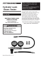
1
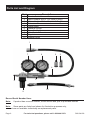
Cylinder LeakDown Tester
Item 94190
INSTRUCTIONS AND
PRECAUTIONS
Visit our website at:
http://www.harborfreight.com
Read this material before
using this product.
Failure to do so can result
in serious injury.
SAVE THIS MANUAL.
Manual Revised 09b; 11c; 11f
When unpacking, make sure
that the product is intact and
undamaged.
If any parts are missing or broken,
please call 1‑800‑444‑3353
as soon as possible.
Copyright© 2006 by Harbor Freight Tools®.
All rights reserved. No portion of this document
or any artwork contained herein may be
reproduced in any shape or form without the
express written consent of Harbor Freight
Tools. Diagrams within this document may
not be drawn proportionally. Due to continuing
improvements, actual product may differ slightly
from the product described herein. Tools required
for assembly and service may not be included.
For technical questions or replacement
parts, please call 1‑800‑444‑3353.
Specifications
Adapters
Included
12mm and 14mm
Spark Plug Adapters
Gauges
2½ IN. dia. rubber protected
Gauge Scale
0 to 100 PSI in 2 PSI
increments; 0 - 7 bar in
0.2 bar increments
Maximum
Air Pressure
100 PSI
Important Safety Information
1. Keep work area clean.
Cluttered areas invite injuries.
2. Observe work area conditions.
Do not use machines or power
tools in damp or wet locations.
Don’t expose to rain. Keep work area
well lighted. Do not use electrically
powered tools in the presence
of flammable gases or liquids.
Be aware of the inherent dangers
of working on a gasoline engine.
3. Keep children away.
Children must never be allowed in the
work area. Do not let them handle
machines, tools, or extension cords.
4. Store idle equipment. When not
in use, tools must be stored in a dry
location to inhibit rust. Always lock up
tools and keep out of reach of children.
5. Use the right tool for the job.
This cylinder tester is intended for
use in gasoline powered engines.
Do not modify this tool and do
not use this tool for a purpose
for which it was not intended.
6. Dress properly. Do not wear loose
clothing or jewelry as they can be
caught in moving parts. Protective,
Page 2
electrically nonconductive clothes and
nonskid footwear are recommended
when working. Wear restrictive hair
covering to contain long hair.
7. Wear ANSI-approved impact
safety goggles when working
on gasoline engines.
8. Be sure to work in a well ventilated
place, or pipe exhaust gasses to the
outdoors. Guard against exposure to
Carbon Monoxide, which is an odorless,
colorless gas produced by gasoline
engines. Carbon Monoxide exposure
may cause serious injury or death.
9. Do not overreach. Keep proper footing
and balance at all times. Do not reach
over or across running machines.
10. Maintain tools with care. Keep tester
threads sharp and clean for better
and safer performance. Follow
instructions for lubricating and changing
accessories. The gauge hose and
adapters must be kept clean, dry, and
free from oil and grease at all times.
11. Stay alert. Watch what you are
doing, use common sense. Do not
operate any tool when you are tired.
12. Check for damaged parts. Before
using any tool, any part that appears
damaged should be carefully checked
to determine that it will operate
properly and perform its intended
function. Any part that is damaged
should be properly repaired or
replaced by a qualified technician.
13. Replacement parts and accessories.
When servicing, use only identical
replacement parts. Use of any
other parts will void the warranty.
14. Do not operate tool if under the
influence of alcohol or drugs.
Read warning labels on prescriptions to
determine if your judgment or reflexes
are impaired while taking drugs. If there
is any doubt, do not operate the tool.
For technical questions, please call 1-800-444-3353.
SKU 94190
15. Maintenance. For your safety, service
and maintenance should be performed
regularly by a qualified technician.
16. People with pacemakers should
consult their physician(s) before use.
Electromagnetic fields in close proximity
to heart pacemaker could cause
pacemaker interference or pacemaker
failure. Caution is necessary when near
coil, spark plug cables, or distributor
of running engine. Engine should be
off during distributor adjustment.
17. WARNING: The brass components of
this product contain lead, a chemical
known to the State of California
to cause birth defects (or other
reproductive harm). (California Health
& Safety code 25249.5, et seq.)
18. The warnings, cautions, and instructions
discussed in this instruction manual
cannot cover all possible conditions
and situations that may occur. It must
be understood by the operator that
common sense and caution are factors
which cannot be built into this product,
but must be supplied by the operator.
SAVE THESE
About Cylinder Leak Testing
A Cylinder Leak-Down Tester can give you
valuable information about the engine’s
compression. Pressurized air is supplied
to each cylinder, and the rate of leakage is
measured in percent loss from 0% to 100%.
The operator may also locate the
source of the compression loss
by listening at these places:
a. Oil dipstick tube for leaking
cylinder rings.
b. Radiator fill cap for
cylinder wall cracks.
c. Adjacent port for head
gasket leaking.
d. Tailpipe for exhaust valve leaks.
e. Carburetor air horn for
intake valve leakage.
f. Fuel injector body for
intake valve leakage.
If you are not experienced in doing this
type of diagnostic test, the work should
be done by a qualified technician.
INSTRUCTIONS.
Important Considerations
About Compression
Loss Testing
1. There will always be some compression
loss past piston rings, even in a new
engine. You will never see a 0%
compression loss, and this lost pressure
should be audible at the oil dipstick port.
2. If the Gauge shows very high or 100%
compression loss, the cylinder may
not be at Top Dead Center (TDC)
on the compression stroke.
Make sure the cylinder is at TDC, so the
SKU 94190
For technical questions, please call 1-800-444-3353.
Page 3
valves are closed. Reference your
vehicle service manual for
instructions on how to do this.
3. A “good” reading will show compression
loss of all cylinders at about the
same rate. A large difference of 15%
to 30% comparing one cylinder to
the others indicates a problem.
4. Leakage rate readings may vary by
up to 10% when taking repeated
readings of the same cylinder. Piston
position and engine temperature can
cause variable readings. Take several
readings and average the results for
a recorded reading for each cylinder.
5. Diagnosing an engine problem with this
tool involves using a listening device
(not included). A length of hose or a
mechanic’s stethoscope are suggested.
6. The lower the sound pitch of
escaping pressure indicates a
larger leak. Small leaks will typically
make a higher pitched sound.
7. If the vehicle has multiple problems,
the Cylinder Leakage Tester may show
only the most pronounced problems.
A large problem may overwhelm a
smaller problem during testing.
Operating Instructions
Read the ENTIRE IMPORTANT
SAFETY INFORMATION
section at the beginning of
this document including all
text under subheadings therein
before set up or use of
this product.
IMPORTANT NOTE: Be sure the Regulator
NOTE: The engine must be at normal
operating temperature for accurate
testing. Start the engine and let it warm
up to normal operating temperature,
then turn it off for testing.
WARNING! Always run an engine in a
well ventilated space. Running engines
produce Carbon Monoxide, a colorless,
odorless gas which can cause serious
personal injury or death if inhaled.
WARNING! Wear protective gloves and
ANSI-approved eye protection when
working on a hot engine. Keep hands
away from the fan and other moving parts,
and protect yourself from electrical shock
or burns. Be aware that working on a
gasoline engine is inherently dangerous,
and suitable precautions must be taken.
1. Before removing the spark plugs,
clean the area around the spark
plugs using compressed air.
It is important to prevent foreign
materials from falling into the cylinders
once the spark plugs are removed.
2. Disconnect the coil wire from the
coil, and remove all spark plugs.
Note the position of the wires so that the
correct wire may be replaced on each
plug at the end of the job. On engines
with two spark plugs per cylinder,
remove only one plug per cylinder.
3. Remove the oil dipstick, radiator cap,
and disconnect one end of the PCV
hose. If the engine has a carburetor,
remove the air cleaner and open
the throttle all the way. If the engine
is fuel injected, remove the air
cleaner or open the throttle body.
4. Position the cylinder to be tested
at TDC on the compression stroke
so all valves are closed.
Knob (9) is turned fully counterclockwise 5. Turn the Regulator Knob fully
counterclockwise. Connect the
before connecting the Cylinder Leakage
Cylinder Leak-Down Tester to a
Tester to a pressurized air source. Failure
to do so may result in damage to the tool.
Page 4
For technical questions, please call 1-800-444-3353.
SKU 94190
compressed air source (not included)
at the male Quick Connector (8).
head gasket, often two or more adjacent
cylinders will show the same problem.
NOTE: Set the air compressor’s regulator
to 7 to 100 PSI. Never operate this
tester with air pressure set higher than
100 PSI, which can damage this tool.
3. Adjacent cylinder indicates a
damaged head gasket.
6. Turn the Regulator Knob (9) clockwise
until the Gauge (6) reads “0” (zero)
at the end of the yellow band.
5. Carburetor or fuel injector
intake indicates stuck, burned
or worn intake valve.
7. Hand screw the Adapter Hose (10)
into the spark plug hole of the cylinder
to be tested. Connect the male end
of the adapter Hose to the female
coupler of the Extension Hose (4).
8. You can now read the amount
of leakage on the Gauge (6)
as a percentage loss.
9. Test the remaining cylinders
to determine which if any
cylinders are bad.
10. Use the diagnostic techniques
in the next section to determine
the cause of the problem.
Diagnostic Techniques
If one or more cylinders are identified as
having 15% to 30% greater compression
loss than the others, you can listen for
escaping air pressure to diagnose the
problem. Air escaping at the following
locations indicates a potential problem.
4. Tail pipe indicates burned,
stuck or worn exhaust valve.
Maintenance and Servicing
1. BEFORE EACH USE, inspect general
condition of tool. Check for loose
hardware, misalignment or cracked or
broken parts, and any other condition
that may affect its safe operation.
2. AFTER USE, wipe external surfaces
of the tool with clean cloth.
3. Periodically check the
threads for damage.
4. Keep clean and free from dirt,
grease and grit.
5. Release the pressure from
the gauge before storing.
6. Store it in its case when not in use.
1. Oil dipstick tube indicates pressure
escaping from the cylinder into the oil
jacket. This usually indicates stuck,
burned or worn rings or cylinder walls.
2. Radiator filler opening bubbles or
sound indicates pressure escaping into
the coolant jacket. This can indicate
cracked cylinder walls or a damaged
head gasket. In case of a damaged
SKU 94190
For technical questions, please call 1-800-444-3353.
Page 5
Parts List and Diagram
Part
1
2
3
4
5
6
7
8
9
10
Description
Female Quick Connector
Metric Adapter M12 x 1.25 (with O-Ring)
Metric Adapter M14 x 1.5 (with O-Ring)
Extension Hose
Gauge Base
Leakage Gauge
Pressure Gauge
Male Quick Connector
Regulator
Adapter Hose
1
7
6
2
3
4
5
8
10
9
Record Serial Number Here:
Note:
If product has no serial number, record month and year of purchase instead.
Note: Some parts are listed and shown for illustration purposes only,
and are not available individually as replacement parts.
Page 6
For technical questions, please call 1-800-444-3353.
SKU 94190
Limited 90 Day Warranty
Harbor Freight Tools Co. makes every effort to assure that its products meet high
quality and durability standards, and warrants to the original purchaser that this
product is free from defects in materials and workmanship for the period of 90 days
from the date of purchase. This warranty does not apply to damage due directly or
indirectly, to misuse, abuse, negligence or accidents, repairs or alterations outside
our facilities, criminal activity, improper installation, normal wear and tear, or to lack of
maintenance. We shall in no event be liable for death, injuries to persons or property,
or for incidental, contingent, special or consequential damages arising from the use
of our product. Some states do not allow the exclusion or limitation of incidental or
consequential damages, so the above limitation of exclusion may not apply to you. THIS
WARRANTY IS EXPRESSLY IN LIEU OF ALL OTHER WARRANTIES, EXPRESS OR
IMPLIED, INCLUDING THE WARRANTIES OF MERCHANTABILITY AND FITNESS.
To take advantage of this warranty, the product or part must be returned to us
with transportation charges prepaid. Proof of purchase date and an explanation
of the complaint must accompany the merchandise. If our inspection verifies
the defect, we will either repair or replace the product at our election or we may
elect to refund the purchase price if we cannot readily and quickly provide you
with a replacement. We will return repaired products at our expense, but if we
determine there is no defect, or that the defect resulted from causes not within the
scope of our warranty, then you must bear the cost of returning the product.
This warranty gives you specific legal rights and you may also
have other rights which vary from state to state.
PLEASE READ THE FOLLOWING CAREFULLY
THE MANUFACTURER AND/OR DISTRIBUTOR HAS PROVIDED THE PARTS LIST AND ASSEMBLY
DIAGRAM IN THIS MANUAL AS A REFERENCE TOOL ONLY. NEITHER THE MANUFACTURER
OR DISTRIBUTOR MAKES ANY REPRESENTATION OR WARRANTY OF ANY KIND TO THE
BUYER THAT HE OR SHE IS QUALIFIED TO MAKE ANY REPAIRS TO THE PRODUCT, OR
THAT HE OR SHE IS QUALIFIED TO REPLACE ANY PARTS OF THE PRODUCT. IN FACT, THE
MANUFACTURER AND/OR DISTRIBUTOR EXPRESSLY STATES THAT ALL REPAIRS AND PARTS
REPLACEMENTS SHOULD BE UNDERTAKEN BY CERTIFIED AND LICENSED TECHNICIANS,
AND NOT BY THE BUYER. THE BUYER ASSUMES ALL RISK AND LIABILITY ARISING OUT OF
HIS OR HER REPAIRS TO THE ORIGINAL PRODUCT OR REPLACEMENT PARTS THERETO,
OR ARISING OUT OF HIS OR HER INSTALLATION OF REPLACEMENT PARTS THERETO.
SKU 94190
For technical questions, please call 1-800-444-3353.
Page 7
3491 Mission Oaks Blvd. • PO Box 6009 • Camarillo, CA 93011 • (800) 444-3353