1
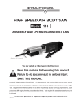
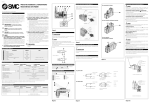
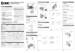
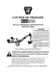
2.5 HP HORIZONTAL OHV
GASOLINE ENGINE
Model 97964
Set up, Operating, and Servicing Instructions
Using an engine indoors CAN KILL YOU IN
MINUTES.
Engine exhaust contains carbon monoxide.
This is a poison you cannot see or smell.
NEVER use inside
a home or garage,
EVEN IF doors and
windows are open.
Only use OUTSIDE
and far away from
windows, doors, and
vents.
Visit our website at: http://www.harborfreight.com
Read this material before using this product.
Failure to do so can result in serious injury.
Save this manual.
Copyright© 2008 by Harbor Freight Tools®. All rights reserved. No portion of this manual or any artwork
contained herein may be reproduced in any shape or form without the express written consent of Harbor
Freight Tools. Diagrams within this manual may not be drawn proportionally. Due to continuing improvements,
actual product may differ slightly from the product described herein.
For technical questions or replacement parts, please call 1-800-444-3353.
Manual Revised 09i
Contents
PARTS LIST��������������������������������� 16
ASSEMBLY DIAGRAM���������������� 17
Important SAFETY
Information���������������������������� 3
Limited 1 year / 90 Day
warranty������������������������������ 18
Basic Specifications������������� 6
Unpacking���������������������������������� 6 Emission Control System
Warranty������������������������������ 18
Set Up Instructions��������������� 6
Operating Instructions������ 7
Engine Controls������������������������� 7
Starting the Engine������������������� 7
Checking and Filling
Engine Oil������������������������������� 7
Checking and Filling Fuel�� 8
Start Procedure������������������� 9
Break-in Period���������������������� 9
Technical Specifications�� 10
Servicing���������������������������������� 10
Maintenance Procedures����� 10
Engine Oil Change��������������� 10
Air Filter Element
Maintenance����������������������� 11
Spark Plug Maintenance�� 11
Inspection, maintenance,
and cleaning schedule��� 12
After Initial 20
Operation Hour Period:� 12
Every 25 Operation
Hours Thereafter:����������� 12
Every 50 Operation
Hours:������������������������������������ 12
Every 100 Operation
Hours:������������������������������������ 12
Every 300 Operation
Hours:������������������������������������ 12
Storage����������������������������������������12
Troubleshooting���������������������� 14
SKU 97964
For technical questions, please call 1-800-444-3353.
Page 2
Save This Manual
NOTICE is used to
address practices
not related to personal injury.
Keep this manual for the safety warnings and precautions, assembly, operating, inspection, maintenance and cleaning
procedures. Write the product’s serial
number in the back of the manual near the
assembly diagram (or month and year of
purchase if product has no number). Keep
this manual and the receipt in a safe and
dry place for future reference.
CAUTION, without
the safety alert
symbol, is used to address
practices not related to
personal injury.
WARNING! Read all instructions.
Failure to follow all instructions
listed below may result in fire,
serious injury and/or DEATH.
The warnings and precautions
discussed in this manual cannot
cover all possible conditions and
situations that may occur. It must
be understood by the operator that
common sense and caution are
factors which cannot be built into
this product, but must be supplied
by the operator.
Important SAFETY
Information
In this manual, on the labeling,
and all other information
provided with this product:
This is the safety alert
symbol. It is used to alert
you to potential personal
injury hazards. Obey all
safety messages that
follow this symbol to avoid
possible injury or death.
DANGER indicates
a hazardous
situation which, if not
avoided, will result in death or
serious injury.
WARNING
indicates a
hazardous situation which, if
not avoided, could result in
death or serious injury.
CAUTION, used
with the safety
alert symbol, indicates a
hazardous situation which, if
not avoided, could result in
minor or moderate injury.
SKU 97964
SAVE THESE INSTRUCTIONS
Set up precautions
1.
Gasoline fuel and fumes are flammable, and potentially explosive. Use
proper fuel storage and handling procedures. Do not store fuel or other
flammable materials nearby.
2.
Have multiple ABC class fire extinguishers nearby.
3.
Operation of this Engine may create
sparks that can start fires around dry
vegetation.
A spark arrestor may be required.
The operator should contact local fire
agencies for laws or regulations relating to fire prevention requirements.
For technical questions, please call 1-800-444-3353.
Page 3
4.
Mount and use the Engine securely
and only on a flat, level, well-ventilated surface.
5.
Wear ANSI-approved safety goggles,
heavy-duty work gloves, and dust
mask/respirator during set up.
6.
Use only oil and fuel recommended
in the “Specifications” section of this
manual.
Operating precautions
1.
Carbon Monoxide
Hazard
Using an engine indoors
CAN KILL YOU IN
MINUTES.
Engine exhaust contains carbon
monoxide. This is a poison you
cannot see or smell.
NEVER use inside a home or garage,
EVEN IF doors and windows are
open.
Only use OUTSIDE and far away
from windows, doors, and vents.
2.
Keep children away from the Engine,
especially while it is operating.
3.
Do not leave the Engine unattended
when it is running. Turn off the Engine before leaving the work area.
SKU 97964
4.
Wear ANSI-approved safety goggles
and hearing protection during use.
5.
People with pacemakers should
consult their physician(s) before
use. Electromagnetic fields in close
proximity to a heart pacemaker could
cause pacemaker interference or
pacemaker failure. Caution is necessary when near the engine’s magneto
or recoil starter.
6.
Use only accessories that are recommended by Harbor Freight Tools for
your model. Accessories that may be
suitable for one Engine may become
hazardous when used on another
piece of Engine.
7.
Do not operate in explosive atmospheres, such as in the presence of
flammable liquids, gases, or dust.
Gasoline-powered engines may ignite
the dust or fumes.
8.
Stay alert, watch what you are doing
and use common sense when operating this Engine. Do not use this Engine while tired or under the influence
of drugs, alcohol or medication.
9.
Do not overreach. Keep proper footing and balance at all times. This
enables better control of the Engine
in unexpected situations.
10. Dress properly. Do not wear loose
clothing or jewelry. Keep hair, clothing and gloves away from moving
parts. Loose clothes, jewelry or long
hair can be caught in moving parts.
11. Parts, especially exhaust system
components, get very hot during use.
Stay clear of hot parts.
12. Do not cover the Engine during operation.
For technical questions, please call 1-800-444-3353.
Page 4
13. Keep the Engine and surrounding
area clean at all times.
14. Use the Engine in accordance with
these instructions and in the manner intended for the particular type
of Engine, taking into account the
working conditions and the work to be
performed. Use of the Engine for operations different from those intended
could result in a hazardous situation.
15. Do not operate the Engine with
known leaks in the Engine’s fuel
system.
16. This product contains or, when used,
produces a chemical known to the
State of California to cause cancer
and birth defects or other reproductive harm. (California Health & Safety
Code § 25249.5, et seq.)
17. When spills of fuel or oil occur, they
must be cleaned up immediately.
Dispose of fluids and cleaning materials as per any local, state, or federal
codes and regulations. Store oil rags
in a bottom-ventilated, covered, metal
container.
Service precautions
1.
a.Turn the Power Switch (94) to its
“OFF” position.
b.Allow the Engine to completely
cool.
c.Then, remove the Spark Plug Wire
from the Spark Plug.
2.
Keep all safety guards in place and in
proper working order. Safety guards
include Muffler, Air Cleaner, mechanical guards, and heat shields, among
other guards.
3.
Do not alter or adjust any part of
the Engine that is sealed by the
manufacturer or distributor. Only
a qualified service technician may
adjust parts that may increase or
decrease governed Engine speed.
4.
Wear ANSI-approved safety goggles,
heavy-duty work gloves, and dust
mask/respirator during service.
5.
Maintain labels and nameplates on
the Engine. These carry important
information. If unreadable or missing, contact Harbor Freight Tools for a
replacement.
6.
Have the Engine serviced by a qualified repair person using only identical replacement parts. This will
ensure that the safety of the Engine
is maintained. Do not attempt any
service or maintenance procedures
not explained in this manual or any
procedures that you are uncertain
about your ability to perform safely or
correctly.
18. Keep hands and feet away from
moving parts. Do not reach over or
across the Engine while operating.
19. Before use, check for misalignment
or binding of moving parts, breakage
of parts, and any other condition that
may affect the Engine’s operation.
If damaged, have the Engine serviced before using. Many accidents
are caused by poorly maintained
engines.
20. Use the correct Engine for the application. Do not modify the Engine and
do not use the Engine for a purpose
for which it is not intended.
SKU 97964
Before service, maintenance, or
cleaning:
For technical questions, please call 1-800-444-3353.
Page 5
7.
Store the Engine out of the reach of
children.
information, refer to the last pages of this
manual.
8.
Follow scheduled engine maintenance.
At high altitudes, the Engine’s carburetor, governor and any other parts that
control the fuel-air ratio will need to be
adjusted by a qualified mechanic to allow
efficient high-altitude use and to prevent
damage to the Engine and any other devices used with this product.
Refueling Precautions:
1.
Do not smoke, or allow sparks,
flames, or other sources of ignition
around the Engine, especially when
refuelling.
2.
Do not refill the fuel tank while the
Engine is running or hot.
3.
Do not fill fuel tank to the top. Leave
a little room for the fuel to expand as
needed.
4.
Refuel in a well-ventilated area only.
Save these
instructions.
Basic Specifications
Fuel
Engine Oil
Type
89+ octane unleaded
gasoline
Capacity
.42 Gal. (1.4 liters)
Type
SAE 30W
(above 32° F)
SAE 5W-30
(at 32° F or below)
Capacity
13.5 Oz. (0.4 liters)
Note: Additional specifications found in
the Technical Engine Specifications chart in this manual.
The emission control system for this
engine is warranted for standards set by
the U.S. Environmental Protection Agency
and by the California Air Resources Board
(also known as CARB). For warranty
Unpacking
When unpacking, check to make sure
that the item is intact and undamaged. If
any parts are missing or broken, please
call Harbor Freight Tools at the number
shown on the cover of this manual as soon
as possible.
Set Up Instructions
Read the entire Important
Safety Information
section at the beginning of this
manual including all text under
subheadings therein before set
up or use of this product.
To prevent
serious injury
from accidental
starting:
Turn the Power Switch of the
equipment to its “OFF”
position, wait for the engine to
cool, and disconnect the
spark plug wire(s) before
assembling or making any
adjustments to the equipment.
To prevent
serious injury:
Operate only with proper
spark arrestor installed.
REV 08e
SKU 97964
For technical questions, please call 1-800-444-3353.
Page 6
Operation of this equipment
may create sparks that
can start fires around dry
vegetation.
A spark arrestor may be
required.
The operator should contact
local fire agencies for laws
or regulations relating to fire
prevention requirements.
Note: For additional information regarding
the parts listed in the following pages,
refer to the Assembly Diagram near
the end of this manual.
Note: See Mounting Base Layout Diagram
and Engine Shaft Layout Diagram on
page 10.
1.
2.
3.
The tapered Crankshaft (55) is 5/8”
at its thickest diameter. Therefore,
the Belt Pulley or Sprocket Pulley
(neither included) attached to the
Crankshaft must have a 5/8” inside
diameter. The Belt/Sprocket Pulley and Belt/Chain used must have
proper guards (not included) attached
for safety purposes.
Make sure to mount the Engine on a
sturdy equipment surface capable of
supporting the weight of the Engine
and the equipment itself.
The equipment to which the Engine
will be attached must have matching
bolt hole patterns and be attached
using the proper size bolts (not included).
subheadings therein before set
up or use of this product.
Engine Controls
CHOKE
(22)
FUEL VALVE
(93)
FIGURE A
THROTTLE
(64)
POWER
SWITCH
(94)
STARTER HANDLE
(83)
Starting the Engine
Inspect Engine and equipment
looking for damaged, loose,
and missing parts before set up
and starting. If any problems
are found, do not use until
properly repaired.
Checking and Filling Engine Oil
CAUTION! Your Warranty is VOID if the
Engine’s crankcase is not properly
filled with oil before each use. Before
each use, check the oil level. Do not
run the Engine with low or no engine
oil. Running the Engine with no or
low engine oil WILL permanently
damage the Engine.
Operating Instructions
Read the entire Important
Safety Information
section at the beginning of this
manual including all text under
SKU 97964
For technical questions, please call 1-800-444-3353.
REV 08h
Page 7
FIGURE B
4.
Replace the Oil Dipstick.
(See Figure B.)
CAUTION! Do not run the Engine with too
little or too much oil. The Engine will
be permanently damaged.
Checking and Filling Fuel
WARNING! To prevent
serious injury from
fire:
Fill the Fuel Tank in a well-ventilated area away from ignition sources. Do not smoke.
FIGURE D
FUEL TANK
(96)
DIPSTICK
(48)
1.
FUEL TANK FILTER
(96)
Remove the Dipstick and wipe it off
with a clean rag. (See Figure B.)
FIGURE C
FUEL TANK CAP
(96)
1.
To fill the Fuel Tank (96), first wipe off
the Fuel Tank Cap (96) and the surrounding area. (See Figure D.)
2.
Unscrew, and remove the Fuel Tank
Cap (96). (See Figure D.)
3.
Mix fuel stabilizer (not included) with
89 octane (or better) unleaded gasoline according to fuel stabilizer directions.
4.
Fill the Fuel Tank (96) to about 1 inch
under the fill neck of the Fuel Tank
with the stabilized unleaded gasoline
mixture. (See Figure D.)
5.
Then replace the Fuel Tank Cap (96).
(See Figure D.)
DIPSTICK
(48)
2.
3.
Reinsert the Dipstick completely and
remove it to check the oil level. The
oil level should be between the high
and low marks on the Dipstick.
(See Figure C.)
If the oil level is below the low mark
add the appropriate type of oil until
the oil level is between the high and
the low marks.
Oil type:
32° F or above = SAE 30W
Below 32° F = SAE 5W-30
SKU 97964
For technical questions, please call 1-800-444-3353.
Page 8
6.
NOTE: Always check the Fuel Tank
Filter (96) for excess dirt and debris
before each use. If necessary, remove and clean the Fuel Tank Filter.
Then re-install the Filter in the Fuel
Tank (96) and replace the Fuel Tank
Cap (96). (See Figure D.)
its “RUN” position. Then adjust the
Throttle (64) to the desired Engine
speed (RPM). (See Figure E.)
6.
IMPORTANT: Allow the Engine to run
at no load until warm (1-5 minutes)
with no load after each start-up to allow the Engine to stabilize.
Start Procedure
FIGURE E
Before starting the Engine:
a.Follow the Set Up Instructions to prepare the Engine.
b.Inspect the Engine.
c.Fill the Engine with the proper amount and type of fuel
and oil.
Note: This engine includes an automatic
low oil shutdown sensor that disables
the engine if the oil level is too low.
d.Read the Equipment Operation section that follows.
1.
Turn the Engine Fuel Valve (93) to its
“OPEN” position. (See Figure E.)
2.
Turn the Engine Power Switch (94) to
its ON position. (See Figure E.)
3.
Then, turn the Engine Choke Lever
(22) to its “CHOKE” position. Set the
Choke Lever in the “RUN” position
when starting a warm Engine.
(See Figure E.)
4.
5.
Grasp the Starter Handle (83), and
pull slowly until resistance is felt.
While holding the Handle, allow the
Starter Rope to rewind slowly. Then,
pull the Starter Handle with a rapid,
full arm stroke. Repeat as necessary,
until the Engine starts.
(See Figure E.)
After the Engine starts and warms
up, slowly move the Choke Lever to
CHOKE
(22)
FUEL VALVE
(93)
THROTTLE
(64)
POWER
SWITCH
(94)
STARTER HANDLE
(83)
Break-in Period
1.
Breaking-in the Engine will help to
ensure proper equipment and Engine
operation, and will extend the Engine’s lifespan. The warranty is void
if the Engine is not broken in properly.
The first 20 hours of operation is the
break-in period.
2.
During the first 3 hours of use:
• Do not apply a heavy load to the
Engine.
• Do not operate the Engine at its
maximum speed.
3.
Change the engine oil after the first
20 hours of use.
4.
Under normal operating conditions
subsequent maintenance follows the
schedule explained in the “Maintenance and Servicing” section.
REV 09i
SKU 97964
For technical questions, please call 1-800-444-3353.
Page 9
2-9/16” (65mm) Hole Distance
2-31/64”
(63mm) Hole
Distance
4-3/32” (104mm) Hole Distance
REV 08e, 08h
SKU 97964
For technical questions, please call 1-800-444-3353.
Page 10
Technical
Specifications
Engine Type
2.5 HP OHV Single Cylinder
Bore x Stroke
52mm x 38mm
Displacement
79cc
Maximum Engine RPM
3600
Engine Model
152F
Engine Family
8YAMS.0791ST
Engine Shaft Direction
Horizontal
Rotation viewed from PTO
(power takeoff - the output
shaft)
Counterclockwise Facing the
Shaft
Shaft Size/Type
5/8” diameter Keyed
Fuel
Engine Oil
Spark Plug
Type
89+ octane unleaded gasoline
Capacity
.42 Gal. (1.4 liters)
Type
SAE 30W (above 32° F)
SAE 5W-30 (at 32° F or below)
Capacity
13.5 Oz. (0.4 liters)
Type
E6TC or Denso - W20FP-U
Gap
0.027” to 0.031”
Servicing
To prevent
serious injury
from accidental
starting:
Turn the Power Switch (94) of
the Engine to its “OFF”
position, wait for the Engine
to cool, and disconnect the
Spark Plug Wire before
performing any inspection,
maintenance, or cleaning
procedures.
To prevent
serious injury
from equipment failure:
Do not use a damaged
Engine. If abnormal noise,
vibration, or excess smoking
occurs, have the problem
corrected before further use.
Maintenance Procedures
Many maintenance procedures,
including those not detailed
in this manual, will need to
be performed by a qualified
technician for safety. If you
have any doubts about your
ability to safely service the
Engine have a qualified
technician service the Engine
instead.
Note: Warranty is void if proper maintenance and servicing procedures are
not followed.
Engine Oil Change
CAUTION! Oil is very hot during operation and can cause burns. Wait for
Engine to cool before changing oil.
1.
Place a drain pan (not included) underneath the Crankcase’s Drain Plug
Bolt (68). (See Figure F.)
FIGURE F
SKU 97964
DRAIN PLUG BOLT (68)
DRAIN PLUG WASHER (69)
2.
Remove the Drain Plug Bolt (68) and,
if possible, tilt the Crankcase slightly
to help drain the oil out. Recycle
used oil. (See Figure F.)
For technical questions, please call 1-800-444-3353.
Page 11
3.
Replace the Drain Plug Bolt and
Drain Plug Washer (69). Replace
the washer, if damaged. Tighten the
plug. (See Figure F.)
5.
4.
Refill the oil to the proper level following the instructions under the “Starting the Engine” section.
Spark Plug Maintenance
1.
Disconnect Spark Plug Wire from end
of the Spark Plug. Clean out debris
from around Spark Plug.
2.
Using the provided Spark Plug
Wrench, remove the Spark Plug.
3.
Inspect the Spark Plug:
If the electrode is oily, clean it using a
clean, dry rag.
If the electrode has deposits on it,
polish it using emery paper.
If the white insulator is cracked or
chipped, the Spark Plug needs to be
replaced.
Air Filter Element Maintenance
FIGURE G
AIR FILTER
HOUSING
(24)
BOLT
(29)
AIR
FILTER
COVER
(28)
1.
BOLT
(29)
APRON
PLATE
(26)
FOAM
AIR FILTER
(27)
FIGURE H
Wipe off the Air Filter Cover (28).
(See Figure G.)
2.
The Air Filter Cover (28) is held in
place by two Bolts (29). Unscrew
and remove the two Bolts.
3.
Remove the Foam Air Filter (27).
Then remove the Apron Plate (26).
(See Figure G.)
4.
Wash the Foam Air Filter (27) and
Apron Plate (26) in warm water and
mild detergent several times. Rinse.
Squeeze out excess water from the
Filter and allow it to dry completely.
Soak the Filter in lightweight oil
briefly, then squeeze out the excess
oil. (See Figure G.)
SKU 97964
Install the cleaned Apron Plate (26)
and Foam Air Filter (27). Secure the
Air Filter Cover (28) with the two Bolts
(29) before use. (See Figure G.)
.027” TO .031”
4.
When installing a new Spark Plug,
adjust the plug’s gap to the specification on the “Technical Specification”
chart. Do not pry against the electrode or the insulator, the Spark Plug
can be damaged. (See Figure H.)
5.
Install the new Spark Plug or the
cleaned Spark Plug into the Engine.
Gasket-style: Finger-tighten until the
gasket contacts the cylinder head,
then tighten about 1/2-2/3 turn more.
Non-gasket-style: Finger-tighten until
the Plug contacts the head, then
about 1/16 turn more.
For technical questions, please call 1-800-444-3353.
Page 12
Inspection, maintenance,
and cleaning schedule
Note: This maintenance schedule is intended solely as a general guide. If
performance decreases or if Engine
operates unusually, check systems
immediately. The maintenance
needs of each part of the Engine will
differ depending on factors such as
duty cycle, temperature, air quality,
fuel quality, and other factors.
Storage
1.
Wait for Engine to cool, then wipe
Engine with clean cloth.
2.
When the Engine is to remain idle
for longer than 20 days, prepare the
Engine for storage as follows:
a.Change engine oil and empty Fuel
Tank (96).
b.Either leave Fuel Tank (96) empty or
refill Fuel Tank with fresh unleaded
gasoline mixed with a fuel stabilizer
intended for long term Engine storage (not included). After filling, run
Engine for about 1 to 2 minutes
to circulate the treated gasoline
through the Carburetor (22). Wait
for Engine to cool before proceeding.
Note: These procedures are in addition to
the regular checks and maintenance
explained as part of the regular operation of the Engine and equipment.
After Initial 20 Operation Hour Period:
a.Change engine oil.
c. Clean out area around Spark Plug.
Remove Spark Plug and pour one
tablespoon of engine oil into cylinder
through Spark Plug hole.
Every 25 Operation Hours Thereafter:
a.Clean/replace Foam Air Filter (27).
b.Inspect/clean Spark Plug.
d.Reinstall Spark Plug, but leave
Spark Plug Wire disconnected.
Every 50 Operation Hours:
a.Change engine oil.
e.Pull Recoil Starter once to distribute
oil in cylinder. Stop after one or two
revolutions when you feel the piston
start the compression stroke (when
you start to feel resistance).
Every 100 Operation Hours:
a.Replace Spark Plug.
b.Replace Foam Air Filter.
Note: All maintenance procedures scheduled for 25, 50, and 100 operation
hours should be performed at least
yearly.
Every 300 Operation Hours:
a.Clean Fuel Tank (96) and Carburetor
(22).
b.Clean carbon build-up from combustion chamber.
SKU 97964
3.
Apply a thin coat of rust preventive oil
to all uncoated metal parts.
4.
Cover and store in a dry, well-ventilated area out of reach of children.
5.
Before starting the Engine after storage, keep in mind that untreated
gasoline will deteriorate quickly.
Drain the Fuel Tank and change to
fresh fuel if untreated gasoline has
been sitting for a month, if treated
gasoline has been sitting beyond the
For technical questions, please call 1-800-444-3353.
Page 13
fuel stabilizer’s recommended time
period, or if the Engine does not start
properly.
PLEASE READ THE
FOLLOWING CAREFULLY
The manufacturer and/or
distributor has provided the
parts list and assembly diagram
in this manual as a reference
tool only. Neither the
manufacturer or distributor
makes any representation
or warranty of any kind to
the buyer that he or she is
qualified to make any repairs
to the product, or that he or
she is qualified to replace
any parts of the product. In
fact, the manufacturer and/
or distributor expressly
states that all repairs and
parts replacements should
be undertaken by certified
and licensed technicians, and
not by the buyer. The buyer
assumes all risk and liability
arising out of his or her repairs
to the original product or
replacement parts thereto,
or arising out of his or her
installation of replacement
parts thereto.
SKU 97964
For technical questions, please call 1-800-444-3353.
Page 14
Problem
Engine will not
start
Troubleshooting
Possible Cause
Possible Solution
Fuel Related:
1. No fuel in tank or fuel valve closed.
2. Choke not in start position,
especially with cold engine.
3. Low quality or deteriorated, old
gasoline.
4. Carburetor not primed.
Fuel Related:
1. Fill fuel tank and open fuel valve.
2. Move choke to start position if engine
is cold.
3. Use only fresh 89+ octane unleaded
gasoline.
4. Prime carburetor by pressing priming
bulb specified number of times
(if equipped). Replace broken or
damaged bulb.
5. Clean out passageways using fuel
additive. Heavy deposits may require
further cleaning.
6. Gently tap side of carburetor float
chamber with screwdriver handle.
7. Turn choke to run position. Remove
spark plug and pull the start handle
several times to air out the chamber.
Reinstall spark plug and set choke to
start position.
5. Dirty fuel passageways blocking
fuel flow.
6. Carburetor needle stuck. Fuel
can be smelled in the air.
7. Too much fuel in chamber. This
can be caused by the carburetor
needle sticking.
Ignition (spark) Related:
1. Spark plug wire not connected
securely.
2. Spark plug electrode wet or dirty.
3. Incorrect spark plug gap.
4. Spark plug wire or spark plug
broken.
5. Incorrect spark timing or faulty
ignition system.
Ignition (spark) Related:
1. Connect spark plug wire properly.
Compression Related:
1. Cylinder not lubricated. This can
be a problem after long storage
periods.
2. Loose or broken spark plug.
(Hissing noise will occur when
trying to start.)
Compression Related:
1. Pour tablespoon of oil into spark plug
hole. Crank engine a few times and
try to start again.
2. Tighten spark plug. If that does not
work, replace spark plug. If problem
persists, may have head gasket
problem, see #3.
3. Tighten head. If that does not
remedy problem, replace head
gasket.
4. Adjust valve clearance. If that does
not work, clean or replace valves/
tappets.
3. Loose cylinder head or damaged
head gasket. (Hissing noise will
occur when trying to start.)
4. Engine valves or tappets
misadjusted or stuck.
2. Clean spark plug.
3. Correct spark plug gap.
4. Replace spark plug wire and/or spark
plug.
5. Have qualified technician diagnose/
repair ignition system.
Follow all safety precautions whenever diagnosing or servicing the
equipment or engine.
SKU 97964
For technical questions, please call 1-800-444-3353.
Page 15
Problem
Engine misfires
Troubleshooting
Possible Cause
1. Spark plug wire loose.
2. Incorrect spark plug gap or
damaged spark plug.
3. Defective spark plug wire.
4. Old or low quality gasoline.
5. Incorrect compression.
Engine stops
suddenly
1. Low oil shutdown.
Engine knocks
1. Old or low quality gasoline.
Possible Solution
1. Check wire connections.
2. Re-gap or replace spark plug.
3. Replace spark plug wire.
4. Use only fresh 89+ octane unleaded
gasoline.
5. Diagnose and repair compression.
(Use Engine will not start:
Compression Related section.)
1. Fill engine oil to proper level. Check
engine oil before EVERY use.
2. Fuel tank empty or full of impure
2. Fill fuel tank with fresh 89+ octane
or low quality gasoline.
unleaded gasoline.
3. Defective fuel tank cap creating 3. Test/replace fuel tank cap.
vacuum, preventing proper fuel flow.
4. Improper idle speed.
4. Properly adjust idle speed.
5. Faulty magneto, incorrect timing, 5. Have qualified technician diagnose
or clogged carburetor.
and service engine.
2. Engine overloaded.
3. Incorrect spark timing, deposit
buildup, worn engine, or other
mechanical problems.
Engine backfires 1. Impure or low quality gasoline.
2. Engine too cold.
3. Choke not open after engine
warm.
4. Engine not properly adjusted for
high altitude operation.
5. Intake valve stuck, choke
stuck, incorrect timing, clogged
carburetor, or overheated engine.
1. Fill fuel tank with fresh 89+ octane
unleaded gasoline.
2. Do not exceed equipment’s load
rating.
3. Have qualified technician diagnose
and service engine.
1. Fill fuel tank with fresh 89+ octane
unleaded gasoline.
2. Use cold weather fuel and oil
additives to prevent backfiring.
3. Move choke to run position after
engine warms up.
4. Qualified technician must adjust
engine at altitudes greater than 5,000
feet above sea level.
5. Have qualified technician diagnose
and service engine.
Follow all safety precautions whenever diagnosing or servicing the
equipment or engine.
Record Product’s Serial Number Here:
Note: If product has no serial number, record month and year of purchase instead.
Note: Some parts are listed and shown for illustration purposes only, and are not available individually as replacement parts.
SKU 97964
For technical questions, please call 1-800-444-3353.
Page 16
PARTS LIST
CASE COVER
THROTTLE
CARBURETOR W/CHOKE
CARBURETOR SPACER
BOLT
MUFFLER
FAN COVER
EXHAUST VALVE
INTAKE VALVE
POWER SWITCH
DIPSTICK
SKU 97964
For technical questions, please call 1-800-444-3353.
Page 17
ASSEMBLY DIAGRAM
SKU 97964
For technical questions, please call 1-800-444-3353.
Page 18
Limited 1 year / 90 Day
warranty
Harbor Freight Tools Co. makes every effort to assure that its products meet
high quality and durability standards, and
warrants to the original purchaser that
for a period of ninety days from date of
purchase that the engine/motor, the belts
(if so equipped), and the blades (if so
equipped) are free of defects in materials
and workmanship. Harbor Freight Tools
also warrants to the original purchaser,
for a period of one year from date of purchase, that all other parts and components
of the product are free from defects in materials and workmanship (90 days if used
by a professional contractor or if used as
rental equipment). This warranty does not
apply to damage due directly or indirectly,
to misuse, abuse, negligence or accidents,
repairs or alterations outside our facilities,
normal wear and tear, or to lack of maintenance. We shall in no event be liable for
death, injuries to persons or property, or
for incidental, contingent, special or consequential damages arising from the use
of our product. Some states do not allow
the exclusion or limitation of incidental or
consequential damages, so the above
limitation of exclusion may not apply to
you. This warranty is expressly
in lieu of all other warranties,
express or implied, including
the warranties of merchantability and fitness.
To take advantage of this warranty,
the product or part must be returned to us
with transportation charges prepaid. Proof
of purchase date and an explanation of the
complaint must accompany the merchandise. If our inspection verifies the defect,
we will either repair or replace the product
at our election or we may elect to refund
SKU 97964
the purchase price if we cannot readily
and quickly provide you with a replacement. We will return repaired products at
our expense, but if we determine there is
no defect, or that the defect resulted from
causes not within the scope of our warranty, then you must bear the cost of returning
the product.
This warranty gives you specific legal
rights and you may also have other rights
which vary from state to state.
3491 Mission Oaks Blvd. • PO Box
6009 • Camarillo, CA 93011 • (800)
444-3353
Emission Control
System Warranty
California and United States Emission Control
Defects Warranty Statement
The California Air Resources Board (herein CARB), the United
States Environmental Protection Agency (herein EPA), and Harbor
Freight Tools (herein HFT) are pleased to explain the emission control system warranty on your 1995 and later Small Off-Road Engine
(herein engine). In California, the engine must be designed, built
and equipped to meet the State’s stringent anti-smog standards.
Elsewhere within the United States, new off-road, spark-ignition
engines certified for model year 1997 and later, must meet similar
standards set forth by the EPA. HFT must warrant the emission
control system on your engine for the periods of time described
below, provided there has been no abuse, neglect or improper
maintenance of your engine.
Your emission control system may include parts such as the
carburetor or fuel-injection system, and the ignition system. Also
included may be hoses, belts, connectors and other emissionrelated assemblies.
Where a warrantable condition exists, HFT will repair your
engine at no cost to you including diagnosis, parts and labor.
Manufacturer’s Warranty Coverage
The 1995 and later engines are warranted for two (2) years.
If any emission-related part on your engine is defective, the part
will be repaired or replaced by HFT.
Harbor Freight Tools Emission Control Defects
Warranty Coverage
Engines are warranted for a period of two (2) years relative to
emission control parts defects, subject to the provisions set forth
below. If any emission related part on your engine is defective, the
part will be repaired or replaced by HFT.
For technical questions, please call 1-800-444-3353.
Page 19
Owner’s Warranty Responsibilities
• As the engine owner, you are responsible for the performance
of the required maintenance listed in your Owner’s Manual.
HFT recommends that you retain all receipts covering maintenance on your engine, but HFT cannot deny warranty
solely for the lack of receipts or for your failure to ensure the
performance of all scheduled maintenance.
• As the engine owner, you should, however, be aware that
HFT may deny you warranty coverage if your engine or a part
has failed due to abuse, neglect, improper maintenance, or
unapproved modifications.
• You are responsible for shipping your engine to a HFT warranty station as soon as a problem exists. Contact the HFT
Customer Service department at the number below to make
shipping arrangements. The warranty repairs should be
completed in a reasonable amount of time, not to exceed
30 days.
If you have any questions regarding your warranty rights
and responsibilities, you should contact the Harbor Freight Tools
Customer Service Department at 1-800-444-3353.
Harbor Freight Tools Emission Control Defects
Warranty Provisions
1. Length of Coverage
HFT warrants to a first retail purchaser and each subsequent
purchaser that the engine is free from defects in materials
and workmanship that cause the failure of warranted parts
for a period of two (2) years after the date of delivery to the
first retail purchaser.
5. Service and Maintenance
Component parts which are not scheduled for replacement
as required maintenance or are scheduled only for regular
inspection to the effect of “repair or replace as necessary”
are warranted for the warranty period. Any warranted part
which is scheduled for replacement as required maintenance
is warranted for the period of time up to the first scheduled
replacement point for that part. Any replacement part, provided it is equivalent in durability and performance, may be
used in performance of maintenance or repairs. The owner
is responsible for commissioning a qualified technician/mechanic to perform all required maintenance, as outlined in
the Inspection, Cleaning, and Maintenance section in this
manual.
6. Warranted Parts
1.
2.
3.
4.
2. No Charge Repair or Replacement
Repair or replacement of any warranted part will be performed
at no charge to the owner if the work is performed through a
warranty station authorized by HFT. For emissions warranty
service, contact the HFT Customer Service Department at
1-800-444-3353.
5.
Fuel Metering System
i. Carburetor and its internal parts.
ii. Fuel pump (if so equipped).
iii. Cold start enrichment system.
Air Induction System
i. Intake pipe/manifold.
ii. Air cleaner.
Ignition System
i. Spark plug.
ii. Magneto ignition system.
Catalyst System (if so equipped)
i. Exhaust pipe stud.
ii. Muffler.
iii. Catalytic converter (if so equipped).
Miscellaneous Items Used in Above Systems
i. Vacuum, temperature and time sensitive valves
and switches.
ii. Hoses, belts, connectors, and assemblies.
3. Consequential Damages Coverage
Coverage under this warranty shall also extend to the failure
of any engine components caused by the failure of any warranted part while it is still covered under this warranty.
4. Coverage Exclusions
Warranty claims shall be filed in accordance with the provisions of the HFT warranty policy explained in the box at the
top of the previous page. HFT shall not be liable for any loss
of use of the engine, for any alternative usage, for any damage
to goods, loss of time, or inconvenience. Warranty coverage
shall also be excluded for any part which fails, malfunctions,
or is damaged due to failure to follow the maintenance and
operating instructions set forth in the Owner’s Manual including, but not limited to:
a. Use of parts which are not authorized by HFT
b. Improper installation, adjustment or repair of the engine
or of any warranted part unless performed by an authorized warranty center
c. Failure to follow recommendations on fuel use contained
in the Owner’s Manual
d. Improper or inadequate maintenance of any warranted
parts
e. Repairs performed outside of the authorized warranty
service dealers
f. Alterations by changing, adding to or removing parts
from the engine.
SKU 97964
For technical questions, please call 1-800-444-3353.
Page 20