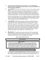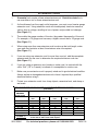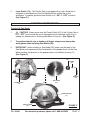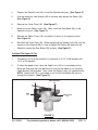
1
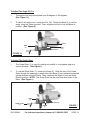
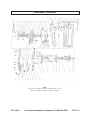
7-1/4” CIRCULAR SAW
WITH LASER
Model 95004
ASSEMBLY AND OPERATING INSTRUCTIONS
Due to continuing improvements, actual product may differ slightly from the product described herein.
®
3491 Mission Oaks Blvd., Camarillo, CA 93011
Visit our Web site at: http://www.harborfreight.com
TO PREVENT SERIOUS INJURY,
READ AND UNDERSTAND ALL WARNINGS
AND INSTRUCTIONS BEFORE USE.
©
Copyright 2006 by Harbor Freight Tools®. All rights reserved. No portion of this
manual or any artwork contained herein may be reproduced in any shape or form
without the express written consent of Harbor Freight Tools.
For technical questions, please call 1-800-444-3353.
PRODUCT SPECIFICATIONS
Item
Electrical Requirements
Laser Specifications
Saw Blade Requirements
Maximum Cutting Depth
Spindle Diameter
Base Plate Dimensions
Fence Guide Dimensions
Additional Features
Overall Dimensions
Net Weight
Description
120 V / 60 Hz / 10 Amps / 5,000 RPM
Power Switch Type: Trigger Switch with Safety Thumb Lock
Power Cord Type: 18AWG x 2 C, SJT / 83-1/2” Long
Power Plug Type: 2-Prong, Polarized
Output Power: 1MW / Wavelength: 650NM
Laser Class I / Required Battery Type: “AAA” (Qty. 2 Included)
7-1/4” Diameter (Included) / Minimum 5,000 RPM Rating
2-1/2” @ 90° / 1-3/4” @ 45°
5/8”
10-5/8” L x 5-5/16” W x 3/8” H
6-1/8” L x 10-3/16” W x 1-1/16” H
Sealed Radial Armature Bearing / Push Button Spindle Lock
Easy Access Carbon Brushes
11-1/8” L x 9-5/8” W x 9” H
8.90 Pounds
CAUTION
LASER LIGHT
DO NOT STARE
INTO BEAM
Max. Output: <1 mW,
Wavelength: 650 nm
CLASS II LASER PRODUCT
This product complies
with 21 CFR 1040.10
and 1040.11
CEN-TECH
3491 Mission Oaks Blvd.,
Camarillo, CA, USA, 93011
Manufacture Date:
, ___________
SAVE THIS MANUAL
You will need this manual for the safety warnings and precautions, assembly,
operating, inspection, maintenance and cleaning procedures, parts list and assembly diagram. Keep your invoice with this manual. Write the invoice number
on the inside of the front cover. Keep this manual and invoice in a safe and dry
place for future reference.
GENERAL SAFETY RULES
WARNING!
READ AND UNDERSTAND ALL INSTRUCTIONS
Failure to follow all instructions listed below may result in
electric shock, fire, and/or serious injury.
SAVE THESE INSTRUCTIONS
WORK AREA
1.
Keep your work area clean and well lit. Cluttered benches and dark areas
invite accidents.
2.
Do not operate power tools in explosive atmospheres, such as in the
presence of flammable liquids, gases, or dust. Power tools create sparks
which may ignite the dust or fumes.
3.
Keep bystanders, children, and visitors away while operating a power tool.
Distractions can cause you to lose control. Protect others in the work area from
SKU 95004
For technical questions, please call 1-800-444-3353
PAGE 2
debris such as chips and sparks. Provide barriers or shields as needed.
ELECTRICAL SAFETY
4.
Grounded tools must be plugged into an outlet properly installed and
grounded in accordance with all codes and ordinances. Never remove the
grounding prong or modify the plug in any way. Do not use any adapter
plugs. Check with a qualified electrician if you are in doubt as to whether
the outlet is properly grounded. If the tools should electrically malfunction or
break down, grounding provides a low resistance path to carry electricity away
from the user.
5.
Double insulated tools are equipped with a polarized plug (one blade is
wider than the other). This plug will fit in a polarized outlet only one way. If
the plug does not fit fully in the outlet, reverse the plug. If it still does not
fit, contact a qualified electrician to install a polarized outlet. Do not
change the plug in any way. Double insulation
eliminates the need for the
three wire grounded power cord and grounded power supply system.
6.
Avoid body contact with grounded surfaces such as pipes, radiators,
ranges, and refrigerators. There is an increased risk of electric shock if your
body is grounded.
7.
Do not expose power tools to rain or wet conditions. Water entering a power
tool will increase the risk of electric shock.
8.
Do not abuse the Power Cord. Never use the Power Cord to carry the tools
or pull the Plug from an outlet. Keep the Power Cord away from heat, oil,
sharp edges, or moving parts. Replace damaged Power Cords immediately. Damaged Power Cords increase the risk of electric shock.
9.
When operating a power tool outside, use an outdoor extension cord
marked “W-A” or “W”. These extension cords are rated for outdoor use, and
reduce the risk of electric shock.
PERSONAL SAFETY
10.
Stay alert. Watch what you are doing, and use common sense when operating a power tool. Do not use a power tool while tired or under the influence of drugs, alcohol, or medication. A moment of inattention while operating power tools may result in serious personal injury.
11.
Dress properly. Do not wear loose clothing or jewelry. Contain long hair.
Keep your hair, clothing, and gloves away from moving parts. Loose
clothes, jewelry, or long hair can be caught in moving parts.
SKU 95004
For technical questions, please call 1-800-444-3353
PAGE 3
12.
Avoid accidental starting. Be sure the Power Switch is off before plugging
in. Carrying power tools with your finger on the Power Switch, or plugging in
power tools with the Power Switch on, invites accidents.
13.
Remove adjusting keys or wrenches before turning the power tool on. A
wrench or a key that is left attached to a rotating part of the power tool may result
in personal injury.
14.
Do not overreach. Keep proper footing and balance at all times. Proper
footing and balance enables better control of the power tool in unexpected
situations.
15.
Use safety equipment. Always wear eye protection. Dust mask, non-skid
safety shoes, hard hat, or hearing protection must be used for appropriate
conditions.
TOOL USE AND CARE
16.
Use clamps (not included) or other practical ways to secure and support
the workpiece to a stable platform. Holding the work by hand or against your
body is unstable and may lead to loss of control.
17.
Do not force the tool. Use the correct tool for your application. The correct
tool will do the job better and safer at the rate for which it is designed.
18.
Do not use the power tool if the Power Switch does not turn it on or off.
Any tool that cannot be controlled with the Power Switch is dangerous and must
be replaced.
19.
Disconnect the Power Cord Plug from the power source before making any
adjustments, changing accessories, or storing the tool. Such preventive
safety measures reduce the risk of starting the tool accidentally.
20.
Store idle tools out of reach of children and other untrained persons. Tools
are dangerous in the hands of untrained users.
21.
Maintain tools with care. Keep cutting tools sharp and clean. Properly
maintained tools with a sharp cutting edge are less likely to bind and are easier
to control. Do not use a damaged tool. Tag damaged tools “Do not use” until
repaired.
22.
Check for misalignment or binding of moving parts, breakage of parts, and
any other condition that may affect the tool’s operation. If damaged, have
the tool serviced before using. Many accidents are caused by poorly maintained tools.
SKU 95004
For technical questions, please call 1-800-444-3353
PAGE 4
23.
Use only accessories that are recommended by the manufacturer for your
model. Accessories that may be suitable for one tool may become hazardous
when used on another tool.
SERVICE
24.
Tool service must be performed only by qualified repair personnel. Service
or maintenance performed by unqualified personnel could result in a risk of injury.
25.
When servicing a tool, use only identical replacement parts. Follow
instructions in the “Inspection, Maintenance, And Cleaning” section of this
manual. Use of unauthorized parts or failure to follow maintenance instructions
may create a risk of electric shock or injury.
SPECIFIC SAFETY RULES
1.
Maintain labels and nameplates on the Circular Saw. These carry important
information. If unreadable or missing, contact Harbor Freight Tools for a
replacement.
2.
Always wear safety impact eye goggles and heavy work gloves when
using the Circular Saw. Using personal safety devices reduce the risk
for injury. Safety impact eye goggles and heavy work gloves are available
from Harbor Freight Tools.
3.
Maintain a safe working environment. Keep the work area well lit. Make sure
there is adequate surrounding workspace. Always keep the work area free of
obstructions, grease, oil, trash, and other debris. Do not use a power tool in areas
near flammable chemicals, dusts, and vapors. Do not use this product in a damp
or wet location.
4.
Avoid unintentional starting. Make sure you are prepared to begin work
before turning on the Circular Saw.
5.
Do not force the Circular Saw. This tool will do the work better and safer at
the speed and capacity for which it was designed. Do not force the Saw Blade
into the workpiece being cut.
6.
7.
WARNING! Keep hands and fingers away from cutting area and Saw
Blade.
Never leave the Circular Saw unattended when it is plugged into an electrical outlet. Turn off the tool, and unplug it from its electrical outlet before
leaving.
SKU 95004
For technical questions, please call 1-800-444-3353
PAGE 5
8.
Before using the Circular Saw, check to make sure the Saw Blade is properly mounted on the Spindle. Make sure the Saw Blade is sharp, and is not
cracked or bent.
9.
Industrial applications must follow OSHA guidelines.
10.
When cutting a large workpiece, make sure its entire length is properly
supported.
11.
When using the Circular Saw, always maintain a firm grip on the tool with
both hands.
12.
Do not use the Circular Saw if it has been dropped, damaged, left outdoors,
or immersed in liquid.
13.
To avoid electrical shock, do not handle the Circular Saw or its Power Cord
Plug with wet hands.
14.
To avoid injury, always wear heavy duty work gloves when changing Saw
Blades.
15.
Make sure the workpiece is free from nails and any other foreign objects
which can damage the Saw Blade.
16.
Always check to make sure there are no electrical wires or cables in the
cutting path of the Circular Saw.
17.
Allow the Saw Blade to run up to full speed before feeding it into a
workpiece. When turning off the Circular Saw, allow the Saw Blade to stop on
its own. Do not press against the Saw Blade to stop it.
18.
Turn off the Circular Saw and allow the Saw Blade to completely stop if the
Saw Blade is to be backed out of an uncompleted cut.
19.
Never attempt to remove material stuck in the moving parts of the Circular
Saw while it is plugged in and running.
20.
NEVER stare into the Laser Beam. Never aim the Laser at any person or
animal.
21.
Always ensure the Laser Beam is aimed at a sturdy workpiece without a
reflective surface. Bright, shiny, reflective workpieces are not suitable for Laser
use as the surface could reflect the beam back at the operator.
22.
Always unplug the Circular Saw from its electrical outlet before performing
any inspection, maintenance, or cleaning procedures.
SKU 95004
For technical questions, please call 1-800-444-3353
PAGE 6
KICKBACK PRECAUTIONS
23.
Make sure the workpiece is free from nails, metal rebar, and any other
foreign objects that could damage the Saw Blade or cause “kickback”.
24.
Causes and operator prevention of “kickback”: Kickback is a sudden reaction
to a pinched, bound, or misaligned Saw Blade, causing an uncontrolled Circular
Saw to lift up and out from the workpiece toward the operator. When the Saw
Blade is pinched or bound tightly by the kerf closing down, the Saw Blade stalls
and the motor reaction drives the Circular Saw rapidly back toward the operator.
If the Saw Blade becomes twisted or misaligned in the cut, the teeth at the front
edge of the Saw Blade can raise the Circular Saw (walk up) toward the operator.
Kickback is a result of tool misuse and/or incorrect operating procedures or
conditions and can be avoided by taking proper precautions as given below:
* Maintain control of the Circular Saw at all times. Never allow the moving
Saw Blade to rest on the workpiece without holding on to the Saw with both
hands.
* When the Saw Blade is binding, or when interrupting a cut for any reason,
turn off the Circular Saw and hold the Saw motionless until the Saw Blade
comes to a complete stop. Never attempt to remove the Saw Blade from the
workpiece or pull the Saw backward while the Saw Blade is in motion or kickback may occur. Investigate and take corrective actions to eliminate the cause
of Saw Blade binding.
* When restarting the Circular Saw on a workpiece, center the Saw Blade
in the pre-cut kerf and check that the Saw Teeth are not engaged into the
workpiece. If the Saw Blade is binding, the Circular Saw may walk up or
kickback as the Saw is restarted.
* Support large panels to minimize the risk of Saw Blade pinching and
kickback. Large panels tend to sag under their own weight. Supports must be
placed under the panel and near the outer edge of the panel.
* Do not use a dull or damaged Saw Blade. Unsharpened or improperly set
Saw Blades produce a narrow kerf causing excessive friction, Saw Blade
binding and kickback.
* Push the Saw Blade past the workpiece prior to release.
* Make sure to check the Blade Guard for proper operation. Never disable
the Guard. Do not use the Circular Saw if the Guard assembly does not operate properly. Before each use, make sure the Blade Guard does not touch the
Saw Blade.
SKU 95004
For technical questions, please call 1-800-444-3353
PAGE 7
25.
This Circular Saw is designed for use only with a 7-1/4” diameter Saw
Blade having a 5/8” diameter arbor and rated at a minimum of 5,000 RPM. Do
not use any other rated blade.
26.
WARNING! Some dust created by power sanding, sawing, grinding, drilling,
and other construction activities, contain chemicals known (to the State of California) to cause cancer, birth defects or other reproductive harm. Some examples of these chemicals are: lead from lead-based paints, crystalline silica
from bricks and cement or other masonry products, arsenic and chromium from
chemically treated lumber. Your risk from these exposures varies, depending on
how often you do this type of work. To reduce your exposure to these chemicals:
work in a well ventilated area, and work with approved safety equipment, such as
those dust masks that are specially designed to filter out microscopic particles.
(California Health & Safety Code 25249.5, et seq.)
27.
WARNING! People with pacemakers should consult their physician(s)
before using this product. Electromagnetic fields in close proximity to a heart
pacemaker could cause interference or failure of the pacemaker. In addition,
people with pacemakers should adhere to the following: Avoid operating power
tools alone. Do not use a power tool with the Power Switch locked on. If powered via a power cord, make sure the tool is properly grounded. A ground fault
interrupt (GFCI) system is also a good precaution. This inexpensive device is a
good safety measure because it prevents sustained electric shock. Properly
maintanin and inspect all tools before use to avoid electric shock.
28.
WARNING! The warnings and cautions discussed in this manual cannot
cover all possible conditions and situations that may occur. It must be understood by the operator that common sense and caution are factors which cannot
be built into this product, but must be supplied by the operator.
SAVE THESE INSTRUCTIONS
GROUNDING
WARNING!
Improperly connecting the grounding wire can result in the risk of electric shock.
Check with a qualified electrician if you are in doubt as to whether the outlet is
properly grounded. Do not modify the power cord plug provided with the tool. Never
remove the grounding prong from the plug. Do not use the tool if the power cord or
plug is damaged. If damaged, have it repaired by a service facility before use.
If the plug will not fit the outlet, have a proper outlet installed by a qualified electrician.
GROUNDED TOOLS: TOOLS WITH THREE PRONG PLUGS
1.
Tools marked with “Grounding Required” have a three wire cord and three prong
grounding plug. The plug must be connected to a properly grounded outlet. If
the tool should electrically malfunction or break down, grounding provides a low
SKU 95004
For technical questions, please call 1-800-444-3353
PAGE 8
resistance path to carry electricity away from the user, reducing the risk of electric shock. (See Figure A.)
2.
The grounding prong in the plug is connected through the green wire inside the
cord to the grounding system in the tool. The green wire in the cord must be the
only wire connected to the tool’s grounding system and must never be attached
to an electrically “live” terminal. (See Figure A.)
3.
Your tool must be plugged into an appropriate outlet, properly installed and
grounded in accordance with all codes and ordinances. The plug and outlet
should look like those in the following illustration. (See Figure A.)
THIS PRODUCT
DOES NOT
USE A
3-PRONG PLUG
120 VOLT,
GROUNDED,
ELECTRICAL OUTLET
FIGURE A
DOUBLE INSULATED TOOLS: TOOLS WITH TWO PRONG PLUGS
4.
Tools marked “Double Insulated” do not require grounding. They have a special
double insulation system which satisfies OSHA requirements and complies with
the applicable standards of Underwriters Laboratories, Inc., the Canadian
Standard Association, and the National Electrical Code. (See Figure B.)
5.
Double insulated tools may be used in either of the 120 volt outlets shown in the
following illustration. (See Figure B.)
THIS PRODUCT
USES A
2-PRONG PLUG
120 VOLT,
GROUNDED,
ELECTRICAL OUTLETS
FIGURE B
SKU 95004
For technical questions, please call 1-800-444-3353
PAGE 9
EXTENSION CORDS
1.
Grounded tools require a three wire extension cord. Double Insulated tools
can use either a two or three wire extension cord.
2.
As the distance from the supply outlet increases, you must use a heavier gauge
extension cord. Using extension cords with inadequately sized wire causes a
serious drop in voltage, resulting in loss of power and possible tool damage.
(See Figure C.)
3.
The smaller the gauge number of the wire, the greater the capacity of the cord.
For example, a 14 gauge cord can carry a higher current than a 16 gauge cord.
(See Figure C.)
4.
When using more than one extension cord to make up the total length, make
sure each cord contains at least the minimum wire size required.
(See Figure C.)
5.
If you are using one extension cord for more than one tool, add the nameplate
amperes and use the sum to determine the required minimum cord size.
(See Figure C.)
6.
If you are using an extension cord outdoors, make sure it is marked with the
suffix “W-A” (“W” in Canada) to indicate it is acceptable for outdoor use.
7.
Make sure your extension cord is properly wired and in good electrical condition.
Always replace a damaged extension cord or have it repaired by a qualified
electrician before using it.
8.
Protect your extension cords from sharp objects, excessive heat, and damp or
wet areas.
RECOMMENDED MINIMUM WIRE GAUGE FOR EXTENSION CORDS*
(120 VOLT)
NAMEPLATE
AMPERES
(At Full Load)
0 – 2.0
2.1 – 3.4
3.5 – 5.0
5.1 – 7.0
7.1 – 12.0
12.1 – 16.0
16.1 – 20.0
FIGURE C
SKU 95004
EXTENSION CORD LENGTH
25
50
75
Feet
Feet
Feet
18
18
18
18
18
18
18
18
16
18
16
14
18
14
12
14
12
10
12
10
* Based on limiting the line voltage drop
to five volts at 150% of the rated amperes.
100
Feet
18
16
14
12
10
-
For technical questions, please call 1-800-444-3353
150
Feet
16
14
12
12
-
PAGE 10
SYMBOLOGY
FIGURE D
UNPACKING
When unpacking, check to make sure all the parts shown on the Parts List on page 18
are included. If any parts are missing or broken, please call Harbor Freight Tools at the
number shown on the cover of this manual as soon as possible.
PRODUCT FEATURES
1.
Power Switch (67): The Power Switch is operated manually simply by squeezing the Switch to turn on the Circular Saw and releasing pressure on the Switch
to turn off the Circular Saw. (See Figure E.)
2.
Switch Lock: The Circular Saw is equipped with a Power Switch Lock mechanism. To operate the tool for extended periods of time squeeze and hold the
Power Switch (67), then depress the Switch Lock. To unlock the Power Switch,
squeeze and release the Power Switch once. (See Figure E.)
POWER SWITCH
(67)
SWITCH LOCK
LASER SWITCH (74)
LASER GUIDE
FIGURE E
SKU 95004
For technical questions, please call 1-800-444-3353
PAGE 11
3.
Laser Switch (74): The Circular Saw is equipped with a Laser Guide that is
designed to aid alignment of the Saw Blade with the cutting line on the
workpiece. To operate, push the Laser Switch to its “ON” or “OFF” positions.
(See Figure E.)
ASSEMBLY INSTRUCTIONS
To Install A Saw Blade:
1.
CAUTION! Always make sure the Power Switch (67) of the Circular Saw is
in its “OFF” position and the tool is unplugged from its electrical outlet prior to
adding any accessories or making adjustments to the tool. (See Figure E.)
2.
To avoid accidental cuts to hands and fingers, always wear heavy duty
work gloves when installing Saw Blades (20).
3.
IMPORTANT: When installing a Saw Blade (20), make sure the teeth of the
Saw Blade point upward and that the direction of the arrow shown on the Saw
Blade matches the direction of the arrow shown on the Blade Housing (11).
(See Figure F.)
OUTER PLATE
(18)
SCREW
(48)
HEX
WRENCH
(69)
SAW BLADE
(20)
SPINDLE LOCK
(39)
BLADE HOUSING
(11)
SAFETY COVER
(26)
SKU 95004
For technical questions, please call 1-800-444-3353
FIGURE F
PAGE 12
4.
Depress the Spindle Lock (39) to hold the Spindle stationary. (See Figure F.)
5.
Use the accessory Hex Wrench (69) to unscrew and remove the Screw (48).
(See Figure F.)
6.
Remove the Outer Plate (18). (See Figure F.)
7.
Raise up on the Safety Cover (26). Then, install the Saw Blade (20) on the
Spindle of the tool. (See Figure F.)
8.
Release the Safety Cover (18), and allow it to return to its original position.
(See Figure F.)
9.
Re-install the Outer Plate (18). While depressing the Spindle Lock (39), use the
accessory Hex Wrench (69) to firmly re-tighten the Screw (48) back into the
Spindle to secure the Saw Blade (20) in place. (See Figure F.)
To Adjust The Depth Of Cut:
1.
The depth of cut may be adusted to a maximum of 2-1/2” at 90 degrees and
1-3/4” at 45 degrees.
2.
To adust the depth of cut, raise the Depth Lock (44) to its unlocked position.
Raise the Saw body up from the Base (4), and set the depth of cut using the
Depth Bracket (46) provided. Then, lower the Depth Lock to its locked position.
NOTE: Always add 1/8” to your depth of cut so the Saw Blade (20) can cut
through the material. (See Figure G.)
DEPTH BRACKET
(46)
BASE
(4)
DEPTH LOCK
(44)
FIGURE G
SKU 95004
For technical questions, please call 1-800-444-3353
PAGE 13
To Adjust The Angle Of Cut:
1.
The angle of cut may be adjusted from 90 degrees to 45 degrees.
(See Figure H.)
2.
To adjust the angle of cut, loosen the Nut (10). Rotate the Base (4) to set the
angle, using the Scale provided. Then, retighten the Nut to lock the Base in
position. (See Figure H.)
SCALE
BASE
(4)
NUT
(10)
FIGURE H
To Adjust The Guide Ruler:
1.
The Guide Ruler (1) is used for making cut parallel to a workpiece edge at a
chosen distance. (See Figure I.)
2.
To use the Guide Ruler (1), loosen the Screw (3). Slide the arm of the Guide
Ruler through the openings on each side of the Base (4) and achieve the desired
cutting distance using the Scale. Then, retighten the Screw to lock the Guide
Ruler in position. NOTE: The Guide Ruler can be used from both sides of the
Base. (See Figure I.)
BASE
(4)
GUIDE RULER
(1)
SKU 95004
SCREW
(3)
For technical questions, please call 1-800-444-3353
FIGURE I
PAGE 14
BASIC OPERATING INSTRUCTIONS
1.
CAUTION! Always use safety equipment. Wear ANSI approved
safety impact eye goggles and heavy duty work gloves when operating the Jigsaw. Also, a dust mask and hearing protection must be
used for appropriate conditions.
2.
IMPORTANT: Always secure the workpiece in place, using a vise or clamps (not
included).
3.
Make sure the Power Switch (67) is in its “OFF” position and the Power Cord/
Plug (68) is unplugged from the electrical outlet.
4.
If necessary, make adjustments to the depth of cut and angle of cut.
5.
Once all adjustments are made, plug the Power Cord/Plug (68) into the nearest
120 volt, grounded, electrical outlet.
6.
Position the Saw Blade (20) about 1/2” from the beginning cut line on the
workpiece. Do not allow the Saw Blade to come in contact with the workpiece.
7.
Turn the Laser Switch (74) to its “ON” position, and align the laser beam with the
cut line on the workpiece. Note: Kerf will be centered on laser beam.
8.
Squeeze the Power Switch (67) to turn on the Circular Saw. If operating the Saw
for an extended period of time, you may wish to depress the Switch Lock to
lock the Power Switch in its “ON” position.
9.
Allow the Saw Blade (20) to rotate at full speed before slowly feeding it into
the workpiece.
10.
Make sure to hold the Circular Saw firmly with both hands to avoid kickback.
Then, finish making the cut.
11.
When finished, release the Power Switch (67) to stop the Circular Saw. Wait until
the Saw Blade (20) stops completely. Turn the Laser Switch (74) to its “OFF”
position. Then, remove the Circular Saw from the workpiece.
12.
Make sure to store the Circular Saw in a clean, dry, safe location out of reach of
children and other unauthorized people.
SKU 95004
For technical questions, please call 1-800-444-3353
PAGE 15
TROUBLESHOOTING
Problem
Circular Saw will not run, or runs with insufficient power.
Possible Solution
1. Make sure to firmly squeeze the Power Switch.
2. Make sure the Power Cord/Plug is plugged into
a working, 120 volt, grounded, electrical outlet.
3. Allow the tool to completely cool in the event of
overheating. Then, resume cutting.
4. Have a qualified service technician inspect the
Carbon Brushes for excessive wear or debris build-up.
1. Make sure Saw Blade is sharp and undamaged.
Quality of cut is poor.
2. Make sure Saw Blade is properly and securely
installed in Circular Saw.
Laser Guide will not illuminate.
3. Do not force the Saw Blade. Gradually, feed the Saw
Blade into the workpiece.
1. Make sure the Laser Switch is in the “ON” position.
2. Turn the Laser Guide to its “OFF” position. Then,
make sure the Laser Guide is free of excessive dirt
and debris.
3. Make sure the two “AAA” Batteries are fully charged
and undamaged.
The Power Switch does not turn on or turn off the tool.
4. Have a qualified service technician inspect the Laser
Guide for damage.
1. Immediately unplug the Circular Saw from its electrical outlet. Do not use the tool until a qualified service
can inspect the tool for damage or defects.
INSPECTION, MAINTENANCE, AND CLEANING
1.
WARNING! Make sure the Power Switch (67) of the Circular Saw is in its
“OFF” position and the tool is unplugged from its electrical outlet before performing any inspection, maintenance, or cleaning procedures.
2.
Before each use, inspect the general condition of the Circular Saw. Check for
loose screws, misalignment or binding of moving parts, cracked or broken parts,
damaged Saw Blade, damaged electrical wiring, and any other condition that
may affect its safe operation. If abnormal noise or vibration occurs, have the
problem corrected before further use. Do not use damaged equipment.
3.
Before each use, inspect the Saw Blade (20). Using a dull Saw Blade will cause
excessive wear on the Motor of the Circular Saw and will not produce a satisfactory cut. Replace with a new Saw Blade when needed.
4.
To replace the Batteries for the Laser: The Laser Guide requires the use of
two “AAA” Batteries. To replace the Batteries, open the Laser Plate Cover (17)
to expose the Batteries. Remove the old Batteries. Then, install two fully
SKU 95004
For technical questions, please call 1-800-444-3353
PAGE 16
charged “AAA” Batteries, making sure to match the poles (+ and --) as shown in
the Battery Compartment. Then, close the Laser Plate Cover (17).
(See Figure J.)
“AAA” BATTERIES
(QTY. 2)
FIGURE J
5.
To clean or replace the Carbon Brushes (60): It may become necessary at
sometime to clean or replace the two Carbon Brushes when the Motor performance decreases, or stops working completely. The Carbon Brushes are
located on each side of the Housing (57). (See Assy. Diagram.)
A. Unscrew and remove the two Carbon Brush Covers (61) located on each side
of the Housing (57). (See Assy. Diagram.)
B. Remove the two Carbon Brushes (60) from the two Brush Holders (59).
(See Assy. Diagram.)
C. If the Carbon Brushes (60) are worn down more than 1/2, replace both
Carbon Brushes. If, however, the Carbon Brushes are just dirty they may be
cleaned by rubbing them with a pencil eraser. Note: Reinstall in the same
position/orientation that they were in before being removed.
(See Assy. Diagram.)
D. When installing the Carbon Brushes (60), make sure the carbon portion of
the Carbon Brushes contact the motor’s Stator (56) and that the springs
face away from the Stator. Also, make sure the springs operate freely.
(See Assy. Diagram.)
E. After replacement or cleaning, replace the two Carbon Brush Covers (61).
(See Assy. Diagram.)
F. NOTE: New Carbon Brushes (60) tend to arc or spark when first used until
they wear and conform to the motor’s Stator (56). (See Assy. Diagram.)
SKU 95004
For technical questions, please call 1-800-444-3353
PAGE 17
6.
To clean the exterior parts of the Circular Saw, use only a clean cloth and mild
detergent to clean the body of the Saw. Do not immerse any electrical part of
the tool in any liquids.
7.
CAUTION! All maintenance, service, or repairs not mentioned in this
manual must only be performed by a qualified service technician.
PLEASE READ THE FOLLOWING CAREFULLY
THE MANUFACTURER AND/OR DISTRIBUTOR HAS PROVIDED THE PARTS LIST AND ASSEMBLY DIAGRAM IN
THIS MANUAL AS A REFERENCE TOOL ONLY. NEITHER THE MANUFACTURER OR DISTRIBUTOR MAKES ANY
REPRESENTATION OR WARRANTY OF ANY KIND TO THE BUYER THAT HE OR SHE IS QUALIFIED TO REPLACE
ANY PARTS OF THE PRODUCT. IN FACT, THE MANUFACTURER AND/OR DISTRIBUTOR EXPRESSLY STATES
THAT ALL REPAIRS AND PARTS REPLACEMENTS SHOULD BE UNDERTAKEN BY CERTIFIED AND LICENSED
TECHNICIANS, AND NOT BY THE BUYER. THE BUYER ASSUMES ALL RISKS AND LIABILITY ARISING OUT OF
HIS OR HER REPAIRS TO THE ORIGINAL PRODUCT OR REPLACEMENT PARTS THERETO, OR ARISING OUT OF
HIS OR HER INSTALLATION OF REPLACEMENT PARTS THERETO.
PARTS LIST
Part #
1
2
3
4
5
6
7
8
9
10
11
12
13
14
15
16
17
18
19
20
21
22
23
24
25
26
27
28
29
30
31
32
33
34
35
36
37
SKU 95004
Description
Guide Ruler
Rivet
Screw
Base
Screw (M6 x 16)
Angle Bracket
Orientation Block
Screw (M6 x 10)
Washer
Nut (M6)
Blade Housing
Screw
Laser Plate
Screw
Spring Washer
Washer
Laser Plate Cover
Outer Plate
Spring Pin (6 x 40)
Saw Blade
Inner Plate
Spindle
Key (3 x 10 x 7)
Screw (M4 x 8)
Safety Cover Plate
Safety Cover
Screw (M5 x 8)
Bearing (6001Z)
Bearing Holder
Orientation Steel Cover
Screw (M5 x 14)
Gear
Spring Washer (#5)
Wave Spring Washer (#12)
C-Ring (#12)
Oilless Bearing
Gear Box
Qty.
1
2
1
1
1
1
1
1
1
1
1
1
1
1
1
1
1
1
1
1
1
1
1
4
1
1
3
1
1
1
3
1
4
1
1
1
1
Part #
38
39
40
41
42
43
44
45
46
47
48
49
50
51
52
53
54
55
56
57
58
59
60
61
62
63
64
65
66
67
68
69
70
71
72
73
74
Description
Spring
Spindle Lock
Spring
Safety Cover Wrench
C-Ring (#10)
Nut (M6)
Depth Lock
Large Washer
Depth Bracket
Screw (M6 x 14)
Screw (M6 x 16)
Bearing (6000Z)
C-Ring (#12)
Rotor
Bearing (607Z)
Bearing Cover
Air Baffle Plate
Screw (ST4.8 x 60)
Stator
Housing
Screw (M5 x 58)
Carbon Brush Holder
Carbon Brush
Carbon Brush Cover
Nut (M5)
Right Handle
Cord Clamp
Screw (ST4.2 x 14)
Cord Sleeve
Power Switch
Power Cord/Plug
Hex Wrench
Screw (ST4.2 x 12)
Left Handle
Screw (ST$.2 x 16)
Screw (M5 x 25)
Laser Switch
Qty.
1
1
1
1
1
1
1
1
1
1
1
1
1
1
1
1
1
2
1
1
3
2
2
2
2
1
1
2
1
1
1
1
1
1
4
2
1
For technical questions, please call 1-800-444-3353
PAGE 18
ASSEMBLY DIAGRAM
NOTE:
Some parts are listed and shown for illustration purposes only,
and are not available individually as replacement parts.
SKU 95004
For technical questions, please call 1-800-444-3353
PAGE 19
WARRANTY
LIMITED
90 DAY/1 YEAR
WARRANTY
Harbor Freight Tools Co. makes every effort to assure that its products meet high quality and durability standards,
and warrants to the original purchaser for a period of ninety days from date of purchase that the motor, the belts
(if so equipped), and the blades (if so equipped) are free of defects in materials and workmanship. Harbor Freight
Tools also warrants to the original purchaser, for a period of one year from date of purchase, that all other parts
and components of the product are free from defects in materials and workmanship. This warranty does not apply
to damage due directly or indirectly to misuse, abuse, negligence or accidents; repairs or alterations outside our
facilities; or to lack of maintenance. We shall in no event be liable for death, injuries to persons or property, or for
incidental, contingent, special or consequential damages arising from the use of our product. Some states do
not allow the exclusion or limitation of incidental or consequential damages, so the above limitation of exclusion
may not apply to you. THIS WARRANTY IS EXPRESSLY IN LIEU OF ALL OTHER WARRANTIES, EXPRESS
OR IMPLIED, INCLUDING THE WARRANTIES OF MERCHANTABILITY AND FITNESS.
To take advantage of this warranty, the product or part must be returned to us with transportation charges prepaid.
Proof of purchase date and an explanation of the complaint must accompany the merchandise. If our inspection
verifies the defect, we will either repair or replace the product at our election or we may elect to refund the purchase
price if we cannot readily and quickly provide you with a replacement. We will return repaired products at our
expense, but if we determine there is no defect, or that the defect resulted from causes not within the scope of
our warranty, then you must bear the cost of returning the product.
This warranty gives you specific legal rights and you may also have other rights which vary from state to state.
3491 Mission Oaks Blvd. • PO Box 6009 • Camarillo, CA 93011 • (800) 444-3353
SKU 95004
For technical questions, please call 1-800-444-3353
PAGE 20