1
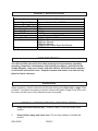
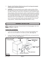
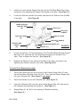
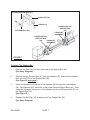
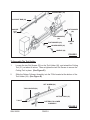
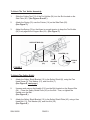
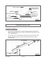
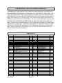
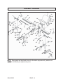
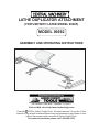
LATHE DUPLICATOR ATTACHMENT
(FOR USE WITH LATHE MODEL 90265)
MODEL 90692
ASSEMBLY AND OPERATING INSTRUCTIONS
®
3491 Mission Oaks Blvd., Camarillo, CA 93011
Visit our Web site at http//www.harborfreight.com
Copyright 2003 by Harbor Freight Tools. All rights reserved. No portion of this
manual or any artwork contained herein may be reproduced in any shape or form
without the express written consent of Harbor Freight Tools.
For technical questions, please call 1-800-444-3353.
PRODUCT SPECIFICATIONS
Item
Product Compatibility
Maximum Turning Length
Maximum Bowl Diameter
Overall Length
Overall Height
Overall Width
Scale
Cutting Tool Dimensions
Accessories
Weight
Description
For use with Lathe Model 90265
38”
8”
40”
7-1/2”
4-5/16”
Inches/Metric – 1/16” & 1MM Segments
0.195” x 0.512” x 7.875”
3MM Hex Wrench
4MM Hex Wrench
6MM Hex Wrench
10MM/12MM Combo Open End Wrench
22.20 Pounds
SAVE THIS MANUAL
You will need this manual for the safety warnings and precautions, assembly,
operating, inspection, maintenance and cleaning procedures, parts list and assembly diagram. Keep your invoice with this manual. Write the invoice number
on the inside of the front cover. Keep this manual and invoice in a safe and dry
place for future reference.
UNPACKING
When unpacking, check to make sure all the parts shown in the Parts List on page 13 are
included. If any parts are missing or broken, please call Harbor Freight Tools at the number shown on the cover of this manual as soon as possible.
GENERAL SAFETY WARNINGS AND PRECAUTIONS
1.
Keep work area clean and dry. Cluttered, damp, or wet work areas invite
injuries.
2.
Keep children away from work area. Do not allow children to handle this
product.
SKU 90692
PAGE 2
3.
Store idle equipment. When not in use, tools and equipment should be stored
in a dry location to inhibit rust. Always lock up tools and equipment, and keep out
of reach of children.
4.
Do not use this product if under the influence of alcohol or drugs. Read
warning labels on prescriptions to determine if your judgement or reflexes are
impaired while taking drugs. If there is any doubt, do not attempt to use this
product.
5.
Maintain labels and nameplates on this product. These carry important
information. If unreadable or missing, contact Harbor Freight Tools for a replacement.
6.
Dress safely. Do not wear loose clothing or jewelry, as they can become caught
in moving parts. Wear a protective hair covering to prevent long hair from becoming caught in moving parts.
7.
Do not overreach. Keep proper footing and balance at all times to prevent
tripping, falling, back injury, etcetera.
8.
Industrial applications must follow OSHA requirements.
9.
Stay alert. Watch what you are doing at all times. Use common sense. Do not
use this product when you are tired or distracted from the job at hand.
10.
Check for damaged parts. Before using this product, carefully check that it will
operate properly and perform its intended function. Check for damaged parts
and any other conditions that may affect the operation of this product. Replace
or repair damaged or worn parts immediately.
11.
Replacement parts and accessories: When servicing, use only
identical replacement parts. Only use accessories intended for use with this
product. Approved accessories are available from Harbor Freight Tools.
12.
Maintain this product with care. Keep this product clean and dry during storage for better and safer performance. For your safety, service and maintenance
should be performed regularly by a qualified technician.
13.
Use the right equipment for the job. Do not attempt to force small equipment
to do the work of a larger industrial tool. There are certain applications for which
this equipment was designed. It will do the job better and more safely at the rate
for which it was intended. Do not modify this equipment, and do not use this
equipment for a purpose for which it was not intended.
14.
WARNING! The warnings, precautions, and instructions discussed in this manual
SKU 90692
PAGE 3
cannot cover all possible conditions and situations that may occur. The operator
must understand that common sense and caution are factors, which cannot be
built into this product, but must be supplied by the operator.
SPECIFIC PRODUCT WARNINGS AND PRECAUTIONS
1.
This Lathe Duplicator Attachment is designed for use ONLY with the Lathe
Model 90265 (available from Harbor Freight Tools). Make sure to read and
understand all instructions and safety precautions as outlined in the manufacturer’s manual for the Model 90265 Lathe with which the Lathe Duplicator
Attachment will be used.
2.
Maintain a safe working environment. Keep the work area well lit. Make sure
there is adequate surrounding workspace. Always keep the work area free of
obstructions, oil, grease, trash, and other debris.
3.
Keep all safety guards in place, in proper adjustment, and in proper alignment.
4.
Prior to starting the Lathe and Lathe Duplicator Attachment, make sure all
adjusting keys and wrenches are removed from the equipment.
5.
Never adjust the Lathe Duplicator Attachment while it is running. Turn off
and unplug the Lathe from its electrical outlet. Wait until the Lathe comes to a
complete stop before performing any adjustments.
6.
Protect hands and fingers from possible injury. Keep hands and fingers
away from the chuck, centers, and other moving parts.
7.
Wear eye, face, and hearing protection. Always wear an ANSI approved full
face safety shield and ANSI approved hearing protectors when using the Lathe
Duplicator Attachment. Wear ANSI approved dust masks or a respirator if the
work performed creates excessive dust.
8.
Never leave the Lathe Duplicator Attachment unattended while it is running.
Turn off the electrical power to the Lathe, and do not leave the Lathe Duplicator
Attachment until the Lathe comes to a complete stop.
9.
Never stand on the Lathe Duplicator Attachment. Serious injury could occur if
the equipment is tipped or if the sharp centers are accidentally contacted.
10.
Keep the Cutting Tool sharp and dry for better and safer performance.
SKU 90692
PAGE 4
11.
Keep the Lathe Duplicator Attachment dry and its moving parts properly
oiled for better and safer performance.
12.
WARNING! Some dust created by power sanding, sawing, grinding, drilling,
lathe operations, and other construction activities, contain chemicals known (to
the State of California) to cause cancer, birth defects or other reproductive harm.
Some examples of these chemicals are: lead from lead-based paints, crystalline
silica from bricks and cement or other masonry products, arsenic and chromium
from chemically treated lumber. Your risk from these exposures varies, depending on how often you do this type of work. To reduce your exposure to these
chemicals: work in a well ventilated area, and work with approved safety equipment, such as those dust masks that are specially designed to filter out microscopic particles. (California Health & Safety Code 25249.5, et seq.)
ASSEMBLY INSTRUCTIONS
NOTE: For additional references to the parts listed in the following pages, refer to the
Assembly Diagram on page 14.
To Attach The Tool Rest Base:
1.
Loosen the Tool Rest Handle of the lathe, and slide the Tool Rest Base of the
lathe to as near the Headstock of the lathe as possible. (See Figure A.)
2.
Loosen the Support Bar Handle of the Model 90265 lathe, and remove the Tool
Rest Base of the lathe. (See Figure A.)
MODEL 90265 LATHE
NOT INCLUDED.
HEADSTOCK
LOWER VERTICAL
SUPPORT BAR
(46)
TOOL REST
HANDLE
TOOL REST BASE
SUPPORT BAR HANDLE
FIGURE A
SKU 90692
PAGE 5
3.
Install one Lower Vertical Support Bar (46) onto the Tool Rest Base of the lathe,
and secure it by tightening the Support Bar Handle of the lathe. (See Figure A.)
4.
Loosen the Tailstock Handle of the lathe, and remove the Tailstock from the Bed
of the lathe.
(See Figure B.)
LOWER VERTICAL
SUPPORT BAR
(46)
TAILSTOCK
TAILSTOCK
HANDLE
BED OF LATHE
TOOL REST BASE
(44)
TOOL REST HANDLE
(55)
SUPPORT BAR
HANDLE
(45)
SUPPORT BAR INSERT (53)
HEX NUT (17)
FIGURE B
5.
Loosen the Hex Nut (17) from the bottom of the Tool Rest Base (44) and Support
Bar Insert (53), and slide the Tool Rest Base assembly onto the Bed of the
lathe. Then, re-tighten the Hex Nut. (See Figure B.)
6.
Replace the Tailstock of the lathe onto the Bed of the lathe, and secure it by
tightening the Tailstock Handle of the lathe. (See Figure B.)
To Install The U-Bracket Assembly:
1.
Screw one Pattern Bolt (42) into the side of one Pattern Support Bar (41) and
secure the Pattern Bolt with a Hex Nut (39). Then, slide the Pattern Support Bar
into one U-Bracket (38). (See Figure C, next page.)
2.
Screw one Handle (3) into the U-Bracket (38). (See Figure C.)
3.
Insert the U-Bracket (38) onto the Lower Vertical Support Bar (46), and secure
the U-Bracket by tightening the Handle (3). (See Figure C.)
4.
Repeat Steps #1, #2, #3 for the remaining U-Bracket Assembly.
(See Figure C.)
SKU 90692
PAGE 6
PATTERN SUPPORT BAR (41)
U-BRACKET (38)
HANDLE (3)
LOWER VERTICAL
SUPPORT BAR
(46)
U-BRACKET
ASSEMBLY
PATTERN BOLT (42)
LOWER VERTICAL
SUPPORT BAR
(46)
U-BRACKET
ASSEMBLY
FIGURE C
To Attach The Support Bar:
1.
Remove the End Cap (12) from each end of the Support Bar (54).
(See Assy. Diagram.)
2.
Remove the two Square Nuts (47) from the Handles (48), and insert the Square
Nuts into the T-Slot of the Support Bar (54).
(See Figure D, next page.)
3.
Insert the threaded, bolt portion of the Handles (48) through the Lockwashers
(34), Flat Washers (40), and holes in the Lower Vertical Support Bars (46). Then,
screw the threaded, bolt portion of the Handles into the two Square Nuts (47) on
the Support Bar (54).
(See Figure D.)
4.
Replace the End Cap (12) on each end of the Support Bar (54).
(See Assy. Diagram.)
SKU 90692
PAGE 7
SQUARE NUT (47)
SUPPORT BAR (54)
SQUARE
NUT
(47)
FLAT WASHER
(40)
LOCKWASHER
(34)
FLAT WASHER (40)
HANDLE
(48)
LOCKWASHER (34)
HANDLE (48)
FIGURE D
To Assemble The Tool Holder:
1.
Loosen the two Set Screws (20) on the Tool Holder (24), and extend the Cutting
Tool (31) out about 4 inches. Then re-tighten the two Set Screws to secure the
Cutting Tool in place. (See Figure E.)
2.
Slide the Pattern Follower Assembly into the T-Slot located at the bottom of the
Tool Holder (24). (See Figure E.)
SET SCREW (20)
TOOL HOLDER (24)
..
CUTTING TOOL (31)
T-SLOT
PATTERN FOLLOWER
ASSEMBLY
FIGURE E
SKU 90692
PAGE 8
To Attach The Tool Holder Assembly:
1.
Slide the Cutting Tool (31) of the Tool Holder (24) into the Slot located on the
Side Plate (50). (See Figures E and F.)
2.
Attach the Spring (19) over the Pointer (14) on the Side Plate (50).
(See Figure F.)
3.
Adjust the Spring (19) so that there is enough tension to keep the Tool Holder
(24) firmly against the Support Bar (54). (See Figure F.)
SUPPORT BAR (54)
POINTER (14)
SLIDE PLATE
(50)
TOOL
HOLDER
(24)
SPRING
(19)
FIGURE F
To Attach The Safety Shield:
1.
Attach the Safety Shield Bracket (10) to the Safety Shield (8), using the Pan
Head Screw (9), Flat Washer (21), and Hex Nut (7).
(See Figure G, next page.)
2.
Unscrew and remove the Handle (51) from the Bolt located on the Support Bar
(54). Place the Safety Shield Plate (43) on the Bolt. Then, re-tighten the
Handle onto the Bolt.
(See Figure G.)
3.
Attach the Safety Shield Bracket (10) to the Safety Shield Plate (43), using a Hex
Head Bolt (11), Flat Washer (40), and Hex Nut (39).
(See Figure G.)
SKU 90692
PAGE 9
SAFETY SHIELD (8)
PAN HEAD SCREW (9)
FLAT WASHER (21)
HANDLE (51)
HEX NUT (7)
SAFETY SHIELD PLATE (43)
HEX HEAD BOLT (11)
FLAT WASHER (40)
HEX NUT (39)
BOLT
SUPPORT BAR (54)
FIGURE G
OPERATING INSTRUCTIONS
To Adjust The Cutting Tool:
1.
Prior to use, the Cutting Tool (31) must be set approximately 1/8” above the
Spindle of the lathe. Make sure to check at the Headstock and Tailstock of the
lathe. (See Figure H.)
2.
The Cutting Tool (31) can be adjusted vertically by loosening the Support Bar
Handles (45) which secure the Lower Vertical Support Bars (46) in place.
(See Figure B.)
SET SCREW (20)
SOCKET HEAD BOLT
(25)
SKU 90692
CUTTING
TOOL
(31)
FIGURE H
PAGE 10
3.
The Cutting Tool (31) also can be adjusted vertically by loosening the Socket
Head Bolt (25) which secures the Tool Holder (24) in place. Once adjusted,
make sure to re-tighten the Socket Head Bolt. (See Figure H.)
4.
The Cutting Tool (31) can be adjusted horizontally by moving the Tool Rest Base
across the Bed of the lathe, towards or away from the Spindle of the lathe.
(See Figure A.)
5.
The Cutting Tool (31) also can be adjusted horizontally by loosening the two Set
Screws (20), moving the Cutting Tool in or out, and then re-tightening the Set
Screws. (See Figure H.)
To Perform Duplicate Turning:
1.
Mount the original woodstock that is to be duplicated in the Pattern Bolts (42).
The Tool Rest Bases (44) will need to be adjusted along the Bed of the lathe to
the required length. (See Figures A, and C.)
2.
Mount the new piece of woodstock in the lathe. When starting with a square
piece of woodstock that will be cut to a cylinder, detach the Spring (19) on the
Tool Holder (24) from the Support Bar (54). Manually feed the Cutting Tool into
the woodstock with a light depth of cut until the cylinder has been formed. Do
not start cutting on the end of the woodstock, as the Cutting Tool may
become caught and damage the woodstock. (See Figure F.)
3.
Turn the woodstock to a cylinder slightly larger than final size. Then, reattach the
Spring from the Tool Holder (24) to the Support Bar (54) and adjust the Pattern
Follower assembly against the original woodstock. (See Figures E, and F.)
4.
Continue gliding the Tool Holder (24) along the Support Bar (54) until the new
piece of woodstock fully duplicates the original piece of woodstock.
(See Figure F.)
5.
Always make sure to turn off the lathe and unplug it from its electrical outlet when
finished with duplicate turning. Wait until the lathe and Lathe Duplicator Attachment stop completely before attempting to remove the pieces of woodstock.
INSPECTION, MAINTENANCE, AND CLEANING
1.
Before each use, inspect the general condition of the Lathe Duplicator Attachment. Check for broken, cracked, or bent parts, loose or missing parts, and any
condition that may affect the proper operation of the product. If a problem
SKU 90692
PAGE 11
occurs, have the problem corrected before further use.
Do not use damaged equipment.
2.
For better and safer performance, always keep the Cutting Tool (31) clean and
sharp.
3.
Daily, with a clean cloth, brush, or vacuum remove all debris fromthe Lathe Duplicator Attachment. Then, use a lightweight machine oil to lubricate all moving
parts.
TROUBLESHOOTING GUIDE
Symptom
Machine slows down
while operating.
Tool “chatters” during
turning operation.
Workpiece splits or
breaks up during
turning operation.
Workpiece finish poor.
SKU 90692
Possible Cause(s)
Corrective Action
1. Applying too much
pressure to workpiece.
1. Workpiece is too
far out of round.
1. Ease up on pressure.
2. Workpiece has too
much wobble.
2. Establish new center
marks on ends to reduce
wobble.
3. Operator using
improper technique.
3. Read instructions, and
take lighter cuts to
minimize chatter.
4. Cutting motion is against
the grain of the workpiece.
4. Use cutting motion that is
with the grain.
5. Workpiece is too long and thin,
and is deflected by tool
pressure.
5. Install a steady rest in the
middle, behind the
workpiece.
1. Workpiece contained defects
before mounting.
1. Select or assemble a
workpiece that is free
of defects.
1. Secure prototype or
template.
1. Prototype or template loose.
1. True up the roundness
of the workpiece before
turning operation.
2. Loose tool holder.
2. Tighten tension of spring.
3.
3.
Pattern follower not
contacting original.
PAGE 12
Adjust pattern follower
firmly against original.
PLEASE READ THE FOLLOWING CAREFULLY
THE MANUFACTURER AND/OR DISTRIBUTOR HAS PROVIDED THE PARTS LIST
AND ASSEMBLY DIAGRAM IN THIS MANUAL AS A REFERENCE TOOL ONLY. NEITHER THE MANUFACTURER OR DISTRIBUTOR MAKES ANY REPRESENTATION
OR WARRANTY OF ANY KIND TO THE BUYER THAT HE OR SHE IS QUALIFIED TO
MAKE ANY REPAIRS TO THE PRODUCT, OR THAT HE OR SHE IS QUALIFIED TO
REPLACE ANY PARTS OF THE PRODUCT. IN FACT, THE MANUFACTUER AND/OR
DISTRIBUTOR EXPRESSLY STATES THAT ALL REPAIRS AND PARTS REPLACEMENTS SHOULD BE UNDERTAKEN BY CERTIFIED AND LICENSED TECHNICIANS,
AND NOT BY THE BUYER. THE BUYER ASSUMES ALL RISK AND LIABILITY ARISING OUT OF HIS OR HER REPAIRS TO THE ORIGINAL PRODUCT OR REPLACEMENT PARTS THERETO, OR ARISING OUT OF HIS OR HER INSTALLATION OF
REPLACEMENT PARTS THERETO.
PARTS LIST
Part #
1
2
3
4
5
6
7
8
9
10
11
12
13
14
15
16
17
18
19
20
21
22
23
24
25
26
27
-----------
SKU 90692
Description
Socket Head Bolt (5/16”-18*1”)
Upper Vertical Support Bar
Handle
Dowel Pin (3*12MM)
Spring Pin (3*10MM)
Square Nut (1/4”-20)
Hex Nut (#10-24)
Safety Shield
Pan Head Screw (#10-24*1/2”)
Bracket
Hex Head Bolt (5/16”x18*3/4”)
Cap (Set of 2)
Flat Head Screw (#10-24*3/8”)
Pointer
Flat Head Screw (#10-24*1/4”)
Scale
Hex Nut
Slide Plate Base
Spring
Set Screw (1/4-20*1/4”)
Flat Washer (#10)
Lock Washer (#10)
Wing Nut (#10-24)
Tool Holder
Socket Head Bolt (#10-24*3/8”)
Bracket
Ball Bearing (R83022)
---------------------------------------------
Qty.
4
2
2
4
1
1
2
1
2
1
1
1
1
1
1
1
2
1
1
2
3
3
1
1
1
1
5
--------
Part #
28
29
30
31
32
33
34
35
36
37
38
39
40
41
42
43
44
45
46
47
48
49
50
51
52
53
54
55
PAGE 13
Description
Rod
Flat Washer (1/4”)
Hex Nut (1/4”-20)
Cutting Tool
Dowel Pin Base
Dowel Pin (3*18.7MM)
Lock Washer (5/16”)
Socket Head Bolt
Socket Head Bolt
Hex Head Bolt
U-Bracket
Hex Nut (5/16”-18)
Flat Washer (5/16”)
Pattern Support Bar
Pattern Bolt
Plate
Tool Rest Base
Handle
Lower Vert. Support Bar
Square Nut (5/16”-18)
Handle
Pan Washer Head Screw
Slide Plate
Handle
Ball (5/16”)
Support Bar Insert
Support Bar
Tool Rest Handle
Qty.
1
1
1
1
1
4
8
4
2
1
2
3
3
2
2
1
1
1
2
2
2
2
1
1
8
1
1
1
ASSEMBLY DIAGRAM
12
8
9
3
49
38
21
54
51
43
53
45
11
52 50
10
2
42
40
41
32
46
19
14
17
16
39
22
7
15
14
38 1 23
22
21
25
20
33
30
5
27
24
12
49
38
18 34
32
35
6
31
29
28
13
39
36
37
3
39
2
41
47
42
26
25
46
34
48
40 1
44
55
45
NOTE: Some parts are listed and shown for illustration purposes only, and are not
available individually as replacement parts.
SKU 90692
PAGE 14