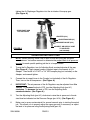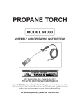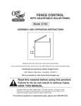
1
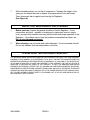
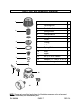
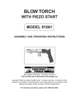
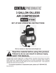
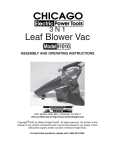
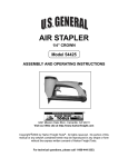
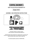
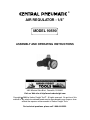
®
AIR REGULATOR - 1/4”
MODEL 90590
ASSEMBLY AND OPERATING INSTRUCTIONS
®
3491 Mission Oaks Blvd., Camarillo, CA 93011
Visit our Web site at http//www.harborfreight.com
Copyright 2003 by Harbor Freight Tools®. All rights reserved. No portion of this
manual or any artwork contained herein may be reproduced in any shape or form
without the express written consent of Harbor Freight Tools.
For technical questions, please call 1-800-444-3353.
PRODUCT SPECIFICATIONS
ITEM
DESCRIPTION
Maximum Pressure
Air Inlet Size
Air Outlet Size
Regulator Type
160 PSI
1/4” NPS
1/4” NPS
Piston Type Regulator Assembly
(for HVLP Gun)
1-5/8” Diameter
Center Back Connection Pressure Gauge
1.15 Lbs.
Pressure Gauge Size
Guage Type
Weight
SAVE THIS MANUAL
You will need this manual for the safety warnings and precautions, assembly,
operating, inspection, maintenance and cleaning procedures, parts list and assembly diagram. Keep your invoice with this manual. Write the invoice number
on the inside of the front cover. Keep this manual and invoice in a safe and dry
place for future reference.
GENERAL SAFETY WARNINGS AND PRECAUTIONS
1.
Do not exceed the maximum pressure rating of 160 PSI for this product.
2.
Keep work area clean and dry. Cluttered, damp, or wet work areas invite
injuries.
3.
Keep children away from work area. Do not allow children to handle this
product.
4.
Store idle equipment. When not in use, tools and equipment should be stored
in a dry location to inhibit rust. Always lock up tools and equipment, and keep out
of reach of children.
SKU 90590
PAGE 2
5.
Do not use this product if under the influence of alcohol or drugs. Read
warning labels on prescriptions to determine if your judgement or reflexes
are impaired while taking drugs. If there is any doubt, do not attempt to use this
product.
6.
Use eye protection. Wear ANSI approved safety impact eye goggles when
using this product. ANSI approved safety impact eye goggles are available from
Harbor Freight Tools.
7.
Dress safely. Do not wear loose clothing or jewelry, as they can become caught
in moving parts. Wear a protective hair covering to prevent long hair from becoming caught in moving parts.
8.
Do not overreach. Keep proper footing and balance at all times to prevent
tripping, falling, back injury, etc.
9.
Industrial applications must follow OSHA requirements.
10.
Stay alert. Watch what you are doing at all times. Use common sense. Do not
use this product when you are tired or distracted from the job at hand.
11.
Check for damaged parts. Before using this product, carefully check that it will
operate properly and perform its intended function. Check for damaged parts
and any other conditions that may affect the operation of this product. Replace
or repair damaged or worn parts immediately.
12.
Replacement parts and accessories: When servicing, use only identical replacement parts. Only use accessories intended for use with this product. Approved accessories are available from Harbor Freight Tools.
13.
Maintain this product with care. Keep this product clean and dry for better and
safer performance. For your safety, service and maintenance should be performed regularly by a qualified technician.
14.
Use the right tool for the job. Do not attempt to force a small tool to do the
work of a larger industrial tool. There are certain applications for which this tool
was designed. It will do the job better and more safely at the capacity for which it
was intended. Do not modify this tool, and do not use this tool for a purpose for
which it was not intended.
15.
Maintain a safe working environment. Keep the work area well lit. Make sure
there is adequate surrounding work space. Always keep the area free of obstructions, grease, oil, trash, and other debris. Use this product only in a well ventilated area.
SKU 90590
PAGE 3
16.
Before each use, always check all connections and joints to make sure no
air leaks are present. Also check air hoses for cracks or excessive wear.
Always replace a damaged hose.
17.
Maintain labels and nameplates on this product. These carry important
information. If unreadable or missing, contact Harbor Freight Tools for a replacement.
18.
Always disconnect the Air Regulator from its air supply source before
performing any maintenance on the Air Regulator.
19.
WARNING! The brass components of this product contain lead, a chemical
known to the State of California to cause birth defects (or other reproductive
harm). (California Health & Safety Code 25249.5, et seq.)
20.
Always read and adhere to all safety warnings and instructions provided in
the instruction manual of the spray paint equipment being used.
21.
WARNING! The warnings, precautions, and instructions discussed in this
manual cannot cover all possible conditions and situations that may occur. The
operator must understand that common sense and caution are factors, which
cannot be built into this product, but must be supplied by the operator.
UNPACKING
When unpacking, check to make sure all the parts shown on the Parts List (page 7) are
included. If any parts are missing or broken, please call Harbor Freight Tools at the
number shown on the cover of this manual as soon as possible.
PRODUCT DESCRIPTION
1.
The Air Regulator is designed for use on paint spray guns. The Regulator’s stop
feature prevents surges while spraying to keep an even coat and improve the
paint finish.
ASSEMBLY INSTRUCTIONS
NOTE: For additional references to the parts listed on the following pages, refer to the
Assembly Diagram (page 7).
1.
Proper use of the Air Regulator requires that it be directly attached to the air
intake of the spray gun. To do so, wrap about 3” of pipe thread seal tape (not
included) around the male threads of the Spray Gun. Then, wrench
SKU 90590
PAGE 4
tighten the Air Diaphragm Regulator into the air intake of the spray gun.
(See Figure A.)
SPRAY PAINT GUN
NOT INCLUDED.
ADAPTER (#13)
ADJUSTING KNOB (#1)
PRESSURE GAUGE (#14)
CONNECT AIR SUPPLY HOSE
TO COUPLER
(not included)
FIGURE A
OPERATING INSTRUCTIONS
1.
NOTE: Before starting, make sure to refer to both the spray gun and paint
manufacturers’ instruction manuals to determine the proper level of air pressure
required for each specific painting job that is to be performed.
2.
To use the Air Regulator, turn its Adjusting Knob counterclockwise all the way.
(See Figure A.) Apply several wraps of sealant tape to the threads of #13
Adapter. Then install a 1/4” NPT or 1/4” NPS coupler plug (not included) on the
Adapter, and wrench tighten.
3.
Connect the air supply hose to the Coupler (not included) of the Air Regulator.
Then, turn on the air compressor. (See Figure A.)
4.
IMPORTANT: The air pressure of the Air Regulator may be adjusted from 0 to
160 PSI. To increase the level of PSI, turn the Adjusting Knob (part #1)
clockwise. To decrease the level of PSI, turn the Adjusting Knob
counterclockwise. (See Figure A.)
5.
Turn the Adjusting Knob (part #1) clockwise to raise the air pressure to the desired level as indicated on the Pressure Gauge (part #14). (See Figure A.)
6.
Make sure to spray waste material for several seconds prior to starting the actual
job. This allows you to properly adjust the spray gun and, if necessary, re-adjust
the level of air pressure using the Adjusting Knob (part #1).
SKU 90590
PAGE 5
7.
When finished painting, turn off the air compressor. Squeeze the trigger of the
spray gun for several seconds to release all compressed air from the system.
Then, disconnect the air supply hose from the Air Regulator.
(See Figure A.)
INSPECTION, MAINTENANCE, AND CLEANING
1.
Before each use, inspect the general condition of the Air Regulator. loose
connections and joints, cracked, or broken parts, excessively worn air supply
hose, and any other condition that may affect the safe and proper operation of the
Regulator. If a problem occurs, have the problem corrected before further use.
Do not use damaged equipment.
2.
When cleaning, use only water and a mild detergent. Do not immersed in liquid.
Do not use cleaners that are combustible or corrosive.
PLEASE READ THE FOLLOWING CAREFULLY
THE MANUFACTURER AND/OR DISTRIBUTOR HAS PROVIDED THE PARTS LIST AND ASSEMBLY
DIAGRAM IN THIS MANUAL AS A REFERENCE TOOL ONLY. NEITHER THE MANUFACTURER OR
DISTRIBUTOR MAKES ANY REPRESENTATION OR WARRANTY OF ANY KIND TO THE BUYER THAT
HE OR SHE IS QUALIFIED TO MAKE ANY REPAIRS TO THE PRODUCT, OR THAT HE OR SHE IS
QUALIFIED TO REPLACE ANY PARTS OF THE PRODUCT. IN FACT, THE MANUFACTUER AND/OR
DISTRIBUTOR EXPRESSLY STATES THAT ALL REPAIRS AND PARTS REPLACEMENTS SHOULD BE
UNDERTAKEN BY CERTIFIED AND LICENSED TECHNICIANS, AND NOT BY THE BUYER. THE BUYER
ASSUMES ALL RISK AND LIABILITY ARISING OUT OF HIS OR HER REPAIRS TO THE ORIGINAL PRODUCT OR REPLACEMENT PARTS THERETO, OR ARISING OUT OF HIS OR HER INSTALLATION OF
REPLACEMENT PARTS THERETO.
SKU 90590
PAGE 6
PARTS LIST AND ASSEMBLY DIAGRAM
1
PART #
2
3
4
5
6
7
8
DESCRIPTION
QTY
1
Adjusting Knob
1
2
Regulation Spring
1
3
Spring Washer
1
4
Umbrella Baffle
1
5
O-Ring
1
6
Holder
1
7
O-Ring
1
8
Baffle
1
9
Spring Washer
1
10
Body
1
11
Nipple
1
12
Nut (1/4” N.P.S. Female)
1
13
Adapter (1/8”-14M) x 1/4” N.P.S.
1
14
Pressure Gauge
1
9
10
11
12
14
13
NOTE: Some parts are listed and shown for illustration purposes only, and are not
available individually as replacement parts.
REV 07k
SKU 90590
PAGE 7