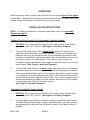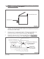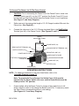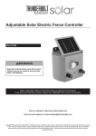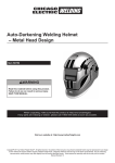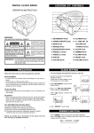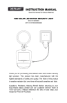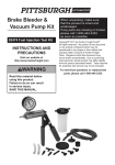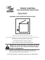
1
FENCE CONTROL
WITH ADJUSTABLE SOLAR PANEL
Model 47454
ASSEMBLY AND OPERATING INSTRUCTIONS
Diagrams within this manual may not be drawn proportionally.
Due to continuing improvements, actual product may differ slightly from the product described herein.
Distributed exclusively by Harbor Freight Tools®.
3491 Mission Oaks Blvd., Camarillo, CA 93011
Visit our website at: http://www.harborfreight.com
Read this material before using this product.
Failure to do so can result in serious injury.
Save this manual.
Copyright© 2002 by Harbor Freight Tools®. All rights reserved. No portion of this
manual or any artwork contained herein may be reproduced in any shape or form
without the express written consent of Harbor Freight Tools.
For technical questions or replacement parts, please call 1-800-444-3353.
SPECIFICATIONS TABLE
ITEM
DESCRIPTION
Input Voltage
Output Voltage
Battery Type
Range of Fence Control
Solar Panel Type
Solar Panel Size
Rated Wattage In Full Sunlight
Overall Dimensions
Weight
8.7 VDC
8 KV +/- 1.5 KV
6 Volt, DC, Lead Acid, 4.5 AH
3 to 5 Miles (Single Strand Wire)
Angle Adjustable
4-1/4” x 3-3/4”
1.3 Watts
7-1/4” x 6-7/8” x 5-3/8”
3.65 Lbs.
SAVE THIS MANUAL
You will need this manual for the safety warnings and precautions, assembly, operating, inspection, maintenance and cleaning procedures, parts list and assembly
diagram. Keep your invoice with this manual. Write the invoice number on the inside
of the front cover. Keep this manual and invoice in a safe and dry place for future
reference.
PRODUCT OVERVIEW
The Fence Control is designed to keep only animals confined to a specific area by
emitting an electrical shock. Do not use this product for any other purpose.
GENERAL SAFETY WARNINGS AND PRECAUTIONS
1.
KEEP WORK AREA CLEAN AND DRY. Cluttered, damp, or wet work areas
invite injuries.
2.
KEEP CHILDREN AWAY FROM WORK AREA. Do not allow children to handle
this product.
3.
STORE IDLE EQUIPMENT. When not in use, tools and equipment should be
stored in a dry location to inhibit rust. Always lock up tools and equipment, and
keep out of reach of children.
4.
DO NOT USE THIS PRODUCT IF UNDER THE INFLUENCE OF ALCOHOL OR
DRUGS. Read warning labels on prescriptions to determine if your judgement or
reflexes are impaired while taking drugs. If there is any doubt, do not attempt to
use this product.
5.
USE EYE PROTECTION. Wear ANSI approved safety impact eyeglasses when
using this product. ANSI approved safety impact eyeglasses are available from
Harbor Freight Tools.
6.
INDUSTRIAL APPLICATIONS MUST FOLLOW OSHA REQUIREMENTS.
REV 08e
SKU 47454
PAGE 2
7.
STAY ALERT. Watch what you are doing at all times. Use common sense. Do
not use this product when you are tired or distracted from the job at hand.
8.
CHECK FOR DAMAGED PARTS. Before using this product, carefully check that
it will operate properly and perform its intended function. Check for damaged
parts and any other conditions that may affect the operation of this product.
Replace or repair damaged or worn parts immediately.
9.
REPLACEMENT PARTS AND ACCESSORIES: When servicing, use only
identical replacement parts. Only use accessories intended for use with this
product. Approved accessories are available from Harbor Freight Tools.
10.
MAINTAIN THIS PRODUCT WITH CARE. Keep this product clean for better and
safer performance.
11.
MAINTENANCE: For your safety, service and maintenance should be performed
regularly by a qualified technician.
12.
USE THE RIGHT TOOL FOR THE JOB. Do not attempt to force a small tool or
attachment to do the work of a larger industrial tool. There are certain
applications for which this tool was designed. It will do the job better and more
safely at the rate for which it was intended. Do not modify this tool, and do not
use this tool for a purpose for which it was not intended.
13.
WARNING: The warnings, precautions, and instructions discussed in this manual
cannot cover all possible conditions and situations that may occur. The operator
must understand that common sense and caution are factors, which cannot be
built into this product, but must be supplied by the operator.
SPECIFIC PRODUCT WARNINGS AND PRECAUTIONS
1.
CAUTION: FOR PERSONAL SAFETY, IT IS RECOMMENDED THAT ONLY A
QUALIFIED, CERTIFIED ELECTRICIAN INSTALL THE FENCE CONTROL.
2.
MAINTAIN A SAFE WORKING ENVIRONMENT. Keep the work area well lit.
Make sure there is adequate surrounding workspace. Always keep the work area
free of obstructions, grease, oil, trash, and other debris. Do not use the Fence
Control in areas near flammable chemicals, dusts, and vapors.
3.
THIS PRODUCT MUST BE GROUNDED. If for any reason the Fence Control
should malfunction, grounding reduces the risk of accidental electrical shock. A
properly installed ground rod (not provided) electrically connected to the Fence
Control ground terminal provides the necessary grounding of this product.
(See Figure B.)
REV 07g
SKU 47454
PAGE 3
4.
DO NOT CONNECT ANY OTHER DEVICE, SUCH AS A POULTRY OR CATTLE
TRAINER, TO A FENCE THAT IS ALREADY CONNECTED TO THE FENCE
CONTROL. Should lightening strike the fence, its damaging electrical force will
be conducted to all other devices.
5.
AVOID ACCIDENTAL ELECTRICAL SHOCK. Never install an electric fence
below high voltage power plant transmission lines. Never touch or attempt to
climb over a fence that is electrically charged. Never use more than one Fence
Control on the same fence. Install “Danger! Electric Fence! Risk of Electrical
Shock if Touched!” signs in visible areas to identify the electrified wires. Inform
everyone who might possibly come in contact with the electrically charged fence
about its location. Instruct everyone who might possibly come in contact with the
electrically charged fence how to disconnect the Fence Control in case of
emergency.
6.
FOR INCREASED PICKUP OF SOLAR ENERGY, select a location with full,
direct sunlight, where the Fence Control can receive at least eight hours of
sunlight each day. Shadowed locations will not allow the Battery (part #10) to
fully charge, and will reduce the hours of effective operation. Make sure to adjust
the Solar Panel (part #2) so that it faces directly at the sun at noontime each day
of the year. (See Figure A, and Assy. Diagram.)
7.
ALWAYS KEEP THE SOLAR PANEL (part #2) CLEAN.
(See “Inspection, Maintenance, And Cleaning” section.)
8.
DO NOT USE ANY MEANS OF CHARGING THE BATTERY (part #10) OTHER
THAN THE SOLAR PANEL (part #2) OR A CONSTANT-POTENTIALCURRENT-LIMITED BATTERY CHARGER RATED AT 6V DC @ 4.5 AMPS
PER HOUR.
9.
DO NOT OVERCHARGE THE BATTERY (part #10) WHEN USING A
CONSTANT-POTENTIAL-CURRENT-LIMITED BATTERY CHARGER. To use a
battery charging system other than the Solar Panel (part #2), the Battery must be
removed from the Fence Control. (See Figure C, and Assy. Diagram.)
10.
DO NOT DISPOSE OF BATTERY (part #10) BY FIRE. Fire or intense heat can
cause an explosion. After the life of the Battery has expired, it should be
recycled or disposed of in accordance with procedures for the proper disposal of
waste products.
11.
12.
WARNING: This product contains or produces a chemical known to the State of
California to cause cancer and birth defects (or other reproductive harm).
(California Health & Safety Code 25249.5 et seq.)
WARNING: People with pacemakers should consult their physician(s) before
using this product. Operation of electrical equipment in close proximity to a heart
pacemaker could cause interference or failure of the pacemaker.
SKU 47454
PAGE 4
UNPACKING
When unpacking, check to make sure all the parts shown on the Parts List on page 11
are included. If any parts are missing or broken, please call Harbor Freight Tools at the
number shown on the cover of this manual as soon as possible.
INSTALLATION INSTRUCTIONS
NOTE: For additional references to the parts listed below, refer to the Assembly
Diagram on page 11.
To Mount The Fence Control On A Horizontal Or Vertical Surface:
1.
CAUTION: Prior to mounting the Fence Control, make sure its Power Switch
(part #5) is in the “OFF” position. (See Figure C, and Assy. Diagram.)
2.
To mount the Fence Control onto a wood surface, place the Fence Control
against the desired location on the wood surface. Use the two mounting holes
located at the top of the Main Body (part #4) as a template with which to mark
two holes to be drilled into the wood surface. Set aside the Fence Control, and
drill the two holes in the wood surface. Then, use two wood screws (not
provided) of appropriate diameter and length to secure the Fence Control to the
wood surface. (See Figure A, and Assy. Diagram.)
3.
To mount the Fence Control to a metal surface, place the Fence Control against
the desired location on the metal surface. Use the two mounting holes located
at the top of the Main Body (part #4) as a template with which to mark two holes
to be drilled all the way through the metal surface. Set aside the Fence Control,
and drill the two holes through the metal surface. Then, use two machine bolts of
appropriate diameter and length, two lock washers, and two nuts (not provided)
to secure the Fence Control to the metal surface.
(See Figure A, and Assy. Diagram.)
To Properly Ground The Fence Control:
1.
CAUTION: Prior to grounding the Fence Control, make sure its Power Switch
(part #5) is in the “OFF” position. (See Figure C, and Assy. Diagram.)
2.
A Ground Rod (not provided) is required to properly ground the Fence Control.
A Ground Rod should be made of copper, galvanized pipe, or a steel rod driven approximately six to eight feet into the ground as near to the Fence Control as possible.
SKU 47454
PAGE 5
3.
Caution: Do not use an existing Ground Rod that is hooked up to other electrical
systems or to a water pipe. (See Figure B.)
MOUNTING HOLES
MAIN BODY (#4)
FIGURE A
4.
The front side of the solar shock (with terminals and switch/key) should face the
sun light. The solar panel should face towards south to expose the solar panel to
the maximum possible sunlight.
5.
Connect one end of an appropriate length of 12 Gauge Insulated Wire to the
Ground Rod, using a Ground Clamp (not provided). (See Figure B.)
6.
Connect the other end of the 12 Gauge Insulated Wire to the Black/Negative
Terminal (part #6) of the Fence Control. (See Figures B, and C.)
RED/POSITIVE TERMINAL (#6)
BLACK/NEGATIVE TERMINAL (#6)
12 GA. INSULATED WIRE
(NOT PROVIDED)
12 GA. INSULATED WIRE
(NOT PROVIDED)
FENCE WIRE
GROUND ROD
GROUND CLAMP
(NOT PROVIDED)
FIGURE B
SKU 47454
PAGE 6
To Connect The Fence Line To The Fence Control:
1.
CAUTION: Prior to connecting the Fence Line to the Fence Control, make sure
its Power Switch (part #5) is in the “OFF” position (the Switch Cover [#13] must
be removed from the Power Switch when the Fence Control is not in operation).
(See Figure C, and Assy. Diagram.)
2.
Splice one end of an appropriate length of 12-1/2 Gauge Insulated Wire onto the
Fence Line. (See Figure B.)
3.
Connect the other end of the 12-1/2 Gauge Insulated Wire to the Red/Positive
Terminal (part #6) of the Fence Control. (See Figures B, and C.)
ANGLE
ADJUSTING FRAME
(#3)
FIGURE C
SOLAR PANEL (#2)
RED/POSITIVE TERMINAL (#6)
BLACK/NEGATIVE TERMINAL (#6)
Switch Cover (#13)
INDICATING LAMP (#7)
POWER SWITCH (#5)
RED/POSITIVE WIRE
BATTERY COMPARTMENT
DOOR (#11)
BLACK/NEGATIVE WIRE
MAIN BODY (#4)
BATTERY (#10)
SCREW (#12)
OPERATING INSTRUCTIONS
NOTE: For additional references to the parts listed below, refer to the
Assembly Diagram on page 11.
Note: To operate the Fence Control, the Switch Cover (#13) must be
inserted into the Power Switch (#5) cover and the Power Switch must be lifted up to the “ON” position.
1.
Once installed, allow the Fence Control to charge at least eight hours in full,
direct sunlight in order to fully charge the Battery (part #10). If necessary, adjust
the Solar Panel to increase the pickup of solar energy.
(See Figures A, C, and Assy. Diagram.)
SKU 47454
PAGE 7
NOTE: After making sure that all safety warnings and precautions (pages 2-4) are
adhered to, the Fence Control is ready to be turned ON.
2.
When the Battery (part #10) is fully charged, place the Switch Cover (#13) on the
Power Switch (#5) and turn the Power Switch (part #5) to its “ON” position. (See
Figure C, and Assy. Diagram.)
3.
Observe the Indicating Lamp (part #7). A blinking Indicating Lamp shows that the
electrical output is working properly. The fence is now electrically activated.
(See Figure C, and Assy. Diagram.)
4.
NOTE: If the Indicating Lamp does not blink, turn the Power Switch (part #5)
to its “OFF” position. Have a qualified, certified electrician disconnect both 12
Gauge Insulated Wires from the Fence Control. Then, turn the Power Switch to
its “ON” position. If the Indicating Lamp does blink, the problem is with the fence.
If the Indicating Lamp does not blink, the problem is with the Fence Control or its
Battery (part #10). (See Figures B, C, and Assy. Diagram.)
RECOMMENDED ASSOCIATED ELECTRIC FENCE PRODUCTS
1.
CAUTION: For personal safety, it is recommended that only a qualified, certified,
electrician install electrical products.
Posts:
1.
Use posts made of treated wood, steel, aluminum, or fiberglass.
Fence Wire:
1.
Use size 20 through 9 American wire gauge. Use a smooth, galvanized steel
electric fence wire. Or use an aluminum wire which conducts electricity four
times better than steel. Or in certain cases, use a plastic/metallic wire according
to the manufacturer’s recommendations.
Insulated Wire:
1.
Use size 12 Gauge for running under roads and under gates. If desired, use
insulated wire with PVC tubing.
Insulators:
1.
Use standard Fi-Shock insulators on rod-type line support posts, or on wooden
posts. At the starting point, and at fence corners, use Fi-Shock corner post
insulators. Always insulate wooden posts. Do not staple fence wire directly to the
post.
SKU 47454
PAGE 8
Splices:
1.
Two types of splicing may be used; hand splicing, or the use of specially
designed splicing bolts and connectors.
Gates:
1.
A simple gate can be constructed from a single “hot” wire line with the use of an
insulated gate handle. However, disconnecting the gate handle also disconnects
the electric flow in the fence. A typical gate can be used without interfering with
the electric flow in the fence by running an insulated wire under the gate, beneath
the ground level. A “hot” wire line may be mounted on a typical gate itself to
prevent animals from rubbing or pushing through the gate.
INSPECTION, MAINTENANCE, AND CLEANING
1.
CAUTION: Always turn the Power Switch (part 5) to its “OFF” position and
remove the Switch Lock (#13) before performing any inspection, maintenance, or
cleaning. (See Assy. Diagram.)
2.
BEFORE EACH USE, inspect the general condition of the Fence Control. Check
to make sure that the “Danger! Electric Fence! Risk of Electrical Shock
if Touched!” signs are still up and visible in areas to identify the electrified
wires. Check for loose, cracked or broken parts, loose or damaged electrical
connections, and any other condition that may affect the safe operation of this
equipment. If a problem occurs, immediately turn the Power Switch (part #5) to
its “OFF” position and remove the Switch Lock (#13). Have the problem corrected
by a qualified, certified electrician before further use.
Do not use damaged equipment.
3.
TO REMOVE THE BATTERY (part #10) FOR RECHARGING OR
REPLACEMENT: To use a battery charging system other than the Solar Panel
(part #2), the Battery must be removed from the Fence Control. CAUTION:
Do not use any means of charging the Battery other than the Solar Panel or a
constant-potential-current-limited charger rated at 6V DC @ 4.5 Amps per hour.
To
remove the Battery, loosen and remove the Screw (part #12) that is located at the
rear of the Fence Control. Open the Battery Compartment Door (part #11). Pull
the Battery out of the unit, and disconnect the Black wire that is connected to the
“negative” battery pole. Then, disconnect the Red wire that is connected to the
“positive” battery pole. Follow the battery charger manufacturer’s instructions to
fully charge the Battery. Once the Battery is fully charged, re-connect the Black
wire to the “negative” pole of the Battery, and reconnect the Red wire to the
“positive” pole of the Battery. Reinstall the Battery in the Fence Control unit,
and close the Battery Compartment Door. Finally, replace the Screw to lock the
Battery Compartment Door in position. (See Figure C.)
PERIODICALLY: Inspect the fence line and remove vines, brush, growth, and
fallen branches that will short out the fence.
SKU 47454
PAGE 9
4.
5.
TROUBLESHOOTING: If the fence is not operating properly, make sure nothing,
other than the fence posts, is touching the fence. Make sure all connections to
the Fence Control are clean and tightened securely. Ensure that all fence wires
and the ground wire connections are tightened securely. If necessary, use a
commercial electric fence tester to check the output on the fence line.
6.
TO CLEAN: wipe the outer body of the Fence Control with a soft, damp cloth,
using a mild detergent. Always keep the Solar Panel (part #2) clean, but do not
use an abrasive cleaning pad or cleaning agent that might damage the Solar
Panel glass. (See Assy. Diagram.)
7.
WHEN NOT IN USE AND BEING STORED: Keep the Fence Control in a clean,
dry location.
PLEASE READ THE FOLLOWING CAREFULLY
THE MANUFACTURER AND/OR DISTRIBUTOR HAS PROVIDED THE PARTS LIST AND ASSEMBLY
DIAGRAM IN THIS MANUAL AS A REFERENCE TOOL ONLY. NEITHER THE MANUFACTURER OR
DISTRIBUTOR MAKES ANY REPRESENTATION OR WARRANTY OF ANY KIND TO THE BUYER THAT
HE OR SHE IS QUALIFIED TO MAKE ANY REPAIRS TO THE PRODUCT, OR THAT HE OR SHE IS
QUALIFIED TO REPLACE ANY PARTS OF THE PRODUCT. IN FACT, THE MANUFACTUER AND/OR
DISTRIBUTOR EXPRESSLY STATES THAT ALL REPAIRS AND PARTS REPLACEMENTS SHOULD
BE UNDERTAKEN BY CERTIFIED AND LICENSED TECHNICIANS, AND NOT BY THE BUYER. THE
BUYER ASSUMES ALL RISK AND LIABILITY ARISING OUT OF HIS OR HER REPAIRS TO THE
ORIGINAL PRODUCT OR REPLACEMENT PARTS THERETO, OR ARISING OUT OF HIS OR HER
INSTALLATION OF REPLACEMENT PARTS THERETO.
SKU 47454
PAGE 10
PARTS LIST / ASSEMBLY DIAGRAM
13
Switch Cover
1
13
NOTE: Some parts are listed and shown for illustration purposes only, and are not available individually as replacement parts.
SKU 47454
PAGE 11