1
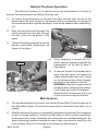
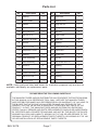
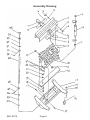
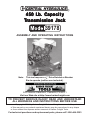
450 Lb. Capacity
Transmission Jack
39178
ASSEMBLY AND OPERATING INSTRUCTIONS
Note:
This tool requres a 1/2” Drive Ratchet or Breaker
Bar to operate (neither one included).
3491 Mission Oaks Blvd., Camarillo, CA 93011
Visit our Web site at http://www.harborfreight.com
TO PREVENT SERIOUS INJURY, READ AND UNDERSTAND
ALL WARNINGS AND INSTRUCTIONS BEFORE USE.
Copyright© 2004 by Harbor Freight Tools®. All rights reserved. No portion
of this manual or any artwork contained herein may be reproduced in any shape
or form without the express written consent of Harbor Freight Tools.
For technical questions and replacement parts, please call 1-800-444-3353
Specifications
Maximum Load
Capacity
450 lbs.
Cradle Size
6-7/8" x 13"
Lift Range
7-1/4" to 22-1/2"
Leadscrew
Thread
5/8" diameter
acme thread type
Swivel Casters
Non-marring
Ball Bearing
Nylon Strap
2" wide x 43" long
Net Weight
33.25 lbs.
Overall Size
16-1/2" x 15-5/8" x 8"
Note:
This tool requres a 1/2” Drive Ratchet or Breaker Bar to operate
(neither one included).
Save This Manual
You will need the manual for the safety warnings and precautions, assembly
instructions, operating and maintenance procedures, parts list and diagram. Keep
your invoice with this manual. Write the invoice number on the inside of the front
cover. Keep the manual and invoice in a safe and dry place for future reference.
Safety Warnings and Precautions
WARNING: When using tool, basic safety precautions should always be followed
to reduce the risk of personal injury and damage to equipment.
Read all instructions before using this tool!
1.
Keep work area clean. Cluttered areas invite injuries.
2.
Observe work area conditions. Do not use machines or power tools in
damp or wet locations. Don’t expose to rain. Keep work area well lighted.
3.
Keep children away. Children must never be allowed in the work area. Do
not let them handle machines, tools, or extension cords.
4.
Store idle equipment. When not in use, tools must be stored in a dry
location to inhibit rust. Always lock up tools and keep out of reach of children.
5.
Use the right tool for the job. Do not attempt to force a small tool or
attachment to do the work of a larger industrial tool. There are certain
applications for which this tool was designed. It will do the job better
and more safely at the rate for which it was intended. Do not modify this
tool and do not use this tool for a purpose for which it was not intended.
6.
Dress properly. Do not wear loose clothing or jewelry as they can be caught
in moving parts. Protective, clothes and non-skid footwear are recommended
when working. Wear restrictive hair covering to contain long hair.
SKU 39178
Page 2
7.
Use eye and ear protection. Always wear ANSI approved impact safety
goggles. Wear an ANSI approved dust mask or respirator when working
around metal, wood, and chemical dusts and mists.
8.
Do not overreach. Keep proper footing and balance at all times. Do not reach
over or across running machines.
9.
Maintain tools with care. Keep tools sharp and clean for better and safer
performance. Follow instructions for lubricating and changing accessories.
The handles must be kept clean, dry, and free from oil and grease at all
times.
10. Remove adjusting keys and wrenches. Check that keys and adjusting
wrenches are removed from the tool or machine work surface before
operating.
11. Avoid unintentional lowering. Keep feet and hands away from the pump
pedal and release pedal when you are not prepared to raise or lower the jack.
12. Stay alert. Watch what you are doing, use common sense. Do not operate
any tool when you are tired.
13. Check for damaged parts. Before using any tool, any part that appears
damaged should be carefully checked to determine that it will operate
properly and perform its intended function. Check for alignment and binding
of moving parts; any broken parts or mounting fixtures; and any other
condition that may affect proper operation. Any part that is damaged should
be properly repaired or replaced by a qualified technician.
14. Replacement parts and accessories. When servicing, use only identical
replacement parts. Use of any other parts will void the warranty. Only use
accessories intended for use with this tool. Approved accessories are
available from Harbor Freight Tools.
15. Do not operate tool if under the influence of alcohol or drugs. Read
warning labels on prescriptions to determine if your judgment or reflexes are
impaired while taking drugs. If there is any doubt, do not operate the tool.
16. Maintenance. For your safety, service and maintenance should be performed
regularly by a qualified technician.
17. Do not exceed the weight limit of this jack. Overloading the jack may result
in unexpected, rapid lowering of the object being held, as well as damage to
the jack itself. Serious injury and property damage may result.
18. Assure that any load being supported by this jack is well balanced.
Unbalanced loads may cause the jack to fall over potentially causing serious
personal injury or property damage.
SKU 39178
Page 3
19. This jack is not to be used for any aircraft purposes.
20. Jack to be used on a flat, level surface capable of supporting the weight of
the jack, the workpiece and related tools
Warning: The warnings, cautions, and instructions discussed in this instruction
manual cannot cover all possible conditions and situations that may occur. It
must be understood by the operator that common sense and caution are factors which cannot be built into this product, but must be supplied by the operator.
Unpacking
When unpacking, check to make sure the following parts are included.
(1) Jack Assembly
(4) Caster Wheel Sets with hardware
If any parts are missing or broken, please call Harbor Freight Tools at the number
on the cover of this manual.
Assembly
Prepare for assembly by having a clean, well lit location. You will need a small
open-end or adjustable wrench (not included) to complete assembly.
1)
Locate the four Casters Assemblies (16), four Nuts (14) and four Spring
Washers (15). Attach a Caster to each of the legs on the Base Assembly (13)
using these as shown in the Assembly Diagram. Tighten securely.
WARNING: Do not overload this jack. The jack may be damaged, and you
may experience unplanned, rapid lowering of the load. This may cause
severe personal injury or property damage.
WARNING: Do not carry an unbalanced load, or a load not appropriate to the
designed use of this jack. The jack may topple over causing serious
personal injury or property damage.
WARNING: Be aware of dynamic loading! A sudden start or jerk on the jack may
create for a brief instant, an excess load, which may result in damage to
the product and/or personal injury.
SKU 39178
Page 4
Operation
WARNING: Before standing or working underneath any elevated vehicle or other object,
be sure that the vehicle is properly and safely secured following recommendations of
the lift manufacturer. For your safety and the safety of others, use good professional
practice and common sense. Only use on a flat, level surface capable of supporting
the weight of the jack, the workpiece and related tools.
1)
The jack may easily be moved by rolling it on its casters. Locate the jack under
the transmission. Using a 1/2” Drive Ratchet or Breaker Bar (neither one included)
engaged in Bushing (35), rotate the Screw Rod (29) clockwise in order to raise
the jack until the Saddle (3) nearly contacts the underside of the transmission.
Adjust the position of the jack so that it is centered directly under the center of
gravity of the transmission.
2)
It is important for your safety to get a good contact between the Saddle (3) and
the transmission. This will assure that the transmission is properly supported
and balanced once removed from the vehicle and on the jack. Loosen the Wing
Nuts (5) and raise the jack again until the Saddle (3) contacts the transmission
and presses slightly against it.
3)
Secure the transmission to the Saddle (3) by passing the Ratchet Tie-down (7)
over the top of the transmission, and securing it using the buckle. Be sure that
it is tight. Please review section on Ratchet Tie-down operation next page. Tighten
the Wing Nuts (5) and raise the jack until the transmission’s weight is supported
by it.
4)
Remove the bolts and fittings attaching the transmission to the vehicle, as
recommended by the vehicle’s repair instructions.
5)
Lower the transmission slightly by turning the Bushing (35) counterclockwise.
Recheck the transmission to assure that it is securely and safely attached to
the Saddle (3). Make any necessary adjustments. When it is safe to do so, lower
the transmission all the way by turning the Bushing (35). For safety, 2 people
should be working together to perform these operations.
6)
While stabilizing the transmission on the jack, roll the transmission out from
under the vehicle to the work location where it will be repaired. It is a good idea
to have an assistant help you lower and move the transmission.
WARNING: The use of this jack is limited to the removal, installation, and transportation in
the lowest position, of transmissions and differentials. Do not store the transmission or any
other part on the jack,unless the jack is in the lowered position. However, the jack is not
appropriate as a long-term storage device. Never move the jack unless it is in its lowest
position.
Do not overload. Overloading can cause damage to the jack and cause consequential
personal or property injury. This jack is designed to use only on hard, level surfaces capable
of supporting the load. Use on other surfaces may cause instability and possible property
damage or personal injury.
SKU 39178
Page 5
Ratchet Tie-down Operation
The Ratchet Tie-down (7) is used to secure the transmission to the jack to
prevent the transmission from falling off during use.
1)
To secure the transmission to the jack, first pass the belt over the top of the
transmission. Be sure the belt is not twisted, and is not pressing on any part of
the transmission that might be damaged, such as the speedometer cable fitting,
etc.
2)
Pass the end of the belt through the
ratchet behind the reel, and through
the slot in the reel, as shown in the
photo.
3)
Tighten the belt by pressing the ratchet
handle repeatedly downward, as
shown in the photo.
4)
When preparing to remove the Tiedown, have an assistant stabilize the
transmission on the jack to keep it
from falling.
5)
To remove the belt: Pull release tab A
away from the spool and swing the
upper handle wide open until it rests
on the raised portion of the flanges,
as shown in the photo to the left.
WARNING: Keep your fingers clear of
the spool when releasing the ratchet;
it will rotate as the belt is released.
When the belt is loosened, pull it out
of the buckle and remove the belt.
Flange
Release Tab A
Release Tab B
Maintenance
1)
The mechanical parts of the jack, such as the Screw Rod (29) and hinge pins of
the Adjustable Frame (10) should occasionally be lubricated with heavy oil or
grease.
2)
Maintain and store the jack in a reasonably protected environment. Do not expose
to rain or excess moisture. Protect from salt water or other corrosive materials.
If it becomes dirty, clean it promptly with clean water or a suitable detergent. Be
aware that using a pressure washer to clean it may remove some paint from the
outer surface. Be sure to lubricate (outlined above) after cleaning.
SKU 39178
Page 6
Parts List
No.
Description
Qty.
No.
Description
Qty.
1
Bearing
2
19 Lock Plate
1
2
Screw Shaft
1
20
Washer 6mm
1
3
Saddle
1
21
Wing Nut m6
1
4
Washer m10
2
22
Spring Washer m10
2
5
Wing Nut m10
2
23
Nut m10
2
6
Bolt m8 x 70
2
24
Cover Plate
1
7
Ratchet Tie-down
1
25
Steel Ball
8
Nut m8
2
26
Bushing
1
9
Bolt m10 x 50
2
27
Cotter m3.2 x 36
1
10
Adjustable Frame
1
28
Slotted Nut
1
11
Bearing
2
29
Screw Rod
1
12
Plate Assembly
1
30
Nut m8
1
13
Base Assembly
1
31 Set Screw m8 x 20
1
14
Nut m12
4
32
Bushing
1
15
Washer m12
4
33
Cover Plate
1
16
Caster Assembly
4
34
Bushing
1
17
Bolt m10 x 50
2
35
Bushing
1
18
Bolt m6 x 12
1
40
NOTE: Some parts are listed and shown for illustration purposes only and are not
available individually as replacement parts.
PLEASE READ THE FOLLOWING CAREFULLY
THE MANUFACTURER AND/OR DISTRIBUTOR HAS PROVIDED THE PARTS DIAGRAM
IN THIS MANUAL AS A REFERENCE TOOL ONLY. NEITHER THE MANUFACTURER
NOR DISTRIBUTOR MAKES ANY REPRESENTATION OR WARRANTY OF ANY KIND TO
THE BUYER THAT HE OR SHE IS QUALIFIED TO MAKE ANY REPAIRS TO THE
PRODUCT OR THAT HE OR SHE IS QUALIFIED TO REPLACE ANY PARTS OF THE
PRODUCT. IN FACT, THE MANUFACTURER AND/OR DISTRIBUTOR EXPRESSLY
STATES THat ALL REPAIRS AND PARTS REPLACEMENTS SHOULD BE UNDERTAKEN
BY CERTIFIED AND LICENSED TECHNICIANS AND NOT BY THE BUYER. THE BUYER
ASSUMES ALL RISK AND LIABILITY ARISING OUT OF HIS OR HER REPAIRS TO THE
ORIGINAL PRODUCT OR REPLACEMENT PARTS THERETO, OR ARISING OUT OF HIS
OR HER INSTALLATION OF REPLACEMENT PARTS THERETO.
SKU 39178
Page 7
Assembly Drawing
SKU 39178
Page 8