1
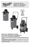
Owner’s Manual & Safety Instructions
Save This Manual Keep this manual for the safety warnings and precautions, assembly, operating,
inspection, maintenance and cleaning procedures. Write the product’s serial number in the back of the manual
near the assembly diagram (or month and year of purchase if product has no number). Keep this manual and
the receipt in a safe and dry place for future reference.
abrasive blaster
40 lb.
ITEM 68992
20 lb.
Visit our website at: http://www.harborfreight.com
Email our technical support at: [email protected]
ITEM 68994
When unpacking, make sure that the product is intact
and undamaged. If any parts are missing or broken,
please call 1-800-444-3353 as soon as possible.
Copyright© 2012 by Harbor Freight Tools®. All rights reserved.
No portion of this manual or any artwork contained herein may be reproduced in
any shape or form without the express written consent of Harbor Freight Tools.
Diagrams within this manual may not be drawn proportionally. Due to continuing
improvements, actual product may differ slightly from the product described herein.
Tools required for assembly and service may not be included.
Read this material before using this product.
Failure to do so can result in serious injury.
Save this manual.
Table of Contents
Safety.......................................................... 2
Maintenance............................................... 16
Specifications.............................................. 6
Parts Lists and Diagrams........................... 18
Setup........................................................... 7
Warranty..................................................... 20
Safety
Operation.................................................... 14
WARNING SYMBOLS AND DEFINITIONS
This is the safety alert symbol. It is used to alert you to potential personal injury hazards.
Obey all safety messages that follow this symbol to avoid possible injury or death.
Setup
Indicates a hazardous situation which, if not avoided,
will result in death or serious injury.
Indicates a hazardous situation which, if not avoided,
could result in death or serious injury.
Indicates a hazardous situation which, if not avoided,
could result in minor or moderate injury.
Addresses practices not related to personal injury.
Operation
IMPORTANT SAFETY INSTRUCTIONS
Instructions Pertaining to a Risk of Fire,
Electric Shock, or Injury to Persons
WARNING – When using tools, basic precautions should always be followed, including the following:
General
To reduce the risks of electric shock, fire, and injury to persons, read all the instructions before using the tool.
Maintenance
Work Area
1. Keep the work area clean and well lighted.
Cluttered benches and dark areas increase the
risks of electric shock, fire, and injury to persons.
3. Keep bystanders, children, and visitors away
while operating the tool. Distractions are able
to result in the loss of control of the tool.
2. Do not operate the tool in explosive atmospheres,
such as in the presence of flammable liquids,
gases, or dust. The tool is able to create sparks
resulting in the ignition of the dust or fumes.
Page 2
For technical questions, please call 1-800-444-3353.
Item 68992
68994
3. Avoid unintentional starting. Be sure the switch
is off before connecting to the air supply.
Do not carry the tool with your finger on the switch or
connect the tool to the air supply with the switch on.
5.
Use safety equipment.
A dust mask, non-skid safety shoes and
a hard hat must be used for the
applicable conditions.
6.
Always wear eye protection.
Wear ANSI-approved safety goggles.
7.
Always wear hearing protection
when using the tool.
Prolonged exposure to high intensity
noise is able to cause hearing loss.
8.
Wear heavy-duty work gloves during use.
Tool Use and Care
1. Use clamps or another practical way to secure
and support the workpiece to a stable platform.
Holding the work by hand or against the body is
unstable and is able to lead to loss of control.
2. Do not force the tool. Use the correct tool for the
application. The correct tool will do the job better
and safer at the rate for which the tool is designed.
3. Do not use the tool if the switch does not turn the
tool on or off. Any tool that cannot be controlled
with the switch is dangerous and must be repaired.
4. Disconnect the tool from the air source
before making any adjustments, changing
accessories, or storing the tool. Such preventive
safety measures reduce the risk of starting the
tool unintentionally. Turn off and detach the air
supply, safely discharge any residual air pressure,
and release the throttle and/or turn the switch to
its off position before leaving the work area.
Setup
2. Dress properly. Do not wear loose
clothing or jewelry. Contain long hair.
Keep hair, clothing, and gloves away from
moving parts. Loose clothes, jewelry, or long
hair increases the risk of injury to persons as
a result of being caught in moving parts.
4. Do not overreach.
Keep proper footing and balance at all times.
Proper footing and balance enables better
control of the tool in unexpected situations.
5. Store the tool when it is idle out of reach
of children and other untrained persons.
A tool is dangerous in the hands of untrained users.
6. Maintain the tool with care. Keep a cutting
tool sharp and clean. A properly maintained
tool, with sharp cutting edges reduces the
risk of binding and is easier to control.
7. Check for misalignment or binding of moving
parts, breakage of parts, and any other condition
that affects the tool's operation. If damaged,
have the tool serviced before using. Many accidents
are caused by poorly maintained tools.
There is a risk of bursting if the tool is damaged.
8. Use only accessories that are identified by the
manufacturer for the specific tool model. Use of
an accessory not intended for use with the specific
tool model, increases the risk of injury to persons.
Operation
1. Stay alert. Watch what you are doing and
use common sense when operating the tool.
Do not use the tool while tired or under the
influence of drugs, alcohol, or medication.
A moment of inattention while operating the
tool increases the risk of injury to persons.
Safety
Personal Safety
1. Tool service must be performed only
by qualified repair personnel.
2. When servicing a tool, use only identical
replacement parts. Use only authorized parts.
Item 68992
68994
3. Use only the lubricants supplied with the tool or
specified by the manufacturer.
Do not use any lubricants with this tool.
For technical questions, please call 1-800-444-3353.
Page 3
Maintenance
Service
Air Source
1.
Safety
Never connect to an air source that is
capable of exceeding 200 psi.
Over pressurizing the tool may cause
bursting, abnormal operation, breakage
of the tool or serious injury to persons.
Use only clean, dry, regulated compressed air at the
rated pressure or within the rated pressure range as
marked on the tool. Always verify prior to using the
tool that the air source has been adjusted to the rated
air pressure or within the rated air-pressure range.
2. Never use oxygen, carbon dioxide, combustible
gases or any bottled gas as an air source
for the tool. Such gases are capable of
explosion and serious injury to persons.
Save these instructions.
Symbols and Specific Safety Instructions
Setup
Symbol Definitions
Symbol
no
.../min
Property or statement
Symbol
Property or statement
No-load speed
NPT
National pipe thread, tapered
Revolutions or reciprocation per minute
NPS
National pipe thread, straight
Operation
PSI
Pounds per square inch of pressure
ft-lb
Foot-pounds of torque
BPM
Blows per minute
CFM
Cubic Feet per Minute flow
SCFM
Cubic Feet per Minute flow
at standard conditions
WARNING marking
concerning Risk of Eye Injury.
Wear ANSI‑approved eye protection.
WARNING marking concerning Risk of
Hearing Loss. Wear hearing protection.
WARNING marking concerning
Risk of Respiratory Injury. Wear
NIOSH‑approved dust mask/respirator.
WARNING marking concerning
Risk of Explosion.
Specific Safety Instructions
Maintenance
1. The warnings and precautions discussed in this
manual cannot cover all possible conditions and
situations that may occur. It must be understood
by the operator that common sense and caution
are factors which cannot be built into this
product, but must be supplied by the operator.
2. WARNING: This product, when used for abrasive
blasting and similar applications, produces chemicals
known to the State of California to cause cancer
and birth defects (or other reproductive harm).
(California Health & Safety Code § 25249.5, et seq.)
Page 4
WARNING: The brass components of
this product contain lead, a chemical
known to the State of California to cause
birth defects (or other reproductive harm).
(California Health & Safety code § 25249.5, et seq.)
3. Only use with accessories rated to handle the
forces exerted by this tool during operation.
Other accessories not designed for the forces
generated may break and forcefully launch pieces.
4. Attach all accessories properly to the tool before
connecting the air supply. A loose accessory
may detach or break during operation.
For technical questions, please call 1-800-444-3353.
Item 68992
68994
7. Use this tool with both hands only. Using tools
with only one hand can result in loss of control.
6. Install an in-line shutoff valve to allow
immediate control over the air supply in an
emergency, even if a hose is ruptured.
8. Do not lay the tool down until it has come to
a complete stop. Moving parts can grab the
surface and pull the tool out of your control.
Silicosis and Aluminum Oxide Warnings
1. Prohibit silica sand (or other substances
containing more than 1% crystalline silica)
as an abrasive blasting material and
substitute less hazardous materials.
2. Conduct air monitoring to measure worker exposures.
4. Practice good personal hygiene to avoid
unnecessary exposure to silica dust.
6. Use respiratory protection when source controls
cannot keep silica exposures below the NIOSH REL.
7. Provide periodic medical examinations for all
workers who may be exposed to crystalline silica.
8. Post signs to warn workers about the hazard and to
inform them about required protective equipment.
9. Provide workers with training that includes
information about health effects, work practices
and protective equipment for crystalline silica.
10. Report all cases of silicosis to State health
departments and to OSHA or the Mine Safety
and Health Administration (MSHA).
Vibration Precautions
This tool vibrates during use. Repeated or long-term
exposure to vibration may cause temporary or permanent
physical injury, particularly to the hands, arms and
shoulders. To reduce the risk of vibration-related injury:
1. Anyone using vibrating tools regularly or for an
extended period should first be examined by a
doctor and then have regular medical check-ups to
ensure medical problems are not being caused or
worsened from use. Pregnant women or people who
have impaired blood circulation to the hand, past
hand injuries, nervous system disorders, diabetes,
or Raynaud's Disease should not use this tool.
If you feel any symptoms related to vibration (such
as tingling, numbness, and white or blue fingers),
seek medical advice as soon as possible.
2. Do not smoke during use. Nicotine reduces
the blood supply to the hands and fingers,
increasing the risk of vibration-related injury.
3. Wear suitable gloves to reduce the
vibration effects on the user.
4. Use tools with the lowest vibration
when there is a choice.
5. Include vibration-free periods each day of work.
6. Grip tool as lightly as possible (while still keeping
safe control of it). Let the tool do the work.
7. To reduce vibration, maintain
tool as explained in this manual.
If abnormal vibration occurs, stop immediately.
Save these instructions.
Item 68992
68994
Setup
5. Wear washable or disposable protective clothes
at the work site. Shower and change into clean
clothes before leaving the work site to prevent
contamination of cars, homes and other work areas.
Operation
NIOSH recommends the following measures to
reduce crystalline silica exposures in the workplace
and prevent silicosis and silicosis-related deaths:
3. Use containment methods such as blast-cleaning
machines and cabinets to control the hazard
and protect adjacent workers from exposure.
For technical questions, please call 1-800-444-3353.
Page 5
Maintenance
WARNING! Abrasive blasting with sand containing
crystalline silica can cause serious or fatal respiratory
disease. Exposure to crystalline silica may cause
silicosis (a serious lung disease), cancer and death.
Exposure to aluminum oxide (a dust generated from
material removing processes) can result in eye, skin
and breathing irritation. Always use a NIOSH (National
Institute for Occupational Safety and Health) approved
respirator and safety goggles. Avoid skin exposure.
Proper ventilation in the work area is required. Read
and understand the 10 recommended measures below
to reduce crystalline silica exposures in the workplace
and prevent silicosis and silicosis related deaths.
Safety
5. Obey the manual for the air compressor
used to power this tool.
Functional Description
Specifications
Safety
Item
Air Pressure
68992
68994
60~125 PSI
Maximum Air Pressure
Air Inlet
125 PSI
1/4″ -18 NPT
Average Air Consumption
Required Air Hose
Abrasive Capacity
6~25 CFM
3/8″ or larger
40 lb.
20 lb.
Setup
Air Valve
Filler Cap
Filler Cap
Safety
Valve
Safety Valve
Air
Valve
Throttle
Valve
Throttle
Valve
Operation
Abrasive
Valve
Trigger Valve
Nozzle
Abrasive
Valve
Trigger Valve
Figure A: 68992 Components and Controls
Nozzle
Figure B: 68994 Components and Controls
Maintenance
Page 6
For technical questions, please call 1-800-444-3353.
Item 68992
68994
Initial Tool Set Up/Assembly
68992 Assembly Instructions
Note: Wrap 3 to 4 turns of thread seal tape on all airline connections. Make sure all joints are securely tightened.
Note: For additional information regarding the parts listed in this section,
refer to the 68992 Parts List and Diagram on page 18.
Pipe (13)
Intake
Manifold (14)
O-Ring (11)
Figure C
Hose
Connector
(20)
Tank (1)
Nipple
Connector (16)
Abrasive
Valve (18B)
assembly
Abrasive
Valve (18B)
Abrasive Outlet
Pipe (22)
1. Attach Abrasive Valve (18B) assembly’s Nipple
Connector (16) to bottom of Tank (1). Barbed fitting
of Abrasive Outlet Pipe (22) should face away
from Handle Bar brackets. See Figure C.
Figure D
Setup
Filler Cap (12)
Air Hose
(21)
2. Attach the end of the Pipe (13) to
Intake Manifold (14). See Figure D.
3. Thread the other end of the Pipe (13) into
the top of the Tank (1), as shown.
NOTE: When tightened, parts connected to the Pipe (13)
should have the orientation shown in Figure D.
4. Attach the male end of the Air Hose (21) to
the Abrasive Outlet Pipe (22) underneath
the Tank and tighten (not shown).
5. Attach female end of Air Hose (21) to
Hose Connector (20) of Gauge Assembly.
Operation
Tank (1)
Safety
Read the entire Important Safety Information section at the beginning of this
manual including all text under subheadings therein before set up or use of this product.
Maintenance
6. Put O-Ring (11) into Filler Cap (12).
Screw the Filler Cap (12) onto the fill
port of the Tank (1). See Figure D.
Item 68992
68994
For technical questions, please call 1-800-444-3353.
Page 7
Handle Grips (7)
Cotter Pin (3)
Axle (5)
Safety
Handlebars (6)
Bolts (8)
Cotter Pin (3)
Foot (4)
Nut (9)
Abrasive
Hose (24)
Wheel (2)
Figure E
7. Slide Handle Grips (7) onto the Handlebars (6).
See Figure E.
Setup
8. Attach Handle Bars to Tank using Bolts (8)
and Nuts (9). The Handle Bars must curve
back and the holes at the bottom must be
parallel to each other. See Figure E.
9. Slide open end of Abrasive Hose (24) onto Abrasive
Outlet Pipe (22). Secure in place using Clamp (23).
Figure F
10. Attach the Foot (4) to the Tank using
a Cotter Pin (3). See Figure F.
11. Attach one Wheel (2) to the Axle (5)
using a second Cotter Pin.
12. Slide the Axle through the holes in
the bottom of the Handlebars.
13. Attach the other Wheel to the Axle
using the remaining Cotter Pin.
Safety
Valve (10)
Operation
Tank (1)
Figure G
14. Thread the Safety Valve (10) into the
hole at the top of the Tank.
WARNING! To prevent serious injury and
death from explosion:
Do not thread anything other than the
Safety Valve (10) into the hole provided
at the top of the Tank (1).
Maintenance
15. After assembly, use a wrench to make sure
all threaded connections are tight.
Page 8
For technical questions, please call 1-800-444-3353.
Item 68992
68994
68994 Assembly Instructions
Note: Wrap 3 to 4 turns of thread seal tape on all airline connections. Make sure all joints are securely tightened.
Safety
Note: For additional information regarding the parts listed in this section,
refer to the 68994 Parts List and Diagram on page 19.
1. Place the Tank (1) on a table.
2
le
Tab
4
3
Figure H
5. Thread the Air Inlet assembly into the top
of the Tank as shown in Figure J.
6. Attach the Air Hose (13) to the Hose Connector (12).
2. Slide each Leg (4) onto a post as shown in
Figure H, and secure with a Cotter Pin (3).
Setup
Figure J
1
3. Thread the Safety Valve (2) into the
hole at the top of the Tank (1).
Operation
WARNING! To prevent serious injury and
death from explosion:
Do not thread anything other than the Safety Valve (2)
into the hole provided at the top of the Tank (1).
Figure K
4. Assemble the Air Inlet assembly (see Figure I):
a. Thread the Pipe (7) into the Air Valve (11).
b. Thread the Nipple Connector (9)
into the other side of the Air Valve (11).
7. Assemble one end of a Nipple Connector (9) into
the Abrasive Outlet Pipe (22), and the other end
into the Abrasive Valve (11B). See Figure K.
8. Thread another Nipple Connector (9) into
the other end of the Abrasive Valve (11B),
and then thread it into the Tank (1).
Maintenance
Figure I
c. Thread the other end of the Nipple Connector (9)
into the T-Connector (8).
d. Thread the Air Inlet (10) into the other
side of the T-Connector (8).
e. Thread another Nipple Connector (9) into
the bottom of the T-Connector (8).
f. Thread a Throttle Valve (11A) onto
that Nipple Connector (9).
g. Thread the Hose Connector (12)
into the Throttle Valve (11A).
Item 68994
68992
68994
For technical questions, please call 1-800-444-3353.
Page 9
Safety
15
Figure L
9. Assemble the Nozzle Assembly (see Figure L):
22
16
14
a. Thread the Nozzle Valve (11C)
onto the Adapter (16).
b. Thread a Nipple Connector (9) into the
other side of the Nozzle Valve (11C).
c. Onto the other end of the Nipple Connector (9),
add Nozzle Gasket (19) and a Nozzle (18A – 18D).
d. Thread the Nozzle Capnut (17)
on over the Nozzle.
14
Figure M
10. Attach the nozzle assembly to the
Abrasive Hose (15), using the Clamp (14)
to secure them together.
Setup
11. Use another Clamp (14) to attach the other
end of the Abrasive Hose (15) to the Abrasive
Outlet Pipe (22). See Figure M.
12. Connect the Air Hose (13) to the
Abrasive Outlet Pipe (22).
13. After assembly, use a wrench to make sure
all threaded connections are tight.
Operation
Maintenance
Page 10
For technical questions, please call 1-800-444-3353.
68994
Item 68992
68994
To prevent serious injury from explosion:
Use only clean, dry, regulated, compressed air to power this tool.
Do not use oxygen, carbon dioxide, combustible gases,
or any other bottled gas as a power source for this tool.
2. Attach an air hose to the compressor's air outlet.
Connect the air hose to the air inlet of the tool.
Other components, such as a coupler plug
and quick coupler, will make operation
more efficient, but are not required.
WARNING! To prevent serious injury
from accidental operation:
Do not install a female quick coupler on the tool.
Such a coupler contains an air valve that will
allow the air tool to retain pressure and operate
accidentally after the air supply is disconnected.
5. Turn on the air compressor according to
the manufacturer's directions and allow it
to build up pressure until it cycles off.
6. Adjust the air compressor's output regulator
so that the air output is enough to properly
power the tool, but the output will not exceed
the tool's maximum air pressure at any time.
Adjust the pressure gradually, while checking the
air output gauge to set the right pressure range.
7. Inspect the air connections for leaks.
Repair any leaks found.
8. If the tool will not be used at this time, turn off
and detach the air supply, safely discharge
any residual air pressure, and release
the throttle and/or turn the switch to its off
position to prevent accidental operation.
Note: Residual air pressure should not be present
after the tool is disconnected from the air supply.
However, it is a good safety measure to attempt to
discharge the tool in a safe fashion after disconnecting
to ensure that the tool is disconnected and not powered.
Maintenance
Note: Air flow, and therefore tool performance, can
be hindered by undersized air supply components.
The air hose must be long enough to reach
the work area with enough extra length to
allow free movement while working.
4. Close the in-line shutoff valve between
the compressor and the tool.
Setup
Note: An oiler system should not be used
with this tool. The oil will mix with the material
being propelled, causing poor results.
3. Turn the tool's throttle or switch to the off position;
refer to Operation section for description of controls.
Operation
1. Incorporate a filter, regulator with pressure gauge,
dryer, in-line shutoff valve, and quick coupler for
best service, as shown on Figure N on page 12
and Figure O on page 13. An in-line shutoff
ball valve is an important safety device because
it controls the air supply even if the air hose
is ruptured. The shutoff valve should be a
ball valve because it can be closed quickly.
Safety
Air Supply
Item 68992
68994
For technical questions, please call 1-800-444-3353.
Page 11
Description
Non-lubricated
Tools
A
Air Hose
Filter
Regulator
Lubricator (optional)
Coupler and Plug
Leader Hose (optional)
Air Cleaner / Dryer (optional)
Air Adjusting Valve (optional)
Maintenance
A
B
C
D
E
F
G
H
Operation
Lubricated
Tools
B
B
C
C
A
A
E
E
F
H
Connects air to tool
Prevents dirt and condensation from damaging tool or workpiece
Adjusts air pressure to tool
For air tool lubrication
Provides quick connection and release
Increases coupler life
Prevents water vapor from damaging workpiece
For fine tuning airflow at tool
G
D
Function
Setup
Figure N: Portable Air Supply Setup
Safety
Page 12
For technical questions, please call 1-800-444-3353.
Item 68992
68994
Item 68992
68994
For technical questions, please call 1-800-444-3353.
Page 13
A
B
C
D
E
F
G
H
I
J
K
L
M
N
O
F
Description
F
E
I
I
J
Operation
N
K
J
H
Setup
Function
H
L
L
M
O
Safety
For noise and vibration reduction
Secures air compressor in place
Isolates sections of system for maintenance
For vibration reduction
Distributes air to branch lines
To drain moisture from system
Brings air to point of use
Connects air to tool
Prevents dirt and condensation from damaging tool or workpiece
Adjusts air pressure to tool
For air tool lubrication
Provides quick connection and release
Increases coupler life
Prevents water vapor from damaging workpiece
For fine tuning airflow at tool
Non-lubricated
Tools
C
C
Vibration Pads
Anchor Bolts
Ball Valve
Isolation Hose
Main Air Line - 3/4″ minimum recommended
Ball Valve
Branch Air Line -1/2″ minimum recommended
Air Hose
Filter
Regulator
Lubricator (optional)
Coupler and Plug
Leader Hose (optional)
Air Cleaner / Dryer (optional)
Air Adjusting Valve (optional)
B
A
Maintenance
B
A
C D
G
Lubricated
Tools
Slope
Figure O: Stationary Air Supply Setup
F
Operating Instructions
Read the entire Important Safety Information section at the beginning of this
manual including all text under subheadings therein before set up or use of this product.
Safety
Inspect tool before use, looking for damaged, loose, and missing parts.
If any problems are found, do not use tool until repaired.
Tool Set Up
TO PREVENT SERIOUS INJURY FROM ACCIDENTAL OPERATION:
Close all Valves, detach the air supply, safely discharge any residual air pressure in the tool
(see After Blasting: on page 15), and close all Valves again before performing any procedure in this section.
To prevent serious injury:
Do not adjust or tamper with any control or component in a way not specifically explained within
this manual. Improper adjustment can result in tool failure or other serious hazards.
Setup
Abrasive Selection
The type of abrasive selected effects the time
required to blast clean a given surface area.
Particularly for large surfaces, test one or more of the
following abrasives to determine which is most effective:
a. Silicon Carbide
WARNING: Do not use sand or other blasting
materials that contain crystalline silica.
Note: Check to ensure the abrasives are dry
and clean so that they do not clog the unit.
Note: The Nozzle size depends on grit of media used.
The larger sizes are best suited to glass
beads and walnut shells, while smaller sizes
are best suited for fine aluminum oxide.
Change the nozzle as needed to suit the abrasive.
b. Aluminum Oxide
c. Glass Beads
d. Walnut Shells
Operation
Loading Abrasive
1. Wear protective gear including a
NIOSH-approved respirator.
2. Close the Air Valve, Abrasive Valve,
and Trigger Valve.
3. Remove Filler Cap.
4. Insert Funnel into Tank and pour in abrasive
(up to 3/4 full). Do not fill more than 3/4 of the Tank.
Note: If humidity in your region is 90% or more,
only fill the tank halfway and check the
Water Trap Filter (part 17 for item 68992,
sold separately for item 68994) more frequently.
5. Re-attach Filler Cap securely.
6. Turn on the compressor and set the regulator to the
pressure recommended for this Blaster (60~125 PSI).
CAUTION! Do not exceed 125 PSI.
Workpiece and Work Area Set Up
Maintenance
1. Designate a work area that is clean and well‑lit.
The work area must not allow access by children
or pets to prevent distraction and injury.
2. Route the air hose along a safe route to reach
the work area without creating a tripping hazard
or exposing the air hose to possible damage.
The air hose must be long enough to reach
the work area with enough extra length to
allow free movement while working.
Page 14
3. Secure loose workpieces using a vise or clamps
(not included) to prevent movement while working.
4. There must not be hazardous objects
(such as utility lines or foreign objects) nearby
that will present a hazard while working.
For technical questions, please call 1-800-444-3353.
Item 68992
68994
General Operating Instructions
2. Close all four Valves, then connect air supply.
3. Open Air Valve. Check for any air leaks at
the Filler Cap. Replace O-Ring if leaking.
4. Fully open the Abrasive Valve.
5. Point the Nozzle at the work so that the abrasive will
strike the surface of the work at about a 45° angle.
6. Grip the Discharge Hose firmly, and
QUICKLY open the Trigger Valve fully.
CAUTION: Do not attempt to regulate air/abrasive
mixture discharge rate with the Trigger Valve.
Doing so will ruin it.
To stop in the middle of operation,
QUICKLY close the Trigger Valve fully.
WARNING! Keep Nozzle pointed in a safe direction
until the blaster is completely shut down.
8. Close Air Valve, Abrasive Valve, and Throttle Valve.
9. Quickly open the Trigger Valve fully. Allow abrasive
and any compressed air to leave the Nozzle.
Safety
1. WARNING! Wear ANSI-approved safety goggles
and NIOSH-approved respirator under
blasting hood, and heavy-duty canvas gloves
when operating the Abrasive Blaster.
After Blasting:
10. Close Trigger Valve.
11. Close all Valves.
12. Pull out on ring on Safety Valve to make
sure tank is not pressurized.
13. To prevent accidents, detach the air supply, safely
discharge any residual air pressure in the tool,
and close all valves after use. Clean external
surfaces of the tool with clean, dry cloth.
Then store the tool indoors out of children's reach.
Setup
Note: Both Abrasive Valve and Trigger Valve should
be either fully opened or fully closed at all times.
7. Crack open slightly Throttle Valve to start
blasting. Regulate THIS valve handle
position for optimum blasting pressure.
Note: The flow rate of the abrasive may be irregular
when the unit is first started. Provided the abrasive is dry,
the flow rate will stabilize in approximately one minute.
Maintenance
Operation
Note: The impact pattern of the blast is affected by the
output pressure and the distance from the workpiece.
Item 68992
68994
For technical questions, please call 1-800-444-3353.
Page 15
User‑Maintenance Instructions
Procedures not specifically explained in this manual must
be performed only by a qualified technician.
Safety
TO PREVENT SERIOUS INJURY FROM ACCIDENTAL OPERATION:
Close all Valves, detach the air supply, safely discharge any residual air pressure in the tool
(see After Blasting: on page ), and close all Valves again before performing any procedure in this section.
To prevent serious injury from tool failure:
Do not use damaged equipment. If abnormal noise, vibration,
or leaking air occurs, have the problem corrected before further use.
Cleaning, Maintenance, and Lubrication
Note: These procedures are in addition to the regular checks and maintenance
explained as part of the regular operation of the air-operated tool.
Setup
1. BEFORE EACH USE, inspect the general
condition of the tool. Check for:
• loose hardware or housing,
• misalignment or binding of moving parts,
• cracked or broken parts, and
• any other condition that may
affect its safe operation.
Operation
2. Daily - Air Supply Maintenance:
Every day, maintain the air supply according
to the component manufacturers' instructions.
Drain the moisture filter regularly.
Performing routine air supply maintenance
will allow the tool to operate more safely
and will also reduce wear on the tool.
3. When re-using abrasive, sharp edges of abrasive
particles eventually become rounded and lose
cutting ability. At this point replace the abrasive.
4. The parts of the Blaster that require frequent wear
inspection and occasional replacement are those that
carry the air/abrasive mixture. Pay particular attention
to the Abrasive Hose, Gasket, the Abrasive Valve,
the Trigger Valve and the Nozzles, as they will wear
out much more quickly than the other pieces.
5. Abrasive Hose inspection:
When new, the Abrasive Hose has 1/4″ ID.
The Hose will need to be replaced when its side
walls develop leaks or show blisters on the surface.
WARNING! The hose could have residual abrasive or
suddenly burst. Point the nozzle in a safe direction
and wear all safety gear when doing this test.
a. Close the Abrasive and Trigger Valves.
b. Adjust the air pressure to 60~125 PSI.
c. For item 68992 only, open the Air Valve.
d. Open the Throttle Valve.
e. Then, run your fingers along the length of
the Hose. An enlarged spot (or bubble)
indicates a weakened section of the Hose.
Do not use the Blaster if this problem is
present - replace the entire Hose first.
6. To protect the compressor and its engine
or motor from damage by abrasive or dust
from Abrasive blasting, keep the compressor
up‑wind of the Blaster or in a separate room.
Maintenance
CAUTION! Air leaks in any of the above mentioned
parts need to be repaired before use.
Page 16
For technical questions, please call 1-800-444-3353.
Item 68992
68994
2. Poor or irregular flow of the abrasive may also
be due to low air pressure or a worn Nozzle.
To correct, increase the air pressure (to no more
than 125 PSI) and/or replace the worn Nozzle.
Operation
Setup
1. Excess moisture will cause the abrasive to slow
or stop flowing through the Abrasive Outlet Pipe.
To correct, check the abrasive by pouring a 6″
cone of abrasive on dry newspaper. After several
minutes, remove the abrasive from the newspaper.
Do not use the abrasive if the newspaper is moist.
Safety
Troubleshooting
The manufacturer and/or distributor has provided the parts list and assembly diagram
in this manual as a reference tool only. Neither the manufacturer or distributor
makes any representation or warranty of any kind to the buyer that he or she is
qualified to make any repairs to the product, or that he or she is qualified to replace
any parts of the product. In fact, the manufacturer and/or distributor expressly
states that all repairs and parts replacements should be undertaken by certified and
licensed technicians, and not by the buyer. The buyer assumes all risk and liability
arising out of his or her repairs to the original product or replacement parts
thereto, or arising out of his or her installation of replacement parts thereto.
Record Product's Serial Number Here:
Note: If product has no serial number, record month and year of purchase instead.
Note: Some parts are listed and shown for illustration purposes only,
and are not available individually as replacement parts.
Item 68992
68994
For technical questions, please call 1-800-444-3353.
Page 17
Maintenance
PLEASE READ THE FOLLOWING CAREFULLY
Parts Lists and Diagrams
68992 Parts List and Diagram
Safety
Part
1
2
3
4
5
6
7
8
9
10
11
12
Description
Tank
Wheel
Cotter Pin
Foot
Axle
Handlebar
Handle Grip
Bolt
Nut
Safety Valve
O-Ring
Filler Cap
Qty
1
2
3
1
1
2
2
4
4
1
1
1
Part
13
14
15
16
17
18
18-A
18-B
18-C
19
20
21
Description
Pipe
Intake Manifold
Pressure Gauge
Nipple Connector
Water Trap Filter
Air Supply Valve 3/8"
Throttle Valve 3/8"
Abrasive Valve 3/8"
Trigger Valve 3/8"
Air Inlet
Hose Connector
Air Hose
Qty
1
1
1
5
1
1
1
1
1
1
1
1
Part
22
23
24
25
26
27A
27B
27C
27D
28
29
30
Description
Abrasive Outlet Pipe
Clamp
Abrasive Hose
Adapter
Nozzle Gasket
3.6 mm Nozzle
3.2 mm Nozzle
2.7 mm Nozzle
2.4 mm Nozzle
Nozzle Capnut
Funnel
Blasting Hood
Qty
1
2
1
1
1
1
1
1
1
1
1
1
Setup
Operation
Maintenance
Page 18
For technical questions, please call 1-800-444-3353.
Item 68992
68994
68994 Parts List and Diagram
Description
Tank
Safety Valve
Cotter Pin
Leg
Filler Cap
O-Ring
Pipe
T-Connector
Nipple Connector
Air Inlet
Qty
1
1
3
3
1
1
1
1
5
1
Part
11
11A
11B
11C
12
13
14
15
16
17
Description
Air Valve 3/8"
Throttle Valve 3/8"
Abrasive Valve 3/8"
Trigger Valve 3/8"
Hose Connector
Air Hose
Clamp
Abrasive Hose
Adaptor
Nozzle Capnut
Qty
1
1
1
1
1
1
2
1
1
1
Part
18A
18B
18C
18D
19
20
21
22
Description
3.6 mm Nozzle
3.2 mm Nozzle
2.7 mm Nozzle
2.4 mm Nozzle
Nozzle Gasket
Funnel
Blasting Hood
Abrasive Outlet Pipe
Qty
1
1
1
1
1
1
1
1
Maintenance
Operation
Setup
1
2
3
4
5
6
7
8
9
10
Safety
Part
Item 68994
68992
68994
For technical questions, please call 1-800-444-3353.
Page 19
Limited 90 Day Warranty
Harbor Freight Tools Co. makes every effort to assure that its products meet high quality and durability standards,
and warrants to the original purchaser that this product is free from defects in materials and workmanship for the
period of 90 days from the date of purchase. This warranty does not apply to damage due directly or indirectly,
to misuse, abuse, negligence or accidents, repairs or alterations outside our facilities, criminal activity, improper
installation, normal wear and tear, or to lack of maintenance. We shall in no event be liable for death, injuries
to persons or property, or for incidental, contingent, special or consequential damages arising from the use of
our product. Some states do not allow the exclusion or limitation of incidental or consequential damages, so the
above limitation of exclusion may not apply to you. This warranty is expressly in lieu of all other
warranties, express or implied, including the warranties of merchantability and fitness.
To take advantage of this warranty, the product or part must be returned to us with transportation charges
prepaid. Proof of purchase date and an explanation of the complaint must accompany the merchandise.
If our inspection verifies the defect, we will either repair or replace the product at our election or we may
elect to refund the purchase price if we cannot readily and quickly provide you with a replacement. We will
return repaired products at our expense, but if we determine there is no defect, or that the defect resulted
from causes not within the scope of our warranty, then you must bear the cost of returning the product.
This warranty gives you specific legal rights and you may also have other rights which vary from state to state.
3491 Mission Oaks Blvd. • PO Box 6009 • Camarillo, CA 93011 • (800) 444-3353