1
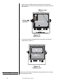
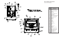
WI-130 WDAC
Service Manual
2
WI-130 WDAC Service Manual
Table of Contents
Introduction ........................................................................................................... 5
About This Manual ..................................................................................... 5
Front Panel Keys and Functions .......................................................................... 5
Hard Keys .................................................................................................. 6
Soft Keys ................................................................................................... 7
Wall Mounting Instructions ................................................................................... 7
Accessing Setup ................................................................................................... 8
User Level ................................................................................................. 9
User-Select Level ........................................................................ 10
User-Set Level ............................................................................. 11
User-View Level ........................................................................... 12
Configure Level ....................................................................................... 13
Configure-Menu1 Level ............................................................... 14
Configure-Menu2 Level ............................................................... 18
Configure-Menu3 Level ............................................................... 20
Configure-Menu4 Level ............................................................... 21
Calibrate Level ......................................................................................... 25
Disassembly ....................................................................................................... 27
Re-assembly ...................................................................................................... 28
Appendix 1: Display Samples............................................................................. 29
Appendix 2: Tips on Using Harmonizer ............................................................. 32
Enclosure, Parts and Assy ................................................................................. 33
System Block Diagram ....................................................................................... 34
AC and AC/DC Power Supply Boards ............................................................... 35
Main Board ......................................................................................................... 36
Front Panel Overlay & Schematic ...................................................................... 37
Multi-Scale Board (Optional) & Multi-Scale J-Box ............................................. 38
External Cutoff Expansion Board ....................................................................... 39
Quartzell Board (Optional) & Memory Board ..................................................... 40
Enclosure w/Stand Outline Dwg ......................................................................... 41
Enclosure Panel Mount Outline Dwg ................................................................. 42
Option Board Connections ................................................................................. 43
Enclosure SSCU-8 Parts & Assy ....................................................................... 44
OPTO-22 Control Interface Device Specifications ............................................. 45
Wiring Diagrams for Input and Output Modules ................................................ 46
Remote Expanded Control I/O Board ................................................................ 47
Remote Keyboard Option ................................................................................... 48
WDAC to Keyboard Cable Connections ............................................................ 49
Keyboard Outline Dwg ....................................................................................... 50
Keyboard Panel Mtg. Detail ............................................................................... 51
I/O Cable Identification and Pin-Outs ................................................................. 52
Pages are numbered consecutively beginning with the cover page.
WI-130 WDAC Service Manual
3
Specifications
Power Input
Excitation
Operational Keys
Operational Annunciators
Display
Display rate
A to D Conversion Rate
Unit of Measure
Capacity Selections
Incremental Selections
Decimal locations
Displayed Resolution
Audio Output
Time and Date
Internal Resolution
115 Volts AC, 500 mA 50/60 Hz single phase
230 Volts AC, 250 mA, 50/60 Hz single phase
Optional 10-32 volts DC and AC noted above
10 Volts DC or 10 volts AC square wave capable of driving up to twenty 350-ohm weight
sensors or 1 QuartzellTM transducer
Zero, Tare, Print, Units, Select, Enter, Escape, Clear, 0-9,
Decimal Point and Five Soft Keys labeled per selected operational routine. All keys provide
users with tactile and audio acknowledgment when they are activated.
Displayed symbols indicate motion, center of zero, unit of measure and more.
1" H x 4.3" W vacuum fluorescent dot graphic display (32 X 128 dot layout)
Selectable, 0.1 to maximum readable updates
60 times per second
Pounds, kilograms, grams, ounces, pounds and ounces and two selectable custom units
Up to 10,000,000 selectable
Multiples and sub multiples of 1, 2, 5
88888888 pick any location relative to division size
Up to 1 part in 10,000,000
Audio tone for key contact assurance or operational alarms
Battery protected real time clock is standard
1,000,000 counts analog, QuartzellTM transducer higher
Harmonizer™ digital filtering:
Fully programmable to ignore noise and vibration
Standard input and outputs:
Four communications choices:
Com 1: RS232, RS-485/422
Com 2: RS232, 20 mA current loop
(One bi-directional signal per port)
Two set point I/O ports via OPTO 22 I/O modules
Available Options
Operating Temperatures
Enclosure
Dimensions
Weight
4
- Multi scale inputs
- DC operation at 10 to 32 VDC, 3.5 Amp
- OPTO 22 I/O Modules
- Remote Expanded Control Interface for 8, 16, 24, or 32 OPTO 22 I/O Modules
- Alpha-numeric, PC style keyboard
- Quartzell transducer interface
- Analog interface
14 to 104° F (-10 to 40° C), 10 to 90% relative humidity
Stainless steel wash down enclosure
12 3/8" H x 10 3/4" W x 5 1/4" D (31.43 cm x 27.31 cm x 13.34 cm)
17.5 lb, 7.8 kg
Agencies
NIST Class III/IIIL Certified COC# 95-008
Canadian Weights and Measures AM-5054
UL (115 VAC)
CUL (115 VAC)
FCC Class A
Warranty
2 year
WI-130 WDAC Service Manual
Introduction
About This Manual
This manual covers the information you need to configure and service your
WI-130 Weight Data Acquisition Controller (WDAC).
Major sections of this manual are headed by titles in a black bar like Introduction above. Subheadings appear in the left column. Instructions and
text appear on the right side of the page. Occasionally notes, tips, and
special instructions appear in the left column.
Front Panel Keys and Functions
The front panel is shown in Figure 1.
123456
SERIAL NO.
C A P A C I T Y : 0 0 0 0 0 x . 0 L B
Plug the WI-130 into an easily
accessible grounded outlet
only. Never use the unit without
an appropriate earthground
connection.
SELECT
0 0 0 0 x . 0 0 K G
PRINT
TARE
7
8
9
4
5
6
1
2
3
CLEAR
0
.
UNITS
C L A S S I I I / I I I L
ZERO
0
ENTER
ESCAPE
Figure 1
WI-130 Front Panel
WI-130 WDAC Service Manual
5
The keys on the front panel of the WI-130 are of two types, hard keys and
soft keys. Hard keys are labeled directly and soft key labels appear on the
display. Soft keys function differently at different times so their labels
change as needed.
Hard Keys
Below are brief descriptions for each of the hard key functions:
SELECT
UNITS
PRINT
6
Repeatedly press the SELECT key to scroll through the
available weight reading displays. (Examples - gross,
net, tare, minimum, maximum, etc.)
Press the UNITS key to scroll through the available units
of measure
Press the PRINT key to send data to a connected printer.
TARE
Press the TARE key to enter a tare weight, then press
SELECT to see the net display mode.
ZERO
0
Press the ZERO key to establish a zero reference. A
center-of-zero icon will be displayed. During motion an M
will appear below the center-of-zero icon.
ESCAPE
Press the ESCAPE key to back out of menus or cancel a
numeric entry without accepting the value.
CLEAR
Press the CLEAR to clear values from the display.
ENTER
Press the ENTER key to enter a keyed in value or accept
a displayed choice.
WI-130 WDAC Service Manual
Soft Keys
7
8
9
4
5
6
1
2
3
0
.
The numeric keypad is for
entering numbers.
Soft keys are so-called because their function is not fixed. Function can
change as the mode of operation changes or as the program for your
particular setup changes.
Their are five soft keys located directly below the display. If the keys are
needed during any operation, a label for each active key appears in the
display directly above. There are only five key labels available at one time
but this does not limit the potential usefulness of these keys. Programs can
be created to enable one key to access another level of operation with five
more key names and functions.
Wall Mounting Instructions
To mount the WI-130 to a wall, use 5/16" steel bolts through the four 11/32"
wide key hole slots in the mounting bracket. See WI-130 WDAC Enclosure
w/stand outline drawing in the back of this manual.
For mounting onto sheet metal use bolts, lock washers and nuts. The
minimum recommended material thickness is 16 gauge (0.059") steel or
0.080" aluminum. For bolting into threaded hole in metal, a 1/4" minimum
thread length is recommended.
For fastening to wood, use 5/16" diameter lag bolts with 3/4" minimum
engagement into the wood.
Directly mounting to sheetrock or plaster without reinforcement is not
recommended.
WI-130 WDAC Service Manual
7
Accessing Setup
There are three levels of WI-130 setup you can access through the front
panel:
User level
The first level is the User level. These are the most commonly
changed values and parameters that you will use in the course of
operating the WI-130.
Configuration level
The second level is the Configuration level. These items deal with
some of the basic functions of the WI-130 and do not need to be
accessed very often.
Calibration level
The third level is the Calibration level. This section will need to be
accessed only when the scale is being calibrated, or if you change
scale capacity or division size.
A different password is needed to access each level. Once you access the
level you want, the display presents a series of soft key choices. By pressing the appropriate soft key and following text prompts on the display, you
can set up your WI-130 to suit your needs.
You must key in the password
within 5 seconds of accessing
the password screen or the WI130 returns to normal operation.
IMPORTANT NOTE
The WI-130 can be sealed for
legal for trade use and the
software protected from
change by a hardware connection on the main board. If P19
is jumpered, the system is
sealed and programs cannot
be downloaded or altered. If
P19 is not jumpered the
system is not sealed and
programs can be downloaded
from the SimPoser software. A
jumper on P19 does not affect
the USER level. This level can
be accessed and changed no
matter what the condition of
P19.
8
Following are the instructions you need to access the setup of the WI-130.
1. Press and hold the ESCAPE key
until the WI-130 beeps. . .
The display asks for a password and
looks like Figure 2.
Figure 2
Password display
Below are the passwords and details for the three setup levels.
WI-130 WDAC Service Manual
User level
The default User password is 111.
Key in 111 and press ENTER. . .
the screen in Figure 3 is displayed.
The User level is not affected
by the condition of P19 on the
main board.
Figure 3
User level soft key group
Figure 4 is a flowchart showing what soft keys or choices appear as you
press the soft keys shown in Figure 3.
The values under SELECT in
the flowchart to the right are
not saved after a power down
and power up.
Figure 4
Soft key flowchart for User level
USER-CLOCK Level
Press the CLOCK soft key to access the time and date setting function.
1. The display shows the current
hour value. If this is not correct
key in a new value and press
ENTER or press ENTER to
accept the current value. . .
2. Repeat step 1 for minutes,
seconds, year, month, day, and
day of the week (0=Sunday,
1=Monday, etc.). . .
WI-130 WDAC Service Manual
The display shows the minutes
value.
Display returns to display shown in
Figure 3.
9
Press the SELECT soft key to access the USER-SELECT soft key group:
USER-SELECT Level
While in the this level the
display will show USERSELECT in the top left to
remind you of where you are in
the USER level.
• DISP
• SCALE
• TARE
• UNIT
• EXIT
Press this key to set the current display mode.
Press this key to select the scale number you want to use.
Press this key to enter a known tare weight.
Press this key to select the active units of measure.
Press this key to go back to the previous soft key set.
Following is a detailed description of the four functions listed above.
DISP (Display Mode)
The display mode you pick
may not be the one that
appears on the display. A
display mode called out in the
WT BASIC program overrides
the setting you make through
the front panel.
If you press the DISP soft key, follow these instructions:
1. The display shows the current
display mode number. Press
ENTER to accept this value or
key in a new number from the list
in Appendix 1, then press
ENTER to accept it.
2. Choose one of the following
active display values by keying in
0-13, then press ENTER. . .
Variable (#11) is a variable
value called out in a WT-BASIC
program. ADC (#13) stands for
Analog to Digital Counts.
SCALE
You cannot select a scale
number unless it has been
activated in the SimPoser
program and downloaded to
the WI-130.
0 = Gross
1 = Net
2 = Tare
3 = Min
4 = Max
5 = Rate of Change
6 = Gross Total
7 = Net Total
The display asks for the ACTIVE
VALUE. This is the active display
value.
The display returns to the USERSELECT screen.
8 = Count Total
9 = Trans. Total
10=Count
11=Variable
12=Piece Weight
13=ADC
If you press the SCALE soft key the display will ask you to select a scale
number. The currently active scale number is displayed. You can simply
type a new scale number and press the ENTER key. If you have multiple
scales attached to the indicator, this function chooses which scale's weight
is displayed and which one the ZERO and TARE keys will affect.
TARE
If you press the TARE soft key the display will show the current tare value
for the active scale. You may key in a new tare weight and press the ENTER
key to override the previous tare weight.
UNIT
If you press the UNIT soft key the display will ask you to key in a number (06) which represents the value you want to be active. Below are the seven
units to choose from and the corresponding number you need to key in for
this function:
0- lb
1- kg
2- g
3- oz
4- lb oz
5- custom 1
6- custom 2
Press the EXIT soft key to return to the USER level soft key group.
10
WI-130 WDAC Service Manual
Press the SET soft key to access the USER-SET soft key group shown
below:
USER-SET Level
• GRAPH
• PEAKS
• ACCUM
• PCWT
• EXIT
Press this key to set the parameters for bar graph and
checkweighing functions.
Press this key to reset the Min/Max.
Press this key to set the accumulator totals.
Press this key to set the pieceweight for counting functions.
Press this key to go back to the previous soft key set.
Following is a detailed description of the four functions listed above.
GRAPH
If you press the GRAPH soft key, follow these instructions:
1. The current MIN setting is
displayed. Press ENTER to
accept this value or key in a new
value and press ENTER. . .
2. Repeat step one, accept or
change the value, for UNDER,
OVER, MAX, and BASIS values.
BASIS is same as the active
values (0-13) shown below.
Variable (#11) is a variable
value called out in a WTBASIC program. ADC (#13)
stands for Analog to Digital
Counts.
PEAKS
ACCUM
0 = Gross
1 = Net
2 = Tare
3 = Min
4 = Max
5 = Rate of Change
6 = Gross Total
7 = Net Total
These values now apply when using
the bar graph or checkweighing
display.
8 = Count Total
9 = Trans. Total
10=Count
11=Variable
12=Piece Weight
13=ADC
If you press the PEAKS soft key the display asks if you want to reset the
MIN and MAX values now in memory. You are given the choice of YES or
NO. After choosing the display returns to the USER-SET level display.
If you press the ACCUM soft key, follow these instructions:
1. The display shows you the
current GROSS TOTAL in the
accumulator. You can change
this by keying in a new number
and pressing ENTER or press
ENTER to move to the next
ACCUM value. . .
2. Repeat step 1 for NET TOTAL,
COUNT TOTAL, and
TRANS(action) TOTAL. . .
PCWT
The UNDER value is displayed.
The display shows the NET TOTAL
value.
The display returns to the USERSET screen.
If you press the PCWT soft key the display shows the current value for the
piece weight. Accept this by pressing the ENTER key or key in a new piece
weight and press ENTER.
Press the EXIT key to return to the USER level soft key group.
WI-130 WDAC Service Manual
11
Press the VIEW soft key to access the USER-VIEW soft key group:
USER-VIEW Level
• VERS
Press this key to see WI-130 firmware revision date and
time. Serial number is currently not used. Configuration
information is displayed if a program has been downloaded
from SimPoser software.
• CAL
Press this key to view the state of jumper P19(Sealed/
Unsealed).
• VARS
Press this key to view the BASIC variables.
• STORES Press this key to view the numeric and string values used
with store and recall.
• EXIT
Press this key to go back to the previous soft key set.
Following is a detailed description of the four functions listed above.
VERS
If you press the VERS soft key you will see the firmware version number.
Serial number is currently not used. When you press any key, if you have
never downloaded a file from SimPoser, you will see only the word CONFIGURATION and no other information. If you have downloaded a file, the
following information is displayed:
License # of the SimPoser software.
Name of license holder.
Version number of the SimPoser software.
Name of the downloaded file (application program).
Time and date of the last download.
Press any key again and the USER-VIEW level is displayed.
CAL
Press the CAL soft key to see the current state of jumper P19. The display
will show Sealed or Unsealed.
VARS
If you press the VARS soft key you will be able to scroll through the variables you have in your basic program. Press the FIRST soft key to see the
first one and the NEXT soft key to scroll to the next one. Repeat this until
you are through and press the EXIT soft key to return to the USER-VIEW
level.
If no variables are defined the screen will show NO VARIABLES DEFINED.
STORES
If you press the STORES soft key, follow these instructions:
1. The display asks if you want to
DISPLAY NUMERICS?, and
gives you the choice of YES or
NO. If you press YES the display
will look like this:
12
WI-130 WDAC Service Manual
There are three types of
memory:
• Standard
• Expanded
• Memory Card
Standard memory has locations
0-1023 for numeric storage and
0-511 for string storage.
Expanded memory has locations
1024-8191 for numeric storage
and 512-4095 for string storage.
The memory card has locations
8192-73727 for numeric
storage and 4096-36863 for
string storage.
If you do not have the memory
installed, the location returns a
zero.
2. Press PREV (previous) to see
the previous numeric record.
Press NEXT to see the next
numeric record. Press SELECT
and the display will let you enter
a specific numeric record
number. When you press
ENTER that record number will
be displayed.
3. If you press NO in step one the
following screen is displayed.
4. This screen lets you view all the
strings stored in your BASIC
program. View them the same
way you did the numeric values.
5. Press EXIT to return to the
USER-VIEW level.
Press EXIT to return to the USER level. Press EXIT one more time and you
are back to normal operation. You have now seen all the parts of the USER
level. The next section of the manual covers front panel configuration.
Configure level
You must key in the password
within 5 seconds of accessing
the password screen or the WI130 returns to normal operation.
When your changes are
completed, secure and protect
them by placing a jumper on
P19!
The deafult password for the Configure level is 2045.
1. Press and hold the ESCAPE key
for 3-5 seconds. You will hear a 2nd
beep and the display will change.
Key in 2045 and press ENTER. . . the screen in Figure 5 is displayed.
Figure 5
Configuration level display
WI-130 WDAC Service Manual
13
Figure 6 is a flowchart showing what soft keys or choices appear as you
press the soft keys shown in Figure 5.
Under Misc. (print format) in
the flowchart to the right, the
default print format 0 shows
gross, tare and net weights. If
you choose another print
format (1-16) you need to
define the format in SimPoser
and download it to the WI-130.
(Select from
Appendix 1)
Figure 6
Soft key flowchart for Configure level
CONFIGURE-MENU 1 Level
Press the MENU1 soft key to access the following soft key group:
• SCALE
• UNITS
• SETPT
• SERIAL
When your changes are
completed, secure and protect
them by placing a jumper on
P19!
• EXIT
Press this key to set display update rate, zero range, print
return to zero, and accumulate return to zero.
Use this key to enable/disable units of measure.
Use this key to show setpoints, if used.
Use this key to set port #, baud rate, parity, databits, handshake, mode, and EOM character.
Press this key to go back to the previous soft key set.
Following are detailed instructions for setting these parameters.
If you press the SCALE soft key, follow these instructions:
14
WI-130 WDAC Service Manual
SCALE
Any value for display update
rate greater than 2 will be
considered as the maximum
update rate or 99.
1. The display will show the current
display rate (.1, .25, .5, 1, 2, 99)
times per second. Accept this by
pressing the ENTER key or key
in a new value and press the
ENTER key. . .
99 is five times per second.
2. Repeat step one for zero range
(0-100% allowed). Press ENTER
to accept this or key in a new
value and press ENTER . .
By default, when the PRINT
key is pressed, a print operation and an accumulation take
place. If you do not want the
accumulation to occur, a WTBASIC program assigning only
the DO PRINT command to the
PRINT key needs to be downloaded to the WI-130. A WTBASIC program can also
define an ACCUM. soft key
and assign accumulation to
that key only.
3. Repeat step one for print return
to zero (0-100% of cap.
allowed). Press ENTER
to accept this or key in a new
value and press ENTER . .
4. Repeat step one for accumulate
return to zero (0-100%
allowed). Press ENTER
to accept this or key in a new
value and press ENTER . . .
UNITS
Custom unit names must be
defined by SimPoser software
program.
The display shows the zero range
value. If a non-valid number is keyed
in the value will default to 99, which
is 5 times per second.
This is the percentage of capacity
that you are allowed to zero using
the ZERO hard key.
If you press the PRINT key, the
weight must be above this percentage of scale capacity and stable
before the operation will be allowed.
To perform this operation again, the
weight must first return to ZERO, be
stable, then exceed this percentage
of scale capacity, then another print
operation will be allowed.
If you perform an accumulation, the
weight must be above this percentage of scale capacity and stable
before the operation will be allowed.
To perform this operation again the
weight must first return to ZERO be
stable, then exceed this percentage
of scale capacity, then another print
or accumulation operation will be
allowed.
If you press the UNITS soft key, follow these instructions:
1. The display asks if you want to
enable the LB unit of measure
and shows you the current state
(ON or OFF). If the condition is
as you want it, simply press the
ENTER key. If you want to
WI-130 WDAC Service Manual
15
The custom conversion factor
is the number to be multipied
by the weight (in calibration
units) to get the desired
custom unit. Example: 1 lb = 5
inches of a certain steel rod.
Custom unit is inches. Calibration unit is lb. Conversion factor
is 5. With six lbs of weight on
the scale, 30 inches would be
displayed.
(Six lbs x 5 = 30 inches of
steel)
SETPT
Setpoint operations must be
defined by the SimPoser
software program.
SERIAL
change the condition, press the
YES or NO soft key, then the
ENTER key to move to the next
unit of measure. . .
2. Repeat step 1 for kilograms,
grams, ounces, pounds &
ounces, and custom units 1 and
2. The display asks for the
conversion factor for each
custom unit. Key in a value and
press ENTER. . .
The display returns to the
CONFIGURE-MENU1 display.
If you press the SETPT soft key the display asks you SHOW SETPOINTS?
What this means is, if you say yes, the display will show when setpoints turn
on and off by lighting small dots in the upper right corner. Press the YES soft
key if you want to see these dots, and press NO if you do not.
If you press the SERIAL soft key, follow these instructions:
1. The display prompts you for
serial port # to configure. Press
ENTER if displayed port is OK or
key in a new port number and
press ENTER. . .
2. Press ENTER to accept the baud
rate or key in a new baud rate
code number from the table
below and press ENTER. . .
Baud Rate Codes
0 = 300
4 = 9600
1 = 1200
5 = 19,200
2 = 2400
6 = 38,400
3 = 4800
7 = 56,700
16
The kilogram unit of measure is the
next one shown.
WI-130 WDAC Service Manual
The baud rate code number is
displayed.
The parity code number is displayed.
3. Press ENTER to accept the
parity or key in a new parity
code number from the table
below and press ENTER. . .
Parity Codes
0 = NONE
3 = SET
1 = ODD
4 = CLEAR
2 = EVEN
Setting this parameter to SET
will simulate 2 stop bits and no
parity detection.
This lets you choose parity as
even, odd, clear (logic 0 or
space), or set (logic 1 or mark).
Set (Mark)
Clear (Space)
Mark
Space
Odd
Even
The databits setting is displayed.
Data Bits
Stop Bits
Parity
7
8
7
8
7
7
2
1
2
1
1 or 2
1 or 2
none
none
none
none
odd
even
4. Press ENTER to accept the
databits setting or key in the new
databits value (7 or 8) and press
ENTER. . .
CTS is a hardware handshake
(ready/busy) which requires
two extra wires in your cable.
Xon/Xoff is a software handshake requiring no additional
hardware.
5. Press ENTER to accept the
handshake protocol setting or
key in a new code number for
the handshake from the table
below and press ENTER. . .
The mode code number is displayed.
Handshake Protocol Codes
0 = NONE
2 = Xon / Xoff
1 = CTS
3 = BOTH
6. Press ENTER to accept the
mode setting or key in a new
code number from the table
below and press ENTER. . .
Enquire Mode must be enabled
and the EOM character MUST
be set to 5 to operate with Truck
Weigh Software program.
The handshake protocol code
number is displayed.
The EOM (end of message) value is
displayed.
Serial Mode Control Codes
0 = BASIC control
2 = Disabled
1 = Keyboard
3 = Multidrop
6 = Enquire
WI-130 WDAC Service Manual
17
BASIC Control - Control of the serial port is through the BASIC program
executing in the WI-130.
Keyboard Control of the serial port is through an attached keyboard.
Disabled The serial port is not in use for this configuration.
Multidrop The serial port is configured in RS-485 Multidrop mode.
EOM ASCII code #13 is
carriage return.
7. Press ENTER to accept the
EOM character or key in a new
number from 0-256 and press
ENTER. . .
The display returns to the
CONFIGURE-MENU1 display.
This completes the instructions for all the parameters of Menu 1.
CONFIGURE-MENU 2 Level
Press the MENU2 soft key to access the following soft key group:
• MOTION
Use this key to set the motion detection window size in
divisions and the time window in seconds.
For example: If you set divisions to 3 and seconds to 1, if
the weight value does not change more than 3 divisions
in one second, the scale or weight is considered stable.
In the SimPoser software the
Harmonizer constant choices
are 0 through 10. This setting
is to be made in the "real
world" on a working system so
there are more levels available
from the front panel.
• AZT
Use this key to enable AZT. If you enable AZT you can
set the division size and seconds. The division size you
pick defines a range above and below zero. When scale
weight is inside this range for the number of seconds you
picked, ½ of the weight will be zeroed. The indicator will
repeat removing ½ the weight every X seconds. X being
the number of seconds you have picked.
•FILTER
Use this key to set up the Harmonizer filtering. A full
explanation is given below. See Appendix 2 for tips on
using Harmonizer.
The A-D weight conversion happens 60 times per second
in the WI-130. AVG is the number of conversions you
want to average. For example, if you pick 30, the unit will
average the weight values from the last 30 conversions
or ½ second and uses that value for displayed data.
The next choice you have is for turning the Harmonizer
filtering on or off. If you turn the Harmonizer filtering on
you need to set the Harmonizer Constant. Typical values
are between 1-10. Set the number low for small vibration
problems and higher for more dampening effect.
The purpose of the Harmonizer Threshold is so the
indicator will respond quickly to large weight changes.
Harmonizer Threshold is the amount of weight swings, in
calibration units, beyond which the Harmonizer will be
temporarily disabled. For example, if you set this to 10
lbs, a weight swing over 10 pounds occuring during the
sample time (30 A-D conversions in our example) will
disable the Harmonizer until the weight swing during the
sample time drops below 10 lbs.
18
WI-130 WDAC Service Manual
• TMOUT
Use this key to set Zero Timeout, Tare Timeout, Print
Timeout and Accumulate Timeout. This is the amount of
time the WI-130 will wait for motion to cease and perform
the function after the key is pressed.
For example, if Zero Timeout is set to 3 seconds, when
the ZERO key is pressed the unit will zero the scale if
there is no motion. If there is motion and motion ceases
within 3 seconds the unit will zero the scale. If motion
doesn't cease the key press is ignored.
• EXIT
Press this key to go back to the previous soft key set.
Following are detailed instructions for setting these parameters.
MOT'N (motion)
If you press the MOT'N soft key, follow these instructions:
1. The current value for the motion
window size, in divisions, is
shown. Press ENTER to accept
this value or key in a new value
and press ENTER. . .
2. Press ENTER to accept this time
period or key in a new value and
press ENTER. . .
AZT (auto zero tracking)
The display returns to the
CONFIGURE-MENU2 display.
If you press the AZT soft key, follow these instructions:
1. The current value for the AZT
window size, in divisions, is
shown. Press ENTER to accept
this value or key in a new value
and press ENTER. . .
2. Press ENTER to accept this time
period or key in a new value and
press ENTER. . .
FILTER
The current time window in seconds
is displayed.
The current time window in seconds
for AZT is displayed.
The display returns to the
CONFIGURE-MENU2 display.
If you press the FILTER soft key, follow these instructions:
1. The display shows the current
value for the number of samples
to average. Press ENTER to
accept this value or key in a new
value and press ENTER. . .
WI-130 WDAC Service Manual
The display shows the state of the
Harmonizer filtering( ON or OFF).
19
When your changes are
completed, secure and protect
them by placing a jumper on
P19!
2. Press YES to enable Harmonizer
or NO to disable the Harmonizer
parameter, then press ENTER . . . The current Harmonizer Constant
value is displayed.
3. Press ENTER to accept this
value or key in a new value and
press ENTER. . .
4. Press ENTER to accept this
value or key in a new value and
press ENTER. . .
TMOUT (timeout)
The current Harmonizer Threshold
value is displayed. This value is in
calibration units.
The display returns to the
CONFIGURE-MENU2 display.
If you press the TMOUT soft key, follow these instructions:
1. The current value for Accumulate
Timeout is displayed. Press
ENTER to accept this value or
key in a new value and press
ENTER.
2. Repeat step 1 for Print Timeout,
Zero Timeout, and Tare
Timeout. . .
The display returns to the
CONFIGURE-MENU2 display.
Press the EXIT soft key to return to the CONFIGURE display.
CONFIGURE- MENU 3 Level
Press the MENU3 soft key to access the following soft key group:
• KEYS
• VALS
• DMODE
• EXIT
Press this key to enable or disable front panel keys.
Press this key to enable or disable the display values
(gross, net, min., max., ect.)
Press this key to pick a power-up display mode from the
over 35 available. See Appendix 1: Display Samples.
Press this key to go back to the previous soft key set.
Following are detailed instructions for setting these parameters.
KEYS
If you press the KEYS soft key, follow these instructions:
1. The current setting (enabled ON
or OFF) for the SELECT hard
key is displayed. Press YES to
enable the key or NO to disable
the key, then press ENTER . .
20
WI-130 WDAC Service Manual
The current setting for the UNITS
hard key is displayed.
2. Repeat step 1 for UNITS,
PRINT, TARE, ZERO,
AUTOTARE, and KEYPAD
TARE. . .
VALS
If you press the VALS soft key, follow these instructions.
1. The current setting (enabled ON
or OFF) for the GROSS display
value is displayed. Press YES to
enable the active value or NO to
disable this active display value,
then press ENTER . .
2. Repeat step 1 for all the display
values (NET, TARE, MIN., MAX.,
ROC, G-TOT, N-TOT, C-TOT,
#-TOT, COUNT, VARIABLE,
PCWT, and ADC. . .
DMODE
The display returns to the
CONFIGURE-MENU3 display.
The current setting for the NET
active value is displayed.
The display returns to the
CONFIGURE-MENU3 display.
If you press the DMODE soft key, press ENTER to accept the display mode
number shown or key in a new number (see Appendix 1) and press ENTER.
The display returns to the CONFIGURE-MENU3 display. Press the EXIT key
to return to the CONFIGURE display.
CONFIGURE-MENU 4
Level
Press the MENU4 soft key to access the CONFIGURE-MENU 4 soft key
set:
• FMTPT
Press this key and enter the serial port # you want each of
16 print formats to be printed through.
• ANOUT
Press this key to select the Minimum, Maximum and Basis
parameters used with the optional Analog Output card.
Minimum Value
The Minimum Value is the lowest value that will be represented by the Analog Output.
Maximum Value
The Maximum Value is the highest value that will be represented by the Analog Output.
Selection Basis
Selection basis is the active display value upon which the
output of the analog output will be based.
When your changes are
completed, secure and protect
them by placing a jumper on
P19!
Span Adjust
Allows you to adjust the highest value of the analog output.
Offset Adjust
Allows you to adjust the lowest value of the analog output.
WI-130 WDAC Service Manual
21
• ROC
ROC stands for Rate of Change. Press this key to set up
your WI-130 Indicator to calculate Rate of Change for flow
rate, or weight/time, applications.
ROC Samples
The number of samples over which the rate of change of
weight is determined. The WI-130 converts weight from A to
D at 60 times per second. If ROC Samples is set to 60, the
WI-130 is determining the rate of weight change over one
full second.
ROC Mult
The ROC Multiplier allows you to enter a conversion factor
to translate weight to some other unit of measure, such as
gallons or some other weight unit based upon the calibration
unit of measure.
ROC Examples:
If pounds is your calibration unit, pick a sample value of 60 and a multiplier
of 1. The display will show the rate of change in pounds/second.
For gallons of water/second set the sample value at 60 and the multiplier to
0.125. Water = 8 lbs/gallon (8 lbs is close enough for our example) so their
are 0.125 gallons per pound. See formula to the left.
To get gallons/minute, do not change the sample size but rather multiply the
0.125 by 60 to get a value equal to gallons/pounds/minute (7.5). The display
will then show you a rate of change in gallons per minute. (This is the flow
over the last second not over a whole minute's time.)
• MISC
Press this key to set excitation, default print format, date
order, beeper volume, lower case enable (for pre-formatted
text only), and decimal (.) display cycle enable.
• EXIT
Press this key to go back to the previous soft key set.
Following are detailed instructions for setting these parameters.
FMTPT
The default print format 0
shows gross, tare and net
weights. If you choose another
print format (1-16) you need to
define the format in SimPoser
and download it to the WI-130.
If you press the FMTPT soft key, follow these instructions:
1. The current serial port number
assigned to Format 1 is
displayed. Press ENTER to
accept this serial port or key in a
new serial port number and
press ENTER. . .
2. Repeat step 1 for up to 16 print
formats and press the ENTER
key. . .
22
WI-130 WDAC Service Manual
The serial port assignment for
Format 2 is displayed.
The display returns to the
CONFIGURE-MENU4 display.
ANOUT (analog output)
Example:
4mA-20mA output
Minimum value = 0 lbs gross
weight = 4mA output.
Max value = 1000 lbs gross
weight = 20mA output.
If you press the ANOUT soft key, follow these instructions:
1. The display shows the current
value used to represent the MIN
(minimum) output from the
analog output card . Press
ENTER to accept the current
value or key in a new value and
press ENTER. . .
2. Press ENTER to accept the
current MAX value or key in a
new value and press ENTER. . .
Basis is set to 0, which is gross
weight.
Adjustments to the actual
output of the analog output
pcboard are only allowed
through the front panel of
controls of the WI-130 and are
dependent on the actual weight
on the scale. Therefore, in the
example above, a 1000 lb
weight must be placed on the
scale to allow adjustment of
maximum value.
Offset Adjust and Span Adjust
may have values between
±5000 counts.
The display shows the current
selection upon which the output is
based.
3. Press ENTER to accept the
current basis or key in a new
value from the table below and
press ENTER. . .
The display shows the highest
adjustment value.
-1 = Disabled 3 = Min
7 = Net Total
11= Variable
0 = Gross
4 = Max
8 = Count Total 12= Piece Weight
1 = Net
5 = Rate of Change 9= Trans. Total
2 = Tare
6 = Gross Total
10= Count
4. Press ENTER to accept the
current highest adjustment value
or key in a new value (-5000 to
+5000) and press ENTER. . .
5. Press ENTER to accept the
lowest current offset adjustment
value or key in a new value
(-5000 to +5000) and press
ENTER. . .
ROC
The display shows the current MAX
value.
The display shows the current
lowest offset adjustment value.
The display returns to the
CONFIGURE-MENU4 display.
If you press the ROC soft key, follow these instructions:
1. The display shows the current
value for SAMPLES. Press
ENTER to accept the current
value or key in a new one and
press ENTER. . .
2. Press ENTER to accept the
current value or key in a new one
and press ENTER. . .
WI-130 WDAC Service Manual
The current multiplier value is
displayed.
The display returns to the
CONFIGURE-MENU4 display.
23
MISC
If you press the MISC soft key, follow these instructions.
1. The display shows current setting
for the AC excitation. Press
ENTER to accept the current
setting or key in a new setting
from the table below and press
ENTER. . .
The display shows the default print
format.
AC Excitation
0 = DC
2 = 600 Hz
1 = 300 Hz 3 = 1200 Hz
The default print format 0
shows gross, tare and net
weights. If you choose another
print format (1-16) you need to
define the format in SimPoser
and download it to the WI-130.
2. Press ENTER to accept the
current print format as the
default for the PRINT key or key
in a new format (0-16) and press
ENTER. . .
The display shows the date preference format.
3. Press ENTER to accept the date
format or key in a new one from
table below and press ENTER. . . The display shows the beeper
volume setting.
Date Preference Format
0 = MMDDYY 1 = DDMMYY
When your changes are
completed, secure and protect
them by placing a jumper on
P19!
4. Press ENTER to accept the
current volume level or key in a
new level (see table below) and
press ENTER. . .
The display shows the current type
style selection for screen text.
Beeper Volume
0 = OFF
2 = Medium
1 = Low
3 = High
5. Press ENTER to accept the
current type style selection or
key in a new style from the table
below and press ENTER. . .
Type Style
0 = no lowercase
If the decimal display is ON
you can scroll through all the
display modes (see Appendix
1) by pressing the decimal (.)
hard key on the indicator. Only
the text supplied by your
BASIC application program will
be displayed.
24
6. Press ENTER to accept the
current decimal display cycle
setting or key in a new value
from the table below and press
ENTER. . .
Decimal Display Mode
0 = OFF
1 = ON
The decimal display cycle is shown.
1 = lowercase
The display returns to the
CONFIGURE-MENU4 display.
Press EXIT twice to return to normal operation. If you changed the configuration you will be asked if you want to save changes. Press YES if you do.
NO, if not.
WI-130 WDAC Service Manual
Calibrate level
You must key in the password
within 5 seconds of accessing
the password screen or the WI130 returns to normal operation.
The default password for the Calibrate level is 30456.
1. Press and hold the ESCAPE key
for 3-5 seconds. You will hear a
2nd beep and the display will
change. Key in 30456 and press
ENTER. . .
the screen in Figure 7 is displayed.
Figure 7
Calibrate level display
Figure 8 is a flowchart showing what soft keys or choices appear as you
press the soft keys shown in Figure 7.
Figure 8
Soft key flowchart for Calibrate level
Press the CAPAC soft key to set the capacity and division size of the scale.
Press the ZERO soft key to set the zero reference (calibrate at no load).
Press the SPAN soft key to set the span (calibrate with load).
Press the MORE soft key to access the following soft key group:
• VALS
In Legal for Trade applications
the number of Active Scales
must reflect the number of
physical scales to be calibrated
at the time the
WI-130 is sealed.
Press this key to see the calibration constants. These
numbers are for future development.
• CLRPRG Press this key to clear the BASIC program and the configuration of your WI-130. DO THIS ONLY WHEN ABSOLUTELY NECESSARY.
• VIEW
Press this key to view the firmware version.
• SCALES Press this key to select the number of active scales.
• EXIT
Press this key to go back to the previous soft key group.
Following are detailed instructions for setting or viewing the above parameters.
WI-130 WDAC Service Manual
25
CAPAC (capacity)
If you press the CAPAC soft key, follow these instructions:
1. The display shows the current
value for the capacity. Press
ENTER to accept this value or
key in a new capacity and press
ENTER. . .
2. Press ENTER to accept the
division size or key in a new one
and press ENTER. . .
The current division size is displayed.
The display returns to the CALIBRATE display.
ZERO
If you press the ZERO soft key the display asks you to remove all weight
from the scale then press ENTER. After the indicator has calibrated the zero
point, the display says DONE and asks you to press any key. Above the text
you will see the weight displayed. It should read zero in the increments
you've chosen. If not you should perform this step again. The display then
returns to the CALIBRATE display.
SPAN
If you press the SPAN soft key, follow these instructions:
1. The current span calibration
weight is displayed. Press
ENTER to accept this weight or
key in a new one and press
ENTER. . .
You may use as little as 1% of
full capacity to span the system
but Weigh-Tronix recommends
using as close to 100% of full
capacity as possible.
Earlier versions of firmware
may require you to disable the
filtering and set the a/d sample
value to 12 in order to span the
system correctly. Remember
to record all filter settings so
you can restore them after you
are done spanning the system.
2. Apply the test weight load to the
scale and press ENTER. . .
The display prompts you to apply the
test weight load to the scale.
The indicator determines the span
and tells you when it is done. Above
the text, the display should show you
the correct test weight. If not perform
the span again.
3. Press any key to return to the
CALIBRATE display.
The soft key group and functions accessed by the MORE soft key are
explained on the previous page.
As you try to exit the calibration section the display will ask if you want any
changes saved. Press the YES key if you want changes saved, NO if you do
not.
This concludes the calibration section of the manual.
26
WI-130 WDAC Service Manual
Disassembly
Follow the instructions in this section to disassamble the WI-130.
1. Unplug the WI-130 from the power source.
2. Remove the back of the WI-130 by removing the fourteen acorn nuts
and pulling the back cover from the case. See Figure 10.
Figure 10
Back view of the WI-30
3. If you need to remove the power supply board from the inside of the
back cover, begin by disconnecting the power supply wires and the
wires leading to the main board. Remove the four screws in the corners
of the transformer and the two holding the pc board as shown in Figure
11.
Figure 11
Power supply board
4. If you need to remove the main board, disconnect the two ribbon cables
from the main board. Remove the six hold down screws on the pc
board, as shown in Figure 12 and pull out the main board. Take care
WI-130 WDAC Service Manual
27
because there is a hidden cable connecting the main board to the
display board. Disconnect this before pulling the main board all the way
out of the unit.
Figure 12
Main board
5. If you need to remove the display board, remove the four hold down
screws shown in Figure 13
Figure 13
Display board
Re-assembly
28
Replace any of the boards if needed and re-assemble the unit by reversing
the disassembly procedure.
WI-130 WDAC Service Manual
Appendix 1: Display Samples
#1
#9
#2
#10
#3
#11
Bar graph below shown at 50%
Bar graph below shown at 100%
#4
#12
Checkweigher shown in underload condition below.
Checkweigher shown in overload condition below.
#5
#13
Checkweigher shown in accept condition below.
#6
#14
#7
#15
#8
#16
WI-130 WDAC Service Manual
29
#17
#26
#18
#27
#19
#28
#20
#29
#21
#30
#22
#31
#23
#32
#24
#33
#25
30
WI-130 WDAC Service Manual
The following are multi-scale displays. If all the lines are not used for scales, they are available for Basic text. #34,
35, 40 and 41 are small basic text. #36, 37, 42 and 43 are large basic text.
#34
#39
#35
#40
#36
#41
#37
#42
#38
#43
WI-130 WDAC Service Manual
31
Appendix 2: Tips on Using Harmonizer
To find the best settings for your filter needs, follow the steps listed
below.
1. What to Do: Determine the amount of positive and negative force
exerted by the vibration on the scale.
Do not use Harmonizer with QDT
(Quartzell) bases.
We recommend the following values
as a starting point for Harmonizer
filtering:
Display Update = 10 sec
Ave. = 8 disp. or 48 = A-Ds
Constant = Level 4
Threshold = Zero
How to Do It: Set Threshld to 0.0, Constant to OFF, and Samples
to Average to 1.0 A-Ds. Return to weigh mode and observe the
weight swings. Record the difference between the highest and
lowest displayed weight values. Add 30 to 50% to this value. This is
a good starting value for the Threshld setting. Do not set your
indicator to this value until told to in step 7.
2. Setting the Average to higher values increases the filtering effect.
What to Do: Set Threshld to 0.0, Constant to OFF and Samples to
Average to 12 A-Ds. Check the stability of the scale.
How to Do It: Save changes and exit to normal weight mode.
Observe the Center of Zero light. If it is on all the time your scale is
stable within ¼ division. If the Center of Zero light blinks more
filtering is required. Go to step 3.
3. Repeat step 2 but increase the Samples to Average by 12 A-Ds.
Keep repeating steps 2 and 3 until the scale is stable or you’ve tried
the entire range of Samples to Average (60 A-Ds). If the scale is
still not stable go to step 4.
4. Setting the Constant to higher values increases the filtering effect.
What to Do: Set Threshld to 0.0, Constant to 1.0 and Samples to
Average to 60 A-Ds. Check the stability of the scale.
How to Do It: Save changes and exit to normal weight mode.
Observe the Center of Zero light. If it is on all the time your scale is
stable within ¼ division. If the Center of Zero light blinks more
filtering is required. Go to step 5.
5. Repeat step 4 but increase the Constant by 1.0. Keep repeating
steps 4 and 5 until the scale is stable or you’ve tried the entire
range of Constant (10). If the scale is still not stable, decrease your
display update rate and start over at step 1 using the new, slower
display rate.
6. After the Constant value is established you may wish to lower the
Samples to Average value to improve display response time.
7. After a final value for Constant and Samples to Average has been
set, enter the Threshld value established in step 1. If this value is
too small your scale will act as if the filtering is off or not working.
Increase the Threshld value until your scale stabilizes.
If the Threshld value is too high your scale will react slowly to
weight changes.
When Harmonizer is properly adjusted the scale will be stable at
zero and will rapidly display a stable test weight value.
32
WI-130 WDAC Service Manual
WI-130 WDAC ENCLOSURE
PARTS AND ASSEMBLY
ITEM
NO.
DESCRIPTION
W-T P/N
QTY
1
Nut, Special #10-32
26513-0013
2
2
Encl Backplate (Ac Version)
47231-0028
1
3
Encl Backplate (Ac-Dc Version)
47231-0010
1
4
Cable Assy (Pwr Supply/Main Bd)
47276-0016
1
5
Strain Relief
15257-0040
1
6
Power Cord (Ac)
15318-0013
1
7
Capnut, #10-32
15786-0016
12
8
Ribbon Cable, Main Bd.-to-Display
(is included in kit, item 11).
52056-0012
1
9
Main Pc Bd Assy
47028-0017
1
10
Enclosure (S Steel)
47257-0019
1
11
Display Module Kit (Includes Display
module, ribbon cable, and hardware)
52122-0012
1
12
Cable Assy (Pwr, Main/Display)
47275-0017
1
13
Keypad/Backer plate Assy
47596-0019
1
14
Neoprene Pad
19563-0025
2
15
Flat Washer
16163-0066
2
16
Capnut, .38-16
15771-0070
2
17
Locking Nut
22381-0011
1
18
Strain Relief
15257-0057
1
19
Strain Relief
15257-0024
4
20
Strain Relief
15257-0040
1
21
Lock Washer, #8
14474-0040
4
22
Capnut, #8-32
15771-0039
4
4
23
Screw, #8-32 X .44l
14473-0363
24
Stand
47232-0019
1
25
Rubber Foot
15349-0024
4
26
Bezel
47207-0010
1
33
Screw, #6-32 X .31L
15710-0231
4
28
Rear Gasket
47220-0013
1
29
Dessicant Bag
1088-12126
1
30
Foam Adhesive (2-side sticky)
1045-05982
1
31
VCI Emitter
48680-0014
1
32
33
34
35
36
37
38
39
Capacity Sticker(for front panel)
Battery, 3.6 VDC (B1, main bd.)
E-prom & Ram kit (main board)
Standoff, f/f #6-32 x 1.50L
Standoff, f/f #6-32 x .50L
Standoff, f/f #8-32 x .88L
Screw, #8 x 1.13L
Aluminum Heat Shrink Plate
48322-0018
23957-0021
48300-0022
14510-0848
14510-0756
14510-1077
14473-0421
47382-0017
1
1
1
4
4
2
4
1
33
WI-130 WDAC SYSTEM BLOCK DIAGRAM
34
WI-130 WDAC AC POWER SUPPLY BOARD
P/N 47266 -0018 (115 VAC), -0026 (230 VAC)
NOTE:
ALL VOLTAGES ARE MEASURED BETWEEN LOGIC
GND AND PIN NO.’S UNLESS OTHERWISE NOTED.
P3
PIN #
1
2
3
4
5
6
SIGNAL
P/S INTERLOCK
+12V
+12V
+5V EXC
-5V EXC
GND
TOLERANCES
(NOT USED)
+11.5-TO-15.0 VDC
+11.5-TO-15.0 VDC
P4
PIN #
1
2
3
4
SIGNAL
P/S INTERLOCK
+5V
+5V
LOGIC GND
TOLERANCES
(NOT USED)
(± 5%)
(± 5%)
MEASURE FROM
PINS 4-5 (9.4±5%)
WI-130 WDAC AC/DC POWER SUPPLY BOARD
P/N 47187 -0014 (115VAC/10-32VDC), -0022 (230VAC/10-32VDC)
NOTE:
ALL VOLTAGES ARE MEASURED BETWEEN LOGIC
GND AND PIN NO.’S UNLESS OTHERWISE NOTED.
P3
PIN #
1
2
3
4
5
6
SIGNAL
P/S INTERLOCK
+12V
+12V
+5V EXC
-5V EXC
LOGIC GND
TOLERANCES
11.0 VDC
+11.5-TO-15.0 VDC
+11.5-TO-15.0 VDC
P4
PIN #
1
2
3
4
SIGNAL
P/S INTERLOCK
+5V
+5V
LOGIC GND
TOLERANCES
11.0 VDC
(± 5%)
(± 5%)
MEASURE FROM
PINS 4-5 (9.4±5%)
35
WI-130 WDAC MAIN BOARD
P/N 47028-0017
P101
EXCITATION CHART
Serial port 1 (TB6) & Serial port 2 (TB7) can each support 2
external devices. Each port provides 5VDC @ 350mA
maximum. If this voltage drops below 4.6 VDC, the indicator
will reset.
P6 Jumper
Position Exc
Typ.
Voltage
typical 3-4
10.0
2-3
5.0
1-2
6.0
1-2, 3-4
16.0
NOTE (P101):
When using barriers, the two pin jumper is not
connected and should be stored on pin-1. The
barrier should drop the excitation voltage down
to the range of (2.0 to 3.8 volts) . If only one load
cell is being used, the voltage could be greater than
3.8 volts. In this case, add a load resistor to increase
the current through the barrier to drop the voltage.
36
WI-130 WDAC ANALOG OUTPUT BOARD (OPTIONAL)
WI-130 WDAC FRONT PANEL OVERLAY (keypad/backer plate assy)
P/N 47596-0019
P/N 47168-0017
(Field Install Kit p/n 47666-0071)
NOTE: do not adjust potentiometer
(R34). This is pre-set at factory and must
not be changed.
37
WI-130 WDAC MULTI-SCALE J-BOX ASSEMBLY (OPTIONAL)
P/N 47404: -0011 (2-SCALES), -0029 (3-SCALES), -0037 (4-SCALES), -0045 (5-SCALES)
WI-130 WDAC 2-5 MULTI-SCALE BOARD (OPTIONAL)
P/N 47180: -0011 (2-SCALE INTERFACE), -0029 (2-3 SCALE INTERFACE),
-0037 (2-4 SCALE INTERFACE), -0045 (2-5 SCALE INTERFACE)
Multi-Scale Field Installation Kits (incl. pc board, j-box, and mtg. hardware)
P/N 47623: -0057 (2-SCALES), -0065 (3-SCALES), -0073 (4-SCALES), -0081 (5-SCALES)
38
WI-130 EXTERNAL (16) I/O CUTOFF EXPANSION BD.
P/N 49853-0013
WI-130 EXTERNAL (8) I/O CUTOFF EXPANSION BD.
P/N 49866-0018
(Field Installation Kit p/n 47666-0113)
39
WI-130 WDAC QUARTZELL BOARD (OPTIONAL)
P/N 47171-0012
(Field Installation Kit p/n 47666-0089)
WI-130 WDAC MEMORY BOARD (OPTIONAL)
P/N 47177-0016
(Field Installation Kit p/n 47666-0105)
40
WI-130 WDAC ENCLOSURE (W/ STAND)
OUTLINE DRAWING
41
WI-130 WDAC ENLCOSURE
PANEL MOUNT OUTLINE DRAWING
42
WI-130 WDAC
OPTION BOARD CONNECTIONS
43
WI-130 WDAC
SOLID STATE CONTROL UNIT (SSCU-8)
PARTS AND ASSEMBLY
ITEM
NO.
44
W-T P/N
QTY
1
Strain Relief
DESCRIPTION
22380-0053
1
2
Strain Relief
15257-0024
2
3
Cable (sscu-to-wi-130)
47388-0011
1
4
Enclosure (steel, painted)
47665-0015
1
5
Enclosure (stainless)
47665-0023
1
6
Remote Exp. Control I/O pc Board
47183-0018
1
7
Lock Nut (self sealing)
22381-0011
1
Setpoint Operation
OPTO-22 CONTROL INTERFACE DEVICES
Specifications
If setpoints 1 & 2 are programmed in SimPoser as inputs, the physical location for these will always be on
the motherboard TB14. The setpoint location for setpoints 1 & 2 on the option card(s) will then be invalid,
and do not function.
If setpoints 1 & 2 are programmed in SimPoser for outputs, the TB14 location on the motherboard will act in
parallel to the physical location of setpoints 1 & 2 (set by switches on remote expanded control PCBs) on
the option card(s).
When only using TB14 modules ( 2 maximum) on the main board without any setpoint option cards, they
can be used as either inputs or outputs.
The OPTO-22 Generation 4 I/O modules can be used on the mainboard (max. 2) or on the optional Remote
Expanded Control Interface Boards (max. 32).
NEW
P/N
48552
OLD
P/N
46571-
OPTO-22
P/N
I/O Type
AC or DC
Input or Output
-0019
-0027
-0035
-0043
-0050
-0068
-0076
-0010
-0028
-0036
-0044
-0051
-0069
-0077
G4IDC5D
G4IDC5B
G4IDC5
G4IDC5G
G4IAC5
G4IAC5A
G4ODC5
-0084
-0085
G4ODC5A
-0092
-0093
G4OAC5
-0100
-0101
G4OAC5A
-0118
-0119
G4OAC5A5
-0126
-0127
G4ODC5R
-0134
-0135
G4ODC5R5
DC only (input)
DC only (input)
AC/DC (input)
AC/DC (input)
AC/DC (input)
AC/DC(input)
DC ouput N.O.
Normally Open
DC (output) N.O.
Normally Open
AC (output) N.O.
Normally Open
AC (output) N.O.
Normally Open
AC (output) N.C.
Normally Closed
AC/DC (output)
N.O. Dry contact
Normally Open
AC/DC (output)
N.C. Dry contact
Normally Closed
Opto-22 Output Module Fuse Table
Color
External circuit
voltage range
External
circuit
Max. Current
Turn on
time msec.
Turn off I/O operating
time msec. temperature
range
White
White
White
White
Yellow
Yellow
Red
2.5-28 vdc only
4.0-16 vdc only
12-32
35-60
90-140
180-280
5-60 vdc only
1.0
0.05
5
10
11
2
100
1.5
0.1
5
15
20
20
750
-30°Cto
-30°Cto
-30°Cto
-30°Cto
-30°Cto
-30°Cto
-30°Cto
Red
5-200 vdc only
100
750
-30°Cto 70°C
Black
12-140 AC only
---
---
-30°Cto 70°C
Black
24-280 AC only
---
---
-30°Cto 70°C
Black
24-280 AC only
---
---
-30°Cto 70°C
Red
130VAC/100VDC
30mA
45mA
25mA
25mA
11mA
6.5mA
3A@45°C
2A@70°C
1A@45°C
0.55A@70°C
3A@45°C
2A@70°C
3A@45°C
2A@70°C
3A@45°C
2A@70°C
1.5A
500
500
0°C to 70°C
Red
130VAC/100VDC
1.5A
500
500
0°C to 70°C
W-T P/N
46618
Rated
Current
(amp)
Wickmann
TR5-F P/N
W-T P/N
46618
Rated
Current
(amp)
-0015
.050
19373K-50A
-0122
.630
19373K-630A
-0023
.063
19373K-63A
-0130
.800
19373K-800A
-0031
.080
19373K-80A
-0148
1.0
19373K-1A
-0049
.100
19373K-00A
-0155
1.25
19373K-1,25A
A
B
C
D
E
-0056
.125
19373K-25A
-0163
1.6
19373K-1,6A
48552-0019
48552-0035, 48552-0043
48552-0076
48552-0092
48552-0126
-0064
.160
19373K-60A
-0171
2.0
19373K-2A
48552-0027
48552-0050, 48552-0068
48552-0084
48552-0100
48552-0134
-0072
.200
19373K-00A
-0189
2.5
19373K-2,5A
-0080
.250
19373K-50A
-0197
3.15
19373K-3,15A
-0098
.315
19373K-15A
-0205
4.0
19373K-4A
-0106
.400
19373K-00A
-0213
5.0
19373K-5A
-0114
.500
19373K-00A
-0221
6.3
19373K-6,3A
Wickmann
TR5-F P/N
70°C
70°C
70°C
70°C
70°C
70°C
70°C
Each I/O module has an LED that lights indicating an active state. The output modules also have a replaceable
fuse for circuit protection. These modules are LOW CURRENT devices. Refer to OPTO-22 data specifications for
additional information.
Below is a diagrm of the different I/O control modules:
48552-0118
45
SSCU-8 Caution!
The Solid State Control Unit 8 (SSCU-8) option
boards require that the total cable length from
the indicator to the last SSCU-8 box/card be two
meters (approx. six feet) maximum. Noise
problems and intermittent communications with
the SSCU-8 card will occur if this guideline is not
followed.
The SSCU-8 card should be isolated from any
other possible grounds (i.e. box, conduit, etc.).
Only the cable connections from the indicator
should provide ground to the SSCU-8 card.
NOTE:
46
WI-130 WDAC SSCU-8
REMOTE EXPANDED CONTROL; I/O BOARD
P/N 47183-0018
Table 1:
SW1 (1)ON
SETP0INT #
1 (+)
1 (-)
2 (+)
2 (-)
3 (+)
3 (-)
4 (+)
4 (-)
5 (+)
5 (-)
6 (+)
6 (-)
7 (+)
7 (-)
8 (+)
8 (-)
Table 2:
Table 3:
Setpoints 1 thru 8
(2)ON
TB #
46
46
46
46
46
46
46
46
47
47
47
47
47
47
47
47
(3)ON
PIN #
1
2
3
4
5
6
7
8
1
2
3
4
5
6
7
8
Setpoints 9 thru 16
SW1
(1)OFF
SETP0INT #
9 (+)
9 (-)
10 (+)
10 (-)
11 (+)
11 (-)
12 (+)
12 (-)
13 (+)
13 (-)
14 (+)
14 (-)
15 (+)
15 (-)
16 (+)
16 (-)
(2)ON
TB #
46
46
46
46
46
46
46
46
47
47
47
47
47
47
47
47
(3)ON
PIN #
1
2
3
4
5
6
7
8
1
2
3
4
5
6
7
8
Setpoints 17 thru 24
SW1 (1)ON
SETP0INT #
17 (+)
17 (-)
18 (+)
18 (-)
19 (+)
19 (-)
20 (+)
20 (-)
21 (+)
21 (-)
22 (+)
22 (-)
23 (+)
23 (-)
24 (+)
24 (-)
Table 4:
(2)OFF
TB #
46
46
46
46
46
46
46
46
47
47
47
47
47
47
47
47
(3)ON
PIN #
1
2
3
4
5
6
7
8
1
2
3
4
5
6
7
8
Setpoints 25 thru 32
SW1 (1)OFF
SETP0INT #
25 (+)
25 (-)
26 (+)
26 (-)
27 (+)
27 (-)
28 (+)
28 (-)
29 (+)
29 (-)
30 (+)
30 (-)
31 (+)
31 (-)
32 (+)
32 (-)
(2)OFF
TB #
46
46
46
46
46
46
46
46
47
47
47
47
47
47
47
47
(3)ON
PIN #
1
2
3
4
5
6
7
8
1
2
3
4
5
6
7
8
47
WI-130 WDAC REMOTE KEYBOARD OPTION
BAUD
RATE
300
1200
9600
4-POSITION DIP
SWITCH SETTINGS
1
2
3
4
ON
OFF
ON
OFF
OFF
OFF
ON
OFF
ON
OFF OFF
OFF
KEYBOARD SPECIFICATIONS
ENVIRONMENTAL: 32°f to 130°f (0°c to 55°c).
COMMUNICATION OUTPUT: 1 start bit, 8 data bits,
1 stop bit, TTL Asynchronous Serial , selectable baud rates
.
WEIGHT: 2 lb/.9 kg nominal .
BAUD
RATE
300
1200
9600
48
2-POSITION DIP SWITCH
SETTINGS
1
2
ON
ON
ON
OFF
OFF
ON
WI-130 WDAC-TO-KEYBOARD CABLE
CONNECTIONS
NOTE: Refer to this illustration
if you have "Rev. D " or higher main
P.C. board.
NOTE: Refer to this illustration
if you have "Rev. B or C " main
P.C. board.
49
WI-130 WDAC-TO-KEYBOARD CABLE
CONNECTIONS
50
WI-130 WDAC
KEYBOARD/PANEL MOUNTING DETAIL
51
WI-130 WDAC
I/O CABLE IDENTIFICATION AND PIN-OUTS
52
WI-130 WDAC Service Manual
33
Avery Weigh-Tronix USA
1000 Armstrong Dr.
Fairmont MN 56031 USA
Tel: 507-238-4461
Fax: 507-238-4195
Email: [email protected]
www.wtxweb.com
Avery Weigh-Tronix UK
Foundry Lane,
Smethwick, West Midlands,
England B66 2LP
Tel: +44 (0) 8453 66 77 88
Fax: +44 (0)121 224 8183
Email: [email protected]
www.averyweigh-tronix.com
Weigh Bar® is a registered trademark of Weigh-Tronix Inc.
July 2008 130_S.P65 PN 29583-0012 Issue AK Printed in USA