1
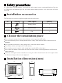
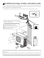
R410A MULTI SPLIT SERIES ROOM AIR CONDITIONER
OUTDOOR UNIT
INSTALLATION MANUAL
AU282XHERA
AU342XHERA
NO.0010577255
A
Please read this manual carefully before installing the units.
Please keep this manual safely for future use.
Contents
Cautions ....................................................................................................................... 1-2
Safety precautions........................................................................................................ 3-4
Installation accessories..................................................................................................
4
Choose the installation place.........................................................................................
4
Installation dimensions(mm).......................................................................................... 4
Installation drawings of indoor and outdoor units........................................................
5
Matching of the indoor and outdoor units...................................................................... 6-7
Power source.................................................................................................................
8
Limitations on the installation...................................................................................... 8-9
Refrigerant piping work........................................................................................... 10-11
Purging method: to use vacuum pump......................................................................... 12
Wiring work............................................................................................................... 13-15
Test running.................................................................................................................. 16
Items to confirm...........................................................................................................
16
Trouble shooting........................................................................................................... 17
Cautions
Disposal of the old air conditioner
Before disposing an old air conditioner that goes
out of use, please make sure it's inoperative and
safe. Unplug the air conditioner in order to avoid
the risk of child entrapment.
It must be noticed that air conditioner system
contains refrigerants, which require specialized
waste disposal. The valuable materials contained
in a air conditioner can be recycled. Contact your
local waste disposal center for proper disposal of
an old air conditioner and contact your local
authority or your dealer if you have any question.
Please ensure that the pipework of your air
conditioner does not get damaged prior to being
picked up by the relevant waste disposal center,
and contribute to environmental awareness by
insisting on an appropriate, anti-pollution method
of disposal.
Disposal of the packaging of your new air
conditioner
All the packaging materials employed in the
package of your new air conditioner may be
disposed without any danger to the environment.
The cardboard box may be broken or cut into
smaller pieces and given to a waste paper disposal
service. The wrapping bag made of polyethylene
and the polyethylene foam pads contain no
fluorochloric hydrocarbon.
Consult your local authorities for the name and
address of the waste materials collecting centers and
waste paper disposal services nearest to your house.
Safety Instructions and Warnings
Before starting the air conditioner, read the
information given in the User's Guide carefully. The
User's Guide contains very important observations
relating to the assembly, operation and maintenance
of the air conditioner.
The manufacturer does not accept responsibility for
any damages that may arise due to non-observation
of the following instruction.
Damaged air conditioners are not to be put into
operation. In case of doubt, consult your supplier.
Use of the air conditioner is to be carried out in
strict compliance with the relative instructions set
forth in the User's Guide.
Installation shall be done by professional people,
don't install unit by yourself.
For the purpose of safety, the air conditioner must
be properly grounded in accordance with
specifications.
Always remember to unplug the air conditioner
before opening inlet grill. Never unplug your air
conditioner by pulling on the power cord. Always
All these valuable materials may be taken to a waste grip plug firmly and pull straight out from the outlet.
collecting center and used again after adequate
recycling.
1
Cautions
All electrical repairs must be carried out by
qualified electricians. Inadequate repairs may result
in a major source of danger for the user of the air
conditoiner.
Do not damage any parts of the air conditioner
that carry refrigerant by piercing or perforating the
air conditioner's tubes with sharp or pointed items,
crushing or twisting any tubes, or scraping the
coatings off the surfaces. If the refrigerant spurts
out and gets into eyes, it may result in serious eye
injuries.
Do not obstruct or cover the ventilation grille of
the air conditioner. Do not put fingers or any other
things into the inlet/outlet and swing louver.
4. The wiring method should be in line with the local
wiring standard.
5. The power cable and connecting cable are selfprovided. All the cables shall have got the local
authentication certificate. During installation, when
the connecting cables break off, it must be assured
that the grounding wire is the last one to be broken
off.
6. The breaker of the air conditioner should be allpole switch; and the distance between its two contacts
should be no less 3mm. Such means for disconnection
must be incorporation in the fixed wiring.
7. The waste battery shall be disposed properly.
Do not allow children to play with the air
conditioner. In no case should children be allowed
to sit on the outdoor unit.
Specifications
The refrigerating circuit is leak-proof.
The machine is adaptive in following
situation
1. Applicable ambient temperature range:
Indoor
Maximum:D.B/W.B
Minimum:D.B/W.B
32 C/23 C
18 C/14 C
Outdoor
Maximum:D.B
Minimum:D.B
43 C/26 C
10 C/6 C
Maximum:D.B
Minimum:D.B
Maximum:D.B/W.B
Minimum:D.B/W.B
27 C
20 C
24 C/18 C
-15 C
Cooling
Heating
Indoor
Outdoor
2. If the supply cord is damaged, it must be replaced
by the manufacturer or its service agent or a similar
qualified person.
3. If the fuse on PC board is broken please change it
with the type of T 3.15A /250VAC or T 25A/250VAC.
Please check the circuit diagram about the fuse
replaced.
2
Safety precautions
To ensure proper installation, please read this safety precautions carefully before the installation. After
installation, start the unit correctly and ensure that you show the customer how to operate and maintain
the units.
WARNING! Incorrect operations may result in severe consequences of death or serious injuries.
CAUTION! Incorrect operations may result in injuries or machine damages; in some cases may
cause serious consequences.
WARNING
Installation work must be carried out by professional qualified people, do not install the unit by
yourself. Incorrect installation will cause water leakage, electric shock and potentially fire.
Install the unit as per the manual. Incorrect installation will cause water leakage, electric
shock or fire risk.
Be sure to use specified accessories and parts. Otherwise, water leakage, electric shock, fire risk
or unit falling down may occur .
Mounting position must be strong enough to hold the unit. Or, the unit will potentially fall down
causing injuries.
When installing the unit, take in consideration storms and high winds. Incorrect installation may
cause the unit to fall down.
All electric work should be carried out by experienced personnel as per current regulations and
this manual. Incorrect installation or undersized electric cable may cause electric shock or fire risk.
All circuits must be earthed. Ensure that no external forces will affect the terminal block and electric
cable. Poor wiring and installation may cause fire risk.
Arrange wire connection between connecting the indoor and outdoor power supply correctly. Fix
terminal cover firmly to avoid overheating, electric shock or even fire risk.
In the case of a refrigerant leakage during unit installation, keep the room well ventilated.
Check the unit upon installation. Be sure there is no leakage. Refrigerant will induce a poisonous
gas subject to heat.
Isolate power supply before touching terminal block.
WARNING
All units shall be earthed. The earth must not be connected to a gas pipe, water pipe, or telephone
line. Poor earthing could cause electric shock.
Be sure to install a circuit breaker to avoid electric shock.
Arrange water drainage according to this manual. Cover pipe with insulation materials to prevent
condensation occuring. Improper installation of water drainage will cause water leakage.
To maintain good picture or reduce noise, keep the unit at least 1m from T.V. or radio,
when installing the communication wire and power supply. (If the radio wave is relatively strong,
1m is not enough to reduce the interference).
Do not install the unit in following places:
(a) Oil mist or oil gas exists, such as kitchen, or, plastic parts may age, or water leakage.
(b) Where there is corrosive gas. Copper tube and welded part may be damaged due to corrosion
causing leakage.
3
Safety precautions
(c) Where there is strong radiation. It will affect the unit's control system, causing malfunction of the unit.
(d) Where there are flammable gas, dirt, and volatile matter (thinner, gasoline) exist, these items will cause
a fire risk.
Installation accessories
The following accessories are supplied together with the outdoor unit.
No.
Drawing
Name of parts
Quantity
1
Drainage elbow
1
2
Rubber cushion
4
3
Clap
1
Choose the installation place
Place, robust not causing vibration, where the body can be supported sufficiently.
Place, not affected by heat or steam generated in the vicinity, where inlet and outlet of the unit are not
disturbed.
Place, possible to drain easily, where piping can be connected with the outdoor.
Place,where cold air can be spread in a room entirely.
Place, nearby a power receptacle, with enough space around.(Refer to drawings).
Place, where the distance of more than 1m from televisions, radios, wireless apparatuses and fluorescent
lamps can be left.
In the case of fixing the remote controller on a wall, place where the indoor unit can receive signals when
the fluorescent lamps in the room are lightened.
Installation dimensions(mm)
380
416
340
830
950
185
1068
4
580
185
Installation drawings of indoor and outdoor units
1. Do not connected the embedded branch piping and the outdoor unit when only carrying out piping work
without connecting the indoor unit in ordor to add another indoor unit later. Make sure no dirt or mositure
gets into eigher side of the embedded branch piping.
2.It is impossible to connect the indoor unit for one room only. Be sure to connect at least 2 rooms.
Arrangement of piping directions
More than 5cm
Rear left
Mo
re th
an 1
Left
Rear right
Right
0cm
Below
Wrap the insulation pipe with the finishing
tape from bottom to top.
Attention must be
paid to the rising up
of drain hose
Cut thermal insulation pipe to an
appropriate length and wrap it with tape,
making sure that no gap is left in the
insulation pipe's cut line.
mor
mo
re
e th
0
an 1
cm
tha
n1
0cm
t
re
mo
m
0c
n6
ha
mo
re
tha
n2
5cm
If there is the danger of the unit falling or overturning, fix the unit with foundation bolts, or with wire or
other means.
If the location does not have good drainage, place the unit on a level mounting base(or a plastic pedestal).
Install the outdoor unit in a level position. Failure to do so may result in water leakage or accumulation.
5
Matching of the indoor and outdoor units
WARNING!
Combinations those marked * would not be applied where the temperature in winter is too low and in
summer is too higher to avoid bad heating or cooling effect.
For AU282XHERA
Combination
1:2
1:3
1:4
A
B
C
D
07
09
12
12
14
14
18
07
07
07
07
07
07
07
09
09
09
09
09
09
12
12
12
12
12
14
07
07
07
07
07
07
07
07
07
07
07
07
07
09
09
09
09
09
09
18
18
14
18
14
18
18
07
07
07
09
09
09
09
09
09
09
09
12
12
12
12
12
14
14
14
07
07
07
07
07
07
07
07
07
09
09
09
09
09
09
09
09
09
12
12
14
18
09
12
14
18
09
12
14
18
12
14
12
14
18
14
18
14
07
07
07
07
07
09
09
09
09
09
09
09
09
09
09
09
12
12
12
07
09
12
14
18
09
12
14
18
09
12
14
18
09
12
14
12
14
12
6
Remark
*
*
*
*
*
*
*
*
*
*
*
*
*
*
*
*
*
*
*
*
*
*
*
Matching of the indoor and outdoor units
For AU342XHERA
Combination
1:2
1:3
1:4
A
B
C
D
12
14
14
18
07
07
07
07
07
09
09
09
09
09
09
12
12
12
12
12
14
14
07
07
07
07
07
07
07
07
07
07
07
07
07
07
07
07
07
09
09
09
09
09
09
09
12
18
14
18
18
07
07
09
09
09
09
09
09
09
12
12
12
12
12
14
14
14
14
07
07
07
07
07
07
07
07
07
07
07
09
09
09
09
09
09
09
09
09
09
09
09
12
12
14
18
12
14
18
09
12
14
18
12
14
12
14
18
14
18
14
18
07
07
07
07
09
09
09
09
12
12
14
09
09
09
09
12
12
09
09
09
09
12
12
12
12
09
12
14
18
09
12
14
18
12
14
14
09
12
14
18
12
14
09
12
14
18
12
14
12
12
7
Remark
*
*
*
*
*
*
*
*
*
*
*
*
*
*
*
*
*
*
*
*
*
*
*
*
*
*
*
*
Power source
Before inserting power plug into receptacle, check the voltage without fail. The power source is the
same as the corresponded name plate.
Install an exclusive branch circuit of the power.
A receptacle shall be set up in a distance where the power cable can be reached. Do not extend the
cable by cutting it.
Limitations on the installation
1.Precautions on installation
Check the strength and level of the installation ground so that unit will not cause any operating vibration
or noise after installation.
In accordance with the foundation drawing in fix the unit securely by means of the foundation bolts.
It is best to screw in the foundation bolts unit their length are 20 mm from the foundation surface.
2.Selecting a location for installation of the indoor units
The maxinum allowable length of refrigerant piping, and the maxmum allowable height
difference between the outdoor and indoor units, are listed below.
(The shorter the refrigerant piping, the better the performance. Connect so that the
piping is as short as possible. Shortest allowable length per room is 3m)
Outdoor unit capacity class
AU282XHERA AU342XHERA
Piping to each indoor unit
25m max.
Total length of liquid piping between all units
60m max.
8
Limitations on the installation
3. Limitations values on the piping work .
L1
A
h
L2
B
H+
L3
C
HL4
D
The piping length information, please refer the following table.
Item
Unit
Descriptions
Standard
Maximum
A, B, C,D liquid pipe mm Size of the liquid side connection pipe
6.35
A, B, C,D Gas pipe
9.52
/
mm Size of the gas side connection pipe
/
L1 (one way)
m
Pipe length when the compressor connects with two indoor units
10
25
L2 (one way)
m
Pipe length when the compressor connects with two indoor units
10
25
L3 (one way)
L4 (one way)
m
m
Pipe length when the compressor connects only one indoor unit
Pipe length when the compressor connects only one indoor unit
10
10
25
25
L1+L2+L3+L4
m
Total liquid piping length(It is no need to charge additional
refrigerant within this value)
40
60
h
m
Drop between every two indoor units
1
5
H+
m
Drop between the outdoor unit and the indoor unit
5
15
H-
m
Drop between the outdoor unit and the indoor unit
5
10
9
Refrigerant piping work
1. Selection of pipe
To this unit, both liquid and gas pipes shall be insulated as they become low temperature in operation.
Use optional parts for piping set or pipes covered with equivalent insulation material.
Liquid pipe
6.35mm ( 1/4'' ) x 0.8mm
Gas pipe
9.52mm ( 3/8'' ) x 0.8mm
2. Connection of pipe
Apply refrigerant oil on half union and flare nut.
To bend a pipe, give the roundness as large as possible not to crush the pipe.
Connecting the pipe of gas side firstly makes working easier.
Half union
Flare nut
Spanner
Torque wrench
Forced fastening without careful centering may damage the threads and cause a
leakage of gas.
Pipe Diameter ( )
Fastening Torque
Liquid Side 6.35mm (1/4'')
18N.m
Gas Side 9.52mm (3/8'')
50N.m
3. Attaching Drain-Elbow
If the drain-elbow is used, please attach it as figure.
10
Refrigerant piping work
4.Cutting and Flaring work of piping
Pipe cutting is carried out with a pipe cutter and burs must be removed.
After inserting the flare nut, flaring work is carried out.
A
Size A (mm)
Pipe diameter*
Liquid side
6.35mm(1/4")
0.8~1.5
Gas side
9.52mm(3/8")
1.0~1.5
Flare tooling die
Incorrect
Correct
Lean
Damage of flare
Crack
Partial
Too outside
5.On drainage
Please install the drain hose so as to be downward slope without fail.
Please don't do the drainage as shown below.
Less than 5cm
It becomes high midway.
The end is immersed in
water
It waves.
It gap with the ground
ts too small.
There is the bad smell
from a ditch.
Please pour water in the drain pan of the indoor unit, and confirm that drainage is carried out serely
to outdoor.
In case that the attached drain hose is in a room, please apply heat insulation to it without fail.
11
Purging method: to use vacuum pump
Liquid stop valve
1 .Detach the service portis cap of 3-way valve, the valve
rod's cap for 2-way valve and 3-way valves, connect the
service port into the projection of charge hose (low) for
gaugemanifold. Then connect the projection of charge
hose (center) for gaugemanifold into vacuum pump.
Gas stop valve
2 way valve
3 way valve
Gauge maifold(R410A)
Vacuum pump(R410A)
2 .Open the handle at low in gaugemanifold, operate
vacuum pump. If the scale-moves of gause (low) reach
vacuum condition in a moment, check 1 again.
3 .Vacuumize for over 15min. And check the level gauge
which should read -0.1MPa (-76 cm Hg) at low pressure
side. After the completion of vacuumizing, close the
handle 'Lo' in the vacuum pump. Check the condition of
the scale and hold it for 1-2min. If the scale-moves back
in spite of tightening, make flaring work again, then
return to the beginning of 3 .
Open
Close
2 way valve
3 way valve
900
Service port
4 .Open the valve rod for the 2-way valve to and an angle
of anticlockwise 90 degree. After 6 seconds, close the 2way valve and make the inspection of gas leakge.
5 .No gas leakage?
In case of gas leakage, tighten
parts of pipe connection. If
leakage stops, then proceed 6
steps.
900 for 6 sec.
If it does not stop gas leakage, discharge
whole refrigerants from the service port.
After flaring work again and vacuumize,
fill up prescribed refrigerant from the gas
cylinder.
2 way valve
6 .Detach the charge hose from the service port, open 2-
6
3 way valve
6
way valve and 3-way. Turn the valve rod anticlockwise
until hitting lightly.
2 way valve
7 .To prevent the gas leakage, turn the service ports cap,
the valve rodis cap for 2-way valve and 3-way's a little
more than the point where the torque increases suddenly.
3 way valve
Valve rod cap
Valve rod cap
Service port cap
3 way valve
8 .Take the same steps from 1 to 7 for each ways to
ensure a completely vacuum for the whole system.
CAUTION: If the refrigerant of the air conditioner leaks,
it is necessary to make all the refrigerant out. Vacuumize
first, then charge the liquid refrigerant into air conditioner
according to the amount marked on the name plate.
12
9.52mm
(3/8")
2 way valve
6.35mm
(1/4")
3 way valve
9.52mm
(3/8")
2 way valve
6.35mm
(1/4")
3 way valve
9.52mm
(3/8")
2 way valve
6.35mm
(1/4")
3 way valve
9.52mm
(3/8")
2 way valve
6.35mm
(1/4")
To indoor unit A
To indoor unit B
To indoor unit C
To indoor unit D
Wiring work
1. Electric wiring
Note:
The air conditioner must use special circuit , and wiring by the qualified electrician according to the wiring
rules specified in national standard.
The grounding wire and the neutral wire shall be strictly separated. Connect the neutral wire with grounding
wire is incorrect.
The electric leakage breaker must be installed.
All the electric wire must be copper wire.When wiring,there shall keep a proper distance between the
power line and communication wire to avoid twist together. Otherwise,signal disturbance will occur,and
the air conditioner can not operate normally. Power supply: 1PH, 220-230V~, 50Hz.
The wiring method of power line is Y connection. If the power line is damaged, in order to avoid risk
of electric shock, it must be replaced by the manufacturer or its repair center or other similar qualified
person.The connecting cable must be shielded.
Fuse: T3.15A 250VAC T25A 250VAC (Please check with the outdoor unit wiring diagram.)
Please check the circuit diagram about the fuse replaced.
2. Wiring method
Wiring method of orbicular terminals
For the connection wire with orbicular terminals, its wiring method is as shown in
the right figure: remove the connecting screw, put the screw through the ring on the
Wiring Method for
Ring Terminal Block
end of the wire, then connect to the terminal block and fasten screw.
Wiring method of straight terminals
For the connection wire without orbicular terminals, its wiring method is: loosen
the connection screw, and insert the end of the connection wire completely into the Terminal block, then
fasten the screw. Slightly pull the wire outwards to confirm it is firmly held.
Correct Pressing
Wrong Pressing
Terminal
block
Pressing
Clamps
Crimp connection method for wires without terminals
Connect the wire with
same diameter to the
two sides of the terminal
Do not connect the
wire with same diameter
to the same side
13
Do not connect the
wire with different
diameters
Wiring work
Crimp connection method for connection wire
After connection,the wire must be fastened by wire cover. The wire cover shall press on the protection
coat of the connection wire,as shown in right top figure.
Note:When connecting the wiring,confirm the terminal number of indoor and outdoor units carefully.
Incorrect wiring will damage the controller of air conditioner or the unit can not operate.
3. Wiring method of outdoor unit:
Power line
Remove the repair board of the outdoor unit and loosen the wire cover A,then put the live wire, neutral
wire and grounding wire through the wire cover ,and connect them to terminal block correspon
dingly. After connection, fasten wire cover to its previous state.
Communication wire of indoor unit.
Loosen wire cover , put the communication wire through the wire cover B, and connect them to
terminal block correspondingly. After connection, fasten wire cover B to its previous state.
Note: Power line and communication wire are provided by consumers themselves.
Terminal block
Cord anchorage A
Cord anchorage B
Valve cover
4. Wiring method of indoor unit
Loosen wire cover and connect the power line and communication wire of indoor unit to the
terminal correspondingly.
Note:
When connecting power line to power supply terminal, please pay attention to the following items:
Do not connect the power line with different dimensions to the same connection wire end.
Improper contact will cause heat generation.
Do not connect the power line with different dimensions to the same grounding wire end.
Improper contact will affect protection.
Keep a proper distance between the communication wire and the power line. Otherwise, abnormal
communication will occur because of disturbance. And also, the communication wires should be
shielded wire, and the shield cover should be grounded on the outdoor unit.
Do not connect the power line to the connecting end of communication wire.
Incorrect connection will cause damage to the connected unit.
14
Wiring work
5. Example wiring diagram.
Indoor unit D
1(L) 2(N)
P
Indoor unit C
Q
1(L) 2(N)
Indoor unit A
Indoor unit B
C1 C2
Power supply cable:
H05RN-F 3G (5.0~8.0)mm2
1(L) 2(N)
C1
(P)
C2
(Q)
3
L
4
1(L) 2(N)
3
4
N
Communication cable (Shield
wire):
H05RN-F 2 X (0.75~1.5)mm2
Connecting cable:
H05RN-F 3G (1.5~2.5)mm2
30A
Outdoor unit
1PH, 220-230V~, 50Hz
Please refer to the indoor unit installation manual to find detailly how to set and check the communication
address.
Incorrect address setting will cause abnormal to the system.
6. After installation, please fill in the following table for easy daily maintenance:
Indoor unit NO.
Room name
Model of indoor unit
A
B
C
D
15
Serial no.
Test running
Before starting the test running, please confirm the following works have been done successfully.
1) Correct piping work;
2) Correct wiring work;
3) Correct match of indoor and outdoor unit;
4) Proper recharge of refrigerant if needed;
5) Correct indoor unit addresses setting.
Make sure that all the stop valves are fully open.
Check the voltage supplied to the outdoor and indoor units, please cinfirm that is 230V.
Test running.
1) If the temperature is lower than 16 C, it is impossible to test cooling with remote controller, and also
when the temperature is higher than 30 C, it is impossible to test heating.
2) To test cooling, set the lowest temperature at 16 C. To test heating,set the highest temperature, at
30 C.
3) Please check both cooling and heating operation of each unit individually and then also check the
simultaneous operation of all indoor units.
4) After ruuning the unit for about 20 minutes, check the indoor unit outlet temperature.
5) After the unit is stopped, or working mode changed, the system will not start again for about 3 minutes.
6) During cooling operation, frost may ocur on the indoor unit or pipes, this is normal.
7) Operate the unit according to the operation manual. Please kindly explain to our customers how to
operate through the instruction manual.
O
O
O
O
Items to confirm
Check items for test run, put mark "
in
".
Gas leakage from pipe connection?
Heat insulation treatment of pipe connection?
Are the connection wiring of indoor and outdoor unit firmly inserted into the terminal block?
Is the connection wiring of indoor and outdoor firmly fixed?
Is drainage securely arranged?
Is the ground wire securely and firmly connected?
Is power supply voltage abided by electric code?
Is there any noise?
Does cooling perform normally?
Does room temperature regulator operate normally?
16
Trouble shooting
FAILURE
CODE
1
2
STATE OF
LED 5-4-3-2-1
TROUBLE
SHOOTING
Faulty defrost sensor Te
Faulty sensor Tao
Sensor disconnected, or broken, or short circuit
Sensor disconnected, or broken, or short circuit
3
Faulty sensor Ts
Sensor disconnected, or broken, or short circuit
4
Faulty sensor Td
POSSIBLE REASONS
Sensor disconnected, or broken, or short circuit
Over current of the system, or broken of the current
5
Input overcurrent
sensor,or malfunction with indoor or outdoor fan
motors, or faulty PCB.
Abnormal communication Wrong connection, or the wires be disconnected, or
6
between indoor and outdoor wrong address setting of indoor units, or faulty
units
PCB, or faulty power supply
High pressure switch is disconnected, or high
pressure switch worked, or Tc too high and faulty
System high pressure
9
outdoor fan motor when cooling, or faulty indoor
protection
fan motors when heating, or refrigerant
overabundance
Low pressure switch is disconnected, or low
System low pressure
pressure switch worked, or Te too low and faulty
10
protection
outdoor fan motors when heating, or faulty indoor
fan motor when cooling, or refrigerant shortage
IPM over current, or short circuit, or IPM
11
IPM protection
temperature too high, or IPM input voltage too
low,or faulty SPDU(or ISPM).
12
EEPROM fault
Faulty outdoor unit PCB
Serious lack of refrigerant of the system, or the
Over hot protection of
13
ambient temperature too high, or PMVs be
compressor
blocked
Ambient tempreatrue too high, or outdoor fan be
Over
hot
protection
of
SPDU
14
blocked, or bad air circulation of outdoor unit
(or ISPM)
Fan is blocked, or the terminal is disconnected
15
DC fan motor fault
from the PCB
Faulty 4-way valve
Coil of 4-way valve is disconnected, or faulty
16
switching on
outdoor PCB
17
Faulty sensor Tc
Sensor disconnected, or broken, or short circuit
21
Faulty sensor Toci
Sensor disconnected, or broken, or short circuit
23
Low voltage protection
VDC<194V, too low voltage from power source
High voltage protection
24
VDC>400V, too high voltage from power source
Abnormal communication Communication cables broken, or not be well
25
between main PCB and connected, or faulty main PCB, or faulty SPDU(or
SPDU(or ISPM)
ISPM)
26
Compressor be locked
Faulty compressor or SPDU(or ISPM)
27
Compressor vibration too big Faulty compressor
28
Compressor lose position Faulty SPDU(or ISPM)
29
Faulty compressor start
Faulty compressor or SPDU(or ISPM)
Faulty position checking
30
Faulty SPDU(or ISPM)
circuit
31
Compressor broken
Faulty compressor or SPDU(or ISPM)
Take off the plastic cover on the right side of the unit, you can find the LEDs near the communication terminal.
Symbol means the LED is ON, and symbol means the LED is OFF.
17
HAIER GROUP
Qingdao Haier Air Conditioner Electric Co., Ltd.
Address: Haier Garden, Qianwangang Road, Economic Development Zone,
Qingdao, Shandong 266555, P.R.China
Web Site: http://www.haier.com