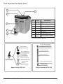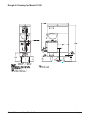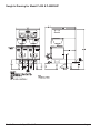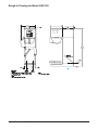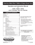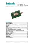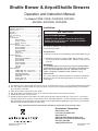
1
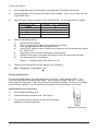
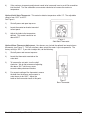
Shuttle Brewer & Airpot/Shuttle Brewers Operation and Instruction Manual For Models P300E, P400E, P400ESHP, RAP300E, RAP400E, RAPS300E, RAPS400E Table of Contents Installation and Start-up ....................................... 1-2 Warning Labels ...........................................................3 Operation .......................................................... 4 Adjustments ........................................................ 5-8 Care and Cleaning ............................................... 9-10 Service ............................................................... 10-11 Troubleshooting Filling Problems ....................................... 12 Heating Problems ................................. 13 Brewing Problems ................................ 14 Parts Illustrations Models P300E & P400E ....................... 15 Model P400ESHP .....................................16 Model RAP400E ..................................... 17 Model RAPS400E ................................... 18 VSB-400................................................ 19 Shuttle CS-LL .......................................... 20 Rough-In Drawings Model P300........................................................... 21 Model P400 & P400ESHP ...................... 22 Model RAP300 ......................................... 23 Model RAP400 ........................................ 24 Model RAPS300 ....................................... 25 Model RAPS400 ..................................... 26 VSB-300 .................................................. 27 VSB-400 ................................................ 28 Wiring Diagrams P300E/P400E with 1 Batch Timer ......... 29 P300E/P400E with 2 Batch Timer........ 30 RAP300E/RAP400E................................31 RAPS300E/RAPS400E........................32 P400ESHP ...........................................33 Drawing #091-548 .................................34 Drawing #091-182 .....................................35 Installation: WARNING ELECTRIC SHOCK HAZARD! Installation of this appliance should be performed by qualified service personnel only. Improper installation could result in electrocution. See rough-in drawings in this manual for dimensions and locations of electric and water input. Set-Up/Position 1) Remove the brewer from the packing material and attach its legs. 2) Position the brewer on a strong, stable table or counter. Check the level front to back and side to side. Adjust the legs to the correct level. IMPORTANT: THE PERSON INSTALLING THIS APPLIANCE IS RESPONSIBLE FOR ENSURING THAT ELECTRIC AND WATER CONNECTIONS MEET THE REQUIREMENTS OF THE NATIONAL ELECTRIC CODE, NATIONAL PLUMBING CODE, AND ANY LOCAL ORDINANCES. The electric and water hook-up locations are behind the front panel. Remove the four screws fastening this panel for access to these connections. Water Hook-up 1) The water line may enter through holes on the rear or the bottom of the brewer. Use the right hand opening for water. 2) Use 3/8" copper or flexible water line to prevent strain. Do not use low temperature plastic tubing. The connection to the fill valve is 3/8" flare. 3) Water line pressure must be from 30 to 70 psi. 4) Hot (up to 160°F) or cold water may be used. Hot water offers faster recovery between brews. 5) Install a shut-off valve near the brewer. 6) Installing a filtering system can improve the taste of brewed coffee and extend the life of the brewer. If your water has high calcium (lime), chlorine, or iron content, this is especially important. The filter should be the lime inhibiting type if cold water is used. Contact your local water treatment professional regarding the type of filter you should use based on water quality and volume of water used. Prior authorization must be obtained from Grindmaster Corporation for all warranty claims. Grindmaster Corporation © Grindmaster Corporation, 1998 PRINTED IN U.S.A. 4003 Collins Lane Louisville, KY 40245 USA (502) 425-4776 (800) 695-4500 (USA & Canada only) (800) 568-5715 (Technical Service Only) FAX (502) 425-4664 www.grindmaster.com 0307 FORM # AM-309-08 Part # 090-077 Installation (con't) Electric Hook-up 1) The electric ratings for your brewer are printed on its nameplate. Typical electric ratings are: P300, P400, RAP300, RAP400 Optional 120/208V, 3.8kW, 18A or 120/240V 5.0kW, 21A, 1 phase Standard 120/208V, 5.0kW, 24A or 120/240V 6.6kW, 28A, 1 phase RAPS300, RAPS400 Standard 120/208V, 4.4KW, 21A or 120/240V, 5.6KW 24A, 1 phase P400ESHP Standard 440V, 12.5KW, 16.3A, 3 phase WYE If the brewer includes the three heater tank option C21A, the ratings will be different. Always see the nameplate for correct ratings. 2) The brewer should be connected to its own circuit with a fused disconnect switch or a circuit breaker near the brewer. 3) Attach the appropriately sized cord to the brewer with a cord grip for the 1 1/2" electric input opening. The cord may enter through the rear or bottom on the left side of the brewer. Use an oil resistant cord such as type SO, SOO, SAO, STOO, SEO, SJO, SJOO, SJTO, SJTOO, SJEO, HSO, HSOO, HSJO, or HSJOO. Alternatively, flexible conduit and type THHN wires may be used. Use only copper conductors. 4) Standard connection is 1 phase 3 wire. Connect the two lines to L1 and L2 on the terminal block. If the brewer is wired for three phase, a lug, L3, is provided on the terminal block. A neutral line must be connected to the N terminal. WARNING Never use the ground conductor as a neutral. This could cause electrocution. 5) The body of the brewer must be grounded. A ground lug is provided for this purpose. Start-up 1) Turn on the water supply to the brewer. Check for leaks. 2) Turn on the electric supply. The brewer will begin to fill. 3) Replace the front access panel. 4) Once the brewer is full, it will take 15 to 35 minutes to heat. The water hot light will turn on when up to temperature. 5) Insert the brew baskets and place a shuttle or airpot under the baskets. Brew at least one batch from each side. Check the level in the container to be sure the brew volume is correct. Remember that when using coffee, the level will be lower. Do this for both batch sizes when provided. The water must be hot to check the levels. If adjustments are needed, see the adjustments section of this manual. Shuttle Brewers & Airpot/Shuttle Brewers Page 2 Warning Labels The following warning labels were on your dispenser when it was shipped from the factory. They should remain on your dispenser in good, readable condition at all times. If one of your labels is missing or damaged, order a replacement label immediately. Part # A546-445 Located on front splash panel and lid of machine. Part # A546-020 (P-300), A546-129 (P-400) Located near warmer plates. Part # A546-020 (P-300), A546-129 (P-400) Located near water faucet. Part # A546-213 Located on front splash panel. Part # A71949 Located on brew baskets. CAUTION Hot liquid in brew basket could cause burns. Remove with care. Shuttle Brewers & Airpot/Shuttle Brewers Page 3 Operation CAUTION HOT LIQUID HAZARD! Water used for brewing coffee is very hot. Use caution when brewing, pouring, or transporting coffee. Accidental spills may result in severe burns. 1) RAPS Brewers require the accessory warmer base placed over the pegs on the brew shelf before brewing into a shuttle. Plug the base into the receptacle on the side of the brewer. The receptacle is only energized when a shuttle is in place. 2) Place an empty, warm shuttle or airpot on the shelf, counter, or accessory base (depending on model) under the brew head. Turn on the warmer if a shuttle is used. 3) If the shuttle is not warm, allow the warmer to heat the shuttle. Only a short brew of water will speed this. A cold shuttle will significantly lower the temperature of the brewed coffee. 4) Remove the filter basket and line with a filter paper. Paper size is 13 x 5 for the smaller basket, BB1.5, and 14 x 5 for the larger, BB2.0. 5) Place ground coffee in the filter basket. Your coffee supplier can help you select the right amount of coffee and grind. Coffee brewing experts recommend between 6.5 and 8 ounces of coffee per gallon of water for most applications. A full shuttle is 1.4 gallons and a full airpot is 0.80 gallon. 6) Slide the basket into the brewer making sure the spout lines up with the top of the shuttle or airpot. 7) Check that the correct batch size is selected. Check the WATER HOT light. If lit, press start. 8) Brew time is about 4 minutes for a full shuttle, less for airpots and half batches. After the brew, allow the coffee to drip for 1 to 2 minutes. CAUTION Coffee basket contains very hot water until the drip is completed. Early removal of a dripping basket could result in burns. 9) Dump the grounds from the basket and rinse for the next brew. Coffee is ready to serve. 10) The shuttle may be placed on remote warming stations. Use caution when moving a full shuttle. Shuttle Brewers & Airpot/Shuttle Brewers Page 4 Adjustments WARNING Electrical Shock Hazard! Dangerous electric voltages are present near adjustable components. All adjustments should be performed by qualified service personnel only. All adjustable components are located under the top cover. To access these parts: 1) Shut off the electric line to the brewer or unplug the brewer. 2) Remove the single screw fastening the top cover. Remove the top cover. 3) Pull forward and lift off the top cover. Brew Volume, Brew Timer The brew volume of the brewer is controlled by its timer. The batch size is directly proportional to the timer setting. The timer adjustment is located under the top cover. On twin brewers, there is one timer for each brew head. Depending on the model, American Metal Ware offers three types of timer adjustments. Look at the instructions for the type of timer you have. There will always be a small variation (+ 5%) in level from batch to batch. Note: Always adjust bypass before adjusting timer because bypass affects brew rate. Before making the timer adjustment, do the following: 1) Brew a batch of water to determine where the level falls. Using a stop watch, determine the current brew volume. 2) To determine the desired time setting, use the following formula: desired brew volume X current brew time desired brew time = _________________ current brew volume Adjusting the Timer Standard single batch timer: RAP and P models without half batch include this timer, (see Figure 1). This timer is adjustable from 1 to 8 minutes. After removing the cover, do the following: 1) 2) Use the timer label to make an approximate adjustment of the timer. Figure 1 Single Batch Timer After adjusting the timer, brew a batch of water to check the volume. Repeat adjustment, tweaking the timer knob until the volume is correct. Shuttle Brewers & Airpot/Shuttle Brewers Page 5 Two Batch Timer with Knob Adjustment, See Figure 2: This timer is adjustable from 15 seconds to 5 minutes. Locate the adjustment knobs under the top cover. Set this timer by adjusting the knob. The batch selector switch picks the adjustment potentiometer which the timer will see. Figure 2 Two Batch Timer Two Batch Timer with Counter Adjustment, See Figure 3: The two batch size timer may also be used with optional counter potentiometer to ease adjustments. Each batch size is adjustable from 00 to 99. The timer settings for this timer are tabulated on the table below. This chart is for making an approximate setting. You may need to click up or down to make fine adjustments to volume. Each number is about 3 seconds. Figure 3 Two Batch Timer w/Counter Adjustment Counter Settings for NCC Q4F-0300-341AM Timers Counter Setting Time (min:sec) 00 10 15 20 25 30 0:15 0:46 1:01 1:17 1:32 1:47 Counter Setting Time (min:sec) Counter Setting Time (min:sec) 35 40 45 50 55 60 2:03 2:17 2:31 2:45 2:59 3:13 65 70 75 80 85 99 3:26 3:39 3:53 4:06 4:20 5:00 Bypass Adjustment The bypass valve adjusts the amount of water which bypasses coffee grounds and dilutes the final brew (see Figure 4). The factory setting is no bypass. Bitter coffee results when the amount of ground coffee is too small. Therefore, if your coffee is brewing too strong, it is better to adjust the bypass valve instead of reducing the amount of coffee. BYPASS BYPASS VALVE VALVE Figure 4 Bypass Valve Shuttle Brewers & Airpot/Shuttle Brewers Page 6 To Adjust the Bypass: 1) Shut off and open brewer as described at the beginning of the adjustments section. 2) Locate the bypass valve for the brew head you wish to adjust. Valve is on the right and front of the BREW valve. 3) Open the valve (counter clockwise) to the desired setting. Use the table below as a guide: BYPASS SETTING closed 1 turn 2 turns 3 turns 4 turns 4) BYPASS: % OF TOTAL BREW 0 8 12 22 33 Measure the bypass setting: a) b) c) d) e) f) g) Remove the brew basket. Place an empty shuttle without its lid under the spray head. Place a measuring cup under the bypass nozzle. Press START and brew water for about thirty seconds or until measuring cup is almost full. Press STOP. Record the amount of water in the bypass measuring cup. Add this to the water in the shuttle and record, measure the total amount of water. The bypass percent is calculated as: Bypass % = (Bypass Volume/Total Volume) X 100 5) Tweak the valve adjustment until the bypass is set as desired. Note: The bypass is accurate to + 4%. Thermostat Adjustment The main thermostat adjusts the water temperature in the tank. Factory setting is 200°F. This is the ideal temperature for brewing most coffee. Water should never boil in the tank. If water is boiling, adjust the thermostat. There are two types of thermostats available. Mechanical is standard and solid state is optional. See the adjustment instructions for the thermostat in your brewer. Standard Mechanical Thermostat: 1) Shut off power and open cover. 2) Locate thermostat mounted on tank. See Figure 5. 3) Turn the shaft counter clockwise to decrease temperature, opposite to increase temperature. Figure 5 Mechanical Thermostat Shuttle Brewers & Airpot/Shuttle Brewers Page 7 4) If the maximum temperature adjustment needs to be increased, insert a small flat screwdriver into the shaft. Turn the calibration screw counter clockwise to increase the maximum temperature. Optional Solid State Thermostat: This control maintains temperature within 3°F. The adjustable range is from 155°F to 205°F. See Figure 6. 1) Shut off power and open top cover. 2) Locate thermostat on bracket mounted to front panel. 3) Adjust the knob to the temperature desired. This control cannot be set above 205°F. Figure 6 Solid State Thermostat Optional Brew Thermostat Adjustment: Your brewer may include the optional low temp/no brew thermostat, (see Figure 7). This will not allow a brew unless the water is up to temperature. The factory setting is 192°F. If you wish to adjust this, do the following: 1) Shut off power and remove top cover. 2) Locate the thermostat mounted on the water tank. 3) To increase the set point, turn the shaft clockwise. We do not recommend adjusting this above 192°F which may cause excessive delays between batches. 4) For accurate setting of the thermostat, remove the bulb from the brewer and immerse in water known to be 190°F. Adjust the knob so the thermostat closes at this point. Figure 7 Brew Thermostat Shuttle Brewers & Airpot/Shuttle Brewers Page 8 Cleaning WARNING Burn Hazard! Hot liquids and surfaces are present in this equipment. To avoid burns use caution when cleaning. Rinse hot parts with cold water before cleaning. Use gloves or a heavy cloth when removing hot parts from brewer. After Each Brew: 1) Dispose of grounds and rinse brew basket. 2) Rinse shuttle or airpot containers before reuse. Every Day: 1) Wash brew basket with warm soapy water. The wire basket is removable to aid cleaning. 2) Remove spray head(s), located above brew basket(s), using gloves or a heavy towel. Wash off coffee oils and clean any plugged holes. 3) Clean shuttles with warm soapy water and a brush or towel. 4) Clean airpots with warm soapy water and bottle brush. Be careful, glass interior breaks easily. Use only a soft cloth and warm soapy water or stainless steel polish on the outside to avoid scratches. 5) Wipe exterior of brewer with a damp cloth. Do not use abrasives which will scratch surface. 6) If shuttles are to be left on warmer all night, fill with water to avoid coffee oil burn-in. Shuttle Brewers & Airpot/Shuttle Brewers Page 9 Weekly or Bi-Weekly, Depending on Use 1) Fill shuttles with one gallon, 2/3 full, of hot water. 2) Pour into the shuttle liners the recommended concentration of urn cleaner (excessive amounts of cleaner will attack the stainless steel). Urn cleaners that have been used successfully: DIP-IT, manufactured by Economics Laboratories, Inc. 4 Corporate Park Drive White Plains, NY 10604 OXYLITE, manufactured by Avril, Inc., Syndet Division 601 N. Third Street Reading, PA 19601 3) Scrub the liner interior with a plastic bristle brush. 4) Remove the knurled nut at the top of the gauge glass and clean the glass with a small bottle brush. 5) Pour out the contents of the shuttle. 6) Remove the handle assembly of the shuttle faucet by unscrewing the plastic bonnet. 7) Gently wash the faucet seat cup with a soft cloth and warm soapy water. 8) Wash the faucet shank with a bottle brush. 9) Soak airpot pick-up tube assembly in hot soapy water. Urn cleaner may be used for stronger cleaning. 10) Clean the warmer and bottom of shuttle surfaces. These surfaces must be clean for proper heat transfer. 11) Polish the exterior of the brewer with stainless steel cleaner. Use the appropriate cleaner for brass, copper, or vinyl if these optional finishes are provided. Service The rest of this manual contains information to aid the service person who is working on this equipment. This page has information on performing common service tasks. Following this is the Troubleshooting section which can help diagnose problems which are divided into three basic systems: filling, heating, and brewing. Next is an illustrated parts breakdown which will help in the selection of repair parts. If further assistance is needed, call our Technical Service Department at (502) 425-2776 or 800-695-4500 (USA & Canada only) Monday - Friday between 8:00 am and 8:00 pm EST. Wiring diagrams are also provided. Locate the basic diagram for the model you are working with. If there are any options, see Diagram #091-548 (page 31 of this manual) which shows the wiring alterations for Shuttle Brewer & Airpot/Shuttle Brewer options. Shuttle Brewers & Airpot/Shuttle Brewers Page 10 Service (con't) Drain Water Tank Always empty the tank before shipping. WARNING Draining of tank should be performed by a qualified service technician. The tank contains very hot water. May cause severe burns. Note: Brewer may contain over 5 gallons of hot water. 1) Prepare a heat resistant container to drain tank water into. 2) Shut off power to the brewer. 3) Remove the front access panel. 4) Pinch or clamp the silicone hose connected to fill valve. 5) Disconnect hose from outlet barb on fill valve. 6) Place hose over drain and release clamp. 7) Allow the tank to drain completely. NOTE: It may be necessary to pinch the hose and stop the water before container is full. Carefully reinstall hose over fill valve outlet, then empty container. Repeat steps 4-7 completely to drain tank. Remove Brew Valve 1) Disconnect electric power to machine. 2) Remove top cover and remove wires and small tube from valve. 3) Tilt inlet of valve down and pull sideways out of spray tee. 4) Clamp rubber tubing and disconnect valve from tubing. Remove Heater 1) Disconnect power and remove top cover of brewer. 2) Disconnect wire leads to heater. 3) Remove tank cover by loosening retaining screw. Cover is lifted up with heater attached. Heater is then removed. 4) Replace heater with sealing washers in same configuration. When tightening nuts, hold element so it does not twist. 5) Replace tank cover ensuring O-ring seal is good. 6) Replace heater wires. Be sure all electrical connections are secure. Shuttle Brewers & Airpot/Shuttle Brewers Page 11 Troubleshooting: Filling, Heating, and Brewing Filling Problems The filling system consists of the following components: • Liquid Level Control, located behind the brewer front panel. • Liquid Level Probes, located on the tank top, secured by wing nut, under the top cover. • Fill Valve, located behind the front panel. Problem Overfilling water tank even when power is off. Overfilling water tank only when power is on. Tank does not refill. Possible Cause Service Check Fill valve not sealing properly. Water entering tank continuously, usually slowly. Disassemble valve and clean out dirt. Valve may need new plunger if seal is worn. Fill valve installed backwards. Look for direction of arrow on valve body. If arrow on valve is pointing toward water inlet, remove valve and install correctly. High electrode coated with lime or faulty. Jumper HI terminal on level control to metal enclosure stops fill. Remove electrode assembly and clean both probes. If this does not work, replace assembly. Missing or faulty connection of C terminal on level control to metal enclosure. Jumper from C terminal to metal body stops fill. Make secure connection of C to metal body. Fill valve connected to heat terminal on level control. Check connections. Connect black lead for valve to FILL on level control. Liquid level control is faulty. Jumper from HI to C or metal enclosure does not stop fill. Replace level control. No power at equipment. Nothing operates. Check main switch or circuit breaker, brewer's circuit breaker or power switch if provided. No water at equipment. Cracked water inlet fitting. Make sure all water supply line valves are open. Water strainer clogged. Water pressure before strainer but not after. Remove and clean or replace strainer's mesh. No power to level control. Check for 120V AC across H and N terminals on level control. If no voltage, check for loose or broken wires. Level control faulty. Disconnect probe wire to HI terminal on level control. Check for 120V at FILL terminal. If no 120V at FILL terminal, replace level control. Electrodes faulty. Tank fills only when probe wire is disconnected from HI terminal on level control. Replace electrodes. If no remedy, check for improper wiring or level probe tip touching metal. Fill valve faulty. 120V is across FILL and N on level control, but no fill. Disassemble valve and clean or replace plunger if frozen. If plunger is OK, coil may need replacement. Shuttle Brewers & Airpot/Shuttle Brewers Remedy Page 12 Troubleshooting: Filling, Heating, and Brewing Heating Problems The heating system consists of the following components: • Liquid Level Control, located behind the front enclosure panel. • Liquid Level Probes, located on the tank top, secured by wing nut, under the top cover. • Thermostat, located on the tank or on the front of top control panel under top cover. • Heater Relay, located in top control section under top cover. • Heating Elements, located on tank top under top cover. Problem Tank does not heat. Recovery time is very long. Possible Cause Low electrode faulty or covered w/lime. Service Check Jumper from XL terminal on level control to metal body allows heating. Remedy Clean electrodes, check wiring. If no remedy, replace electrodes. Level control faulty. Check for 120V beIf 120V is not at HEAT, replace level tween H and N tercontrol. minals on level control. If OK, jumper between XL and metal body and check for 120V between HEAT and N terminals. Thermostat faulty or out of calibration. Make sure thermostat is turned on. Jumper across thermostat allows heating. Recalibrate thermostat. If no remedy or thermostat does not cycle, replace thermostat. Heater relay coil faulty. (electric heat) Check for 120V across contactor coil. If correct voltage, but contactor not closing, replace contactor. Heater contactor contacts faulty. Check for heater volIf no continuity across contactor tage between each when it is closed, replace contactor. heater pole on contactor, and different pole. Heater faulty. Check resistance across elements with wires disconnected. If resistance is much different than 10 to 15 ohms, replace heater. Heater faulty. See above. See above. Low temp/no brew thermostat set too high. Water is above 190 degrees F, but HOT WATER light is off. Turn down brew thermostat, see adjustments. If you still need help, call our Technical Service Department at (502) 425-4776 or (800) 695-4500 (USA & Canada only) Monday thru Friday 8 am - 8 pm EST or an authorized service center in your area. Please have the model and serial numbers ready so that accurate information can be given. Prior authorization must be obtained from Grindmaster Corporation’s Technical Service Department for all warranty claims. Shuttle Brewers & Airpot/Shuttle Brewers Page 13 Troubleshooting: Filling, Heating, and Brewing Brewing Problems The brewing system consists of the following components: • Start and Stop, switches located in the top control panel. • Brew Timer, located in the top control section under the top cover. • Brew Valve, located in the top control section under the top cover. Problem Brew volume too large or too small. Brew volume erratic. (there is always some small variation from batch to batch) Brew will not start. Possible Cause Remedy Timer out of adjustment. Compare timer setting to Adjust timer. factory setting chart. Pressure not adequate at urn. Fill valve should cycle on and off frequently during brew cycle when all brew heads are used. If fill valve does not cycle or takes too long to refill, be sure water line is 3/8" and pressure is uninterrupted 30psi. Spray head clogged. Visual Clean all holes. Brew valves clogged with lime. Visual, inspect brew valve. Clean lime from valve. Seat cup or entire valve may need replacement. Timer faulty. Brew time does match timer setting. Timer not adjustable. Replace timer. Timer faulty. Measure brew time for inconsistencies. If time is different from batch to batch, replace timer. Pressure fluctuations at urn. Check pressure at urn inlet. Plumb water line so its pressure is not influenced by other appliances. Circuit breaker tripped or faulty. If circuit breaker button If tripped, find cause and reset. If is out, breaker is tripped. faulty, replace. Brew valve faulty. Stop switch faulty. Spray head will not stop dripping water. Service Check Check 120V across brew valve. Check for continuity across stop switch when not pressed. If 120V is across brew valve, but brew valve doesn't open, replace coil or valve. If no continuity, replace switch. Start switch faulty. Check 120V between S.S. and N on timer when start is pressed. If start switch does not provide 120V start signal, replace switch. Low temp/no brew thermostat set too high. Water is above 190°F (88°C), but HOT WATER light is off. Turn down brew thermostat, see adjustments. Timer faulty. Check 120V between H If no 120V BREW output from timer, and N on timer. If OK, replace timer. check for 120V between BREW and N on timer after pressing start. Boiling tank. If drip is from right side, check for water from overflow outlet at top of tank. Limed up brew valve. Visual check of valve. (spray heads normally drip slightly after brew) Shuttle Brewers & Airpot/Shuttle Brewers Turn down thermostat. If that doesn't cure, check for faulty thermostat or heater relay. Clean valve. Valve seal or entire valve may need replacement. Page 14 Parts Illustration for Models P300E & P400E Item Part # Description Item Part # Description 1 A545-034 LEG, 4” PLASTIC W/ SS FOOT 13 A725-081 BRASS SPRAY TEE W/ BYPASS TUBING 1 A545-015 LEG, 4” SS (OPTIONAL) 14 A530-009 BREW TIMER 0-8 MINUTES 2 A537-043 HOT WATER FAUCET W/ NUT 15 A585-021 SPRAY TUBING 3/8” ID X 5/8”OD X 6”LG 3 A531-035 TERMINAL BLOCK 16 A712-018 ELECTRODE ASSEMBLY 4 A531-026 TOGGLE SWITCH 17 A535-059 TANK HTR 6.6 KW @ 240V 5 A549-006 LIQUID LEVEL CONTROL BRD 18 A712-046 THERMOSTAT W/ GROMMET 6 APT400-105 SPRAY HEAD 19 A515027 DPST POWER RELAY 7 ACS-LL SHUTTLE W/ LOCKING LID 20 A585-023 OVERFLOW TUBE 1/2”OD X 5/16”ID 7”LG 8 ABB1.5SS BREW BASKET, SS 21 A515072 CIRCUIT BREAKER 10 AMP 9 A537-129 BREW VALVE 22 A718-111 BYPASS VALVE ASSEMBLY 10 A531-005 STOP SWITCH (before March 2000) 23 A718-198 FILL VALVE W/ FITTINGS (after 01-26-00) 10 A531-063 STOP SWITCH (after March 2000) 23 A537-154 FILL VALVE ONLY (after 01-26-00) 11 A531-004 START SWITCH (before March 2000) 23 A725-072 FILL VALVE RETROFIT KIT (before 01-26-00) 11 A531-062 START SWITCH (after March 2000) 24 A585-016 TUBING FILL 1.6’ LG & HOT WATER 1.5’ LG 12 A515016 PILOT LIGHT 25 A535-018 WARMER ELEMENT (below warmer shelf) 12 11 16 17 15 18 14 19 13 20 21 10 22 9 8 TOP - (COVER REMOVED) 7 6 5 23 4 24 25 3 2 FRONT 1 NOTE: THIS DRAWING SHOWS PARTS FOR THE MODEL P400E. ALL PARTS SHOWN ON THIS DRAWING APPLY TO THE MODEL P300E, EXCEPT THE QUANTITIES MAY CHANGE. DEPENDING ON THE OPTIONS INCLUDED, YOUR BREWER MAY HAVE DIFFERENT PARTS Shuttle Brewers & Airpot/Shuttle Brewers FRONT - (COVER REMOVED) Page 15 Parts Illustration for Model P400ESHP Item Part # Description Item Part # Description 1 A545-034 LEG, 4” PLASTIC W/ SS FOOT 15 A585-021 SPRAY TUBING 3/8” ID X 5/8”OD X 6”LG 1 A545-015 LEG, 4” SS (OPTIONAL) 16 A712-018 ELECTRODE ASSEMBLY 2 A537-043 HOT WATER FAUCET W/ NUT 17 A535-068 TANK HTR 3.7 KW @ 240V 3 A531-035 TERMINAL BLOCK 18 A712-046 THERMOSTAT W/ GROMMET 4 A531-026 TOGGLE SWITCH 19 A514005 CONTACTOR 5 A549-006 LIQUID LEVEL CONTROL BRD 20 A585-023 OVERFLOW TUBE 1/2”OD X 5/16”ID 7”LG 6 APT400-105 SPRAY HEAD 21 A515072 CIRCUIT BREAKER 10 AMP 7 ACS-LL SHUTTLE W/ LOCKING LID 22 A718-111 BYPASS VALVE ASSEMBLY 8 ABB1.5SS BREW BASKET, SS 23 A718-198 FILL VALVE W/ FITTINGS (after 01-26-00) 9 A537-129 BREW VALVE 23 A537-154 FILL VALVE ONLY (after 01-26-00) 10 A531-005 STOP SWITCH (before March 2000) 23 A725-072 FILL VALVE RETROFIT KIT (before 01-26-00) 10 A531-063 STOP SWITCH (after March 2000) 24 A585-016 TUBING FILL 1.6’ LG & HOT WATER 1.5’ LG 11 A531-004 START SWITCH (before March 2000) 25 A535-079 WARMER ELEMENT 240V (below warmer shelf) 11 A531-062 START SWITCH (after March 2000) not shown A515027 WARMER RELAY 12 A515016 PILOT LIGHT not shown A532-001 FUSE HOLDER 13 A725-081 BRASS SPRAY TEE W/ BYPASS TUBING not shown A532-010 FUSE 1A 14 A530-009 BREW TIMER 0-8 MINUTES not shown A515043 TRASFORMER STEP DOWN Shuttle Brewers & Airpot/Shuttle Brewers Page 16 Parts Illustration for Model RAP400E Item Part # Description Item Part # Description 1 A548-072 LEG, RUBBER (RAP400) 11 A515016 PILOT LIGHT 1 A545-004 LEG, PLASTIC 4” (OPTIONAL RAP 400) 12 A725-082 SPRAY TEE KIT W/ BYPASS PLUG 1 A548-090 LEG, PLASTIC PLUG (RAP300) 13 A530-009 BREW TIMER 0-8 MINUTES 2 A531-035 TERMINAL BLOCK 14 A585-021 SILICONE TUBING 3/8”ID X 5/8”OD X 6”LG 3 A549-006 LIQUID LEVEL BOARD 15 A712-018 ELECTRODE ASSEMBLY 4 AAP-3 AIRPOT 16 A535-059 TANK HTR 6.6 KW @ 240V 5 APT400-105 SPRAY HEAD 17 A712-046 THERMOSTAT W/ GROMMET 6 ABB1.5P BREW BASKET, PLASTIC 18 A515027 POWER RELAY 7 A537-129 BREW VALVE 19 A585-023 OVERFLOW TUBE 1/2”OD X 5’16ID X 7LG 8 A531-005 STOP SWITCH (before March 2000) 20 A515072 CIRCUIT BREAKER 10 AMP 8 A531-063 STOP SWITCH (after March 2000) 21 A718-198 FILL VALVE W/ FITTINGS (after 01-26-00) 9 A531-004 START SWITCH (before March 2000) 21 A537-154 FILL VALVE ONLY (after 01-26-00) 9 A531-062 START SWITCH (after March 2000) 21 A725-072 FILL VALVE RETROFIT KIT (before 01-26-00) 10 A537-043 HOT WATER FAUCET 22 A585-016 TUBING FILL 1.6’ LG & HOT WATER 3.75’ LG 11 10 9 15 16 14 17 13 18 12 19 20 8 7 6 TOP - (COVER REMOVED) 5 4 21 3 22 2 1 FRONT FRONT - (COVER REMOVED) Shuttle Brewers & Airpot/Shuttle Brewers Page 17 Parts Illustration for Model RAPS400E Item Part # Description Item Part # Description 1 A545-034 LEG, 4” PLASTIC W/ SS FOOT 16 A725-081 BRASS SPRAY TEE W/ BYPASS TUBING 1 A545-015 LEG, 4” SS (OPTIONAL) 17 A585-021 SPRAY TUBING 3/8” ID X 5/8”OD X 6”LG 2 A537-043 HOT WATER FAUCET W/ NUT 18 A712-018 ELECTRODE ASSEMBLY 3 A531-035 TERMINAL BLOCK 19 A535-010 TANK HEATER 5KW @ 240V 4 AABW-R ACCESSORY WARMER RIGHT 20 A712-046 THERMOSTAT W/ GROMMET 5 AAP-3 AIRPOT 3 LITER 21 A515027 DPST POWER RELAY 6 A549-006 LIQUID LEVEL CONTROL BOARD 22 A585-023 OVERFLOW TUBE 1/2”OD X 5/16”ID 7”LG 7 APT400-105 SPRAY HEAD 23 A515072 CIRCUIT BREAKER 10 AMP 8 ACS-LL SHUTTLE W/ LOCKING LID 24 A530-016 1/2 BATCH CUBE TIMER 9 ABB1.5SS BREW BASKET, STAINLESS STEEL 25 A718-111 BYPASS VALVE ASSEMBLY 10 A537-129 BREW VALVE 26 A531-025 MOMENTARY SWITCH 11 A531-005 STOP SWITCH (before March 2000) 27 A718-198 FILL VALVE W/ FITTINGS (after 01-26-00) 11 A531-063 STOP SWITCH (after March 2000) 27 A537-154 FILL VALVE ONLY (after 01-26-00) 12 A531-004 START SWITCH (before March 2000) 28 A515062 FUSE HOLDER 12 A531-062 START SWITCH (after March 2000) 29 A532-002 FUSE CLASS G 3 AMP 13 14 A550-159 A515016 BATCH SELECTOR SWITCH 30 A585-016 TUBING FILL 1.6’ LG & HOT WATER 1.5’ LG PILOT LIGHT 31 A550-279 SINGLE RECEPTACLE NEMA 5-15R GFCI 15 A554-043 POTENTIOMETER 12 13 14 18 19 17 20 16 21 15 22 23 11 24 10 25 9 TOP - (COVER REMOVED) 8 26 7 6 27 5 28 29 4 30 3 31 2 FRONT 1 FRONT FRONT - (COVER REMOVED) Shuttle Brewers & Airpot/Shuttle Brewers Page 18 Parts Illustration for Model VSB-400 Item Part # Description Item Part # Description 1 A545-034 LEG, 4” PLASTIC W/ SS FOOT 12 A725-081 SPRAY TEE KIT W/ BYPASS TUBING 1 A545-015 LEG, 4” SS (OPTIONAL) 13 A530-009 BREW TIMER 0-8 MINUTES 2 A531-035 TERMINAL BLOCK 14 A585-021 SILICONE TUBING 3/8”ID X 5/8”OD X 6”LG 3 A549-006 LIQUID LEVEL BOARD 15 A712-018 ELECTRODE ASSEMBLY 4 AVS-1.5 SHUTTLE VACUUM 16 A535-059 TANK HEATER 6.6 KW @ 240V 5 APT400-105 SPRAY HEAD 17 A712-046 THERMOSTAT W/ GROMMET 6 ABB1.5P BREW BASKET, PLASTIC 18 A515027 POWER RELAY 7 A537-129 BREW VALVE 19 A585-023 OVERFLOW TUBE 1/2”OD X 5/16”ID 7”LG 8 A531-005 STOP SWITCH (before March 2000) 20 A515072 CIRCUIT BREAKER 10AMP 8 A531-063 STOP SWITCH (after March 2000) 21 A718-111 BYPASS VALVE ASSEMBLY 9 A531-004 START SWITCH (before March 2000) 22 A718-198 FILL VALVE W/ FITTINGS (after 01-26-00) 9 A531-062 START SWITCH (after March 2000) 22 A537-154 FILL VALVE ONLY (after 01-26-00) 10 A537-043 HOT WATER FAUCET 22 A725-072 FILL VALVE RETROFIT KIT (before 01-26-00) 11 A515016 PILOT LIGHT 23 A585-016 TUBING FILL 1.6’ LG & HOT WATER 1.5’ LG Shuttle Brewers & Airpot/Shuttle Brewers Page 19 Parts Illustration for Shuttle CS-LL 5 6 4 Item Part # Description 1 A537-053 FAUCET MODEL ES 2 A522078 SHANK W/ CHROME BONNET 3 A718-018 GAUGE ASSEMBLY 4 A725-092 KIT, SHUTTLE LID A713-027 SS SHUTTLE COVER (not shown)* 5 A548-142 LID RETAINING CLIP 6 A548-140 A61365 LID STOPPER W/ O-RING 3 2 1 * S.S. Cover used until August 2001 A318-119P TOP GAGE FITTING A537-055 HANDLE A522026 WASHER UPPER GAGE A555-001 GAGE SHIELD A522132 BONNET NUT A522120 SPRING A522031 GAGE GLASS A537-047 PLASTIC STEM A537-049 UPPER FAUCET ASSEMBLY A522102 SILICONE SEAT CUP A522027 WASHER LOWER GAGE AA-958 GAGE BASE Upper Faucet A537-049 Shuttle Brewers & Airpot/Shuttle Brewers Gauge Assembly A718-018 Page 20 Rough-In Drawing for Model P-300 Shuttle Brewers & Airpot/Shuttle Brewers Page 21 Rough-In Drawing for Model P-400 & P-400ESHP Shuttle Brewers & Airpot/Shuttle Brewers Page 22 Rough-In Drawing for Model RAP-300 Shuttle Brewers & Airpot/Shuttle Brewers Page 23 Rough-In Drawing for Model RAP-400 Shuttle Brewers & Airpot/Shuttle Brewers Page 24 Rough-In Drawing for Model RAPS-300 Shuttle Brewers & Airpot/Shuttle Brewers Page 25 Rough-In Drawing for Model RAPS-400 Shuttle Brewers & Airpot/Shuttle Brewers Page 26 Rough-In Drawing for Model VSB-300 WATER W W W W IMS Shuttle Brewers & Airpot/Shuttle Brewers Page 27 Rough-In Drawing for Model VSB-400 Shuttle Brewers & Airpot/Shuttle Brewers Page 28 Wiring Diagram for P300E/P400E, with 1 Batch Timer NOTE: THIS DRAWING SHOWS COMPONENTS ON STANDARD MODEL ONLY. SEE 091-548 FOR WIRING OF BREWER OPTIONS Shuttle Brewers & Airpot/Shuttle Brewers Page 29 Wiring Diagram for P300E/P400E, with 2 Batch Timer NOTE: THIS DRAWING SHOWS COMPONENTS ON STANDARD MODEL ONLY. SEE 091-548 FOR WIRING OF BREWER OPTIONS Shuttle Brewers & Airpot/Shuttle Brewers Page 30 Wiring Diagram for RAP300E/400E NOTE: THIS DRAWING SHOWS COMPONENTS ON STANDARD MODEL ONLY. SEE 091-548 FOR WIRING OF BREWER OPTIONS Drawing #091-545 Shuttle Brewers & Airpot/Shuttle Brewers Page 31 Wiring Diagram for RAPS 300/400E NOTE: 1) TWO SETS OF RECEPTACLE COMPONENTS ONLY PROVIDED ON TWIN RAPS400E MODEL. DELETE GROUP IN DASHED BOX FOR RAPS300E. 2) THIS DIAGRAM SHOWS COMPONENTS ON STANDARD MODEL ONLY. SEE 091-548 FOR WIRING OF BREWER OPTIONS. Drawing #091-523 Shuttle Brewers & Airpot/Shuttle Brewers Page 32 Wiring Diagram for P-400ESHP Shuttle Brewers & Airpot/Shuttle Brewers Page 33 Wiring Diagram #091-548 NOTE: 1) ONE GROUP OF WARMER COMPONENTS PER BREW HEAD ON P AND RAPS MODELS. 2) TRANSFORMER MUST BE USED WHEN NEUTRAL LINE IS NOT PROVIDED. 3) IF MODEL RAP, DELETE WARMER COMPONENTS. 4) IF MODEL IS RAPS, DELETE WARMER LIGHT AND REPLACE WARMER ELEMENT WITH NEMA 6-15 RECEPTACLE. NOTES: 1) IF PROVIDED WITH OPTION C21A, THREE HEATERS, SEE HEATER WIRING DIAGRAM 091-182. 2) WHEN PROVIDED WITH OPTION C14, AUTOMATIC WARMER SHUTOFF, SUBSTITUTE ACTIVATED SWITCH FOR WARMER TOGGLE. Shuttle Brewers & Airpot/Shuttle Brewers Page 34 Wiring Diagram #091-182 NOTE: USE WIRE NUT FOR 1 - 1 CONNECTION T3 T2 A T2 T3 T2 T3 T3 T3 T3 T3 T3 T3 T3 T3 T3 1 T4 1 T1 T1 1 T4 1 T1 T1 T4 T4 T1 T4 T4 A B C D E T2 T3 T3 T1 T1 T2 F 5000 WATT / 240V HEATERS FOR THIS HEAT AND ELECTRIC SERVICE 2.0 KW - 120/208V - 1 PH - 3 WIRE - 9 AMPS 2.5 KW - 120/240V - 1 PH - 3 WIRE - 11 AMPS 4.0 KW - 120/208V - 1 PH - 3 WIRE - 18 AMPS 5.0 KW - 120/240V - 1 PH - 3 WIRE - 21 AMPS 5.5 KW - 120/208V - 1 PH - 3 WIRE - 27 AMPS 7.5 KW - 120/240V - 1 PH - 3 WIRE - 31 AMPS 7.5 KW - 120/208V - 1 PH - 3 WIRE - 38 AMPS 10.0 KW - 120/240V - 1 PH - 3 WIRE - 42 AMPS 11.5 KW - 120/208V - 1 PH - 3 WIRE - 54 AMPS 15.0 KW - 120/240V - 1 PH - 3 WIRE - 63 AMPS 11.5 KW - 120/208V - 3 PH - 4 WIRE - 31 AMPS 15.0 KW - 240V - 3 PH - 3 WIRE - 36 AMPS * WIRE PER FIG. A B C D E F * SEPARATE 120V REQUIRED FOR CONTROLS (3 AMP LOAD) * FOR 3 PHASE WIRING 1. MOVE WIRE 6 FROM L1 TO L3 2. CONNECT HEATER ACCORDING TO FIG. F ON CHART 3. FIG. F FOR 3 PH ONLY WIRES 5 6 7 8 ARE 8 AWG, 105°C 1 2 3 4 ARE 10 AWG, 105°C Shuttle Brewers & Airpot/Shuttle Brewers Page 35 Grindmaster® Coffee Grinders and Brewers • PrecisionBrew™ Brewing Systems • Espressimo® Espresso Machines Crathco® Hot Beverage Dispensers • Crathco® Cold and Frozen Beverage Dispensers • AMW Coffee and Tea Systems Tel (502) 425-4776 • Fax (502) 425-4664 • 1-800-695-4500 (USA & Canada only) P.O. Box 35020 • Louisville, KY 40232 • USA © Grindmaster Corporation, 1998 0307 Form # AM-309-08 www.grindmaster.com • email: [email protected] PRINTED IN USA Part # 090-077