1
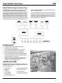
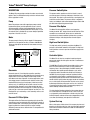
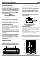
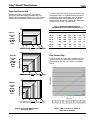
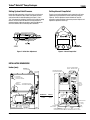
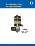
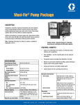
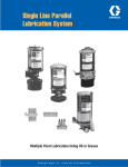
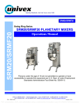
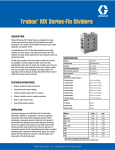
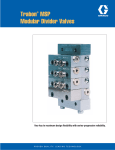
Meter-Flo® Pump Packages Circulating Oil Systems Trabon® Meterflo® Pump Packages 12608 Meterflo® Pump Packages For System Savings Meterflo packages are intended for relatively large systems (100 to 1,000 points), with a total requirement of up to 245 cubic inches per minute supplied by electric motor driven gear pumps. Meterflo pump packages are typically used with Trabon® MSP, MXP, and MGO series progressive divider valves, which accurately piston-proportion the oil input to a multiple number of lubrication points. A big advantage of the positive piston displacement is the reduction in total lube volume required as compared to unmetered systems. This results in much smaller pumps, tubing sizes, and filter capacity. Motor horsepower is also reduced, with savings in frame size and energy costs. Graco’s Meterflo pump packages come with a wide assortment of displacements, options, and accessories to handle a wide variety of applications. These pre-assembled packages are ready for connection to Trabon series progressive lube systems, operating in either a terminating or circulating mode. FEATURES/BENEFITS • Flooded suction pumps for maximum performance • Full rated output at rated pressure • Seven different displacements from 14 to 245 in3/min • System protected with 1,200 psi internal relief valve • External relief (adjustable) factory set @ 1,000 psi • 15 and 30 gallon reservoirs with level gauge, filler/breather, return line/pressure fill port, suction line fitted with strainer and shut-off valve for ease of service • Options and accessories include low level, high level, and pressure switches; pump housing safety covers; filters; controllers; and 115 to 460 VAC motors UNLIMITED APPLICATIONS Meterflo packages are used in a wide range of applications, from individual machines to high volume production lines. A few of the many applications include: • • • • • • Stamping presses Textile mills Transfer lines Plastic sheeters Printing presses Plastic molding machines • • • • Coil processing equipment Metal turning machines Primary metal mills Food processing equipment Page 2 Trabon® Meterflo® Pump Packages 12608 Description Pressure Switch Option The Meter-Flo pump package consists of various user selected options. These are listed below to help select the unit best suited for the application in mind. The pressure switch provides an electrical signal in case of excessive pressure, indicating a blockage or restriction in the lube system. This signal can be used to trip a warning device or to shut the machine down. The pressure switch is adjustable, factory set at 800 psi, with recommended settings at 50 to 100 psi above normal operating pressure highs. Pump Meter-Flo packages come with rugged gear pumps made of hardened steel gears, precision ground to assure a close fit, efficient operation and long-lasting dependability. An internal relief valve provides redundant protection for the pump, in case the external relief is disabled for any reason. Output capabilities range from 14 to 245 cu.in./min. Motor The gear pump is driven by a direct coupled 1/2 horsepower motor that can be specified as either 15/230 or 230/460 VAC. These are single phase foot mount 56 frame motors turning a 1725 RPM. Pressure Filter Option The Meter-Flo discharge filter utilizes a non-bypassing industry standard “HF2” design 10 or 20 micron element. Filter assemblies are available with either visual or combination visual/electrical element condition indicator set to a pressure differential of 50 psi, indicating the filter element requires changing. High Level Switch Option The high level switch is primarily used when the Meter-Flo package is utilized with automatic refill system. The high level switch provides an electric signal to shut off lube supply to the reservoir. Controller Option The Meter-Flo unit also has an optional control package to operate and monitor the lube system on either a continuous or intermittent cycle. Figure 1. Motor Starter Used with Graco® Controllers Reservoirs Reservoirs come in 15 and 30 gallon capacities, providing volume multiples witch are 30 to 500 times the maximum pump displacements. These large multiples allow for high volume draw-downs and return surges for circulating applications, such as stamping presses. Standard reservoir features include a top mounted filler/strainer, visual level gauge, 140 micron suction strainer, and a 1/2 in NPSF port for use with a return line or for pressurized filling. Reservoirs can be floor mounted by using four holes provided in the base flanges for 1/2 bolts. Top filling is made easy by a maximum reservoir height of less that 34 in. The filler/breather cap is retained by a chain assembly, and has a 30 mesh fill screen. Reservoir Fill Filter Option This option utilizes the Trabon non-bypassing style spin-on filter assembly to prevent contamination form entering the reservoir. It comes complete with a 0 to 160 psi pressure gauge and external bypass to protect the element against line surges and high differential pressures due to contamination. It is compatible with petroleum based oil. Page 3 The WMP Maxi-Flo will schedule lube periods on either a time basis or machine stroke/cycle count at a user determined frequency. Once a lube period begins, the WMP controller will also monitor lube system operation through a cycle switch or proximity switch attached to the divider valve. As long as the WMP receives the proper number of actuations from the cycle/proximity switch within a monitored interval for each lube period, system operation will be considered normal. If the monitor interval expires before the proper number of actuations occur, a fault signal will be generated. The fault can be caused by blockages, defective pump, open main line, etc., but this is a warning that the lube system is not operating properly and trouble shooting methods should be taken. The Lube Sentinel II option monitors the lube system when run on a continuous basis. Through the use of a timer circuit and a cycle/proximity switch mounted on a divider valve, the Lube Sentinel II detects reduction in flow rates (clogged filter) as well as no-flow (line blockage) and signals this malfunction. System Start-up When a lube system is first started, it is necessary to prime and bleed the air out of the lube lines, and check for proper operation. Refer to Graco Bulletins L30103 and L30101 for information on these procedures. Trabon® Meterflo® Pump Packages 12608 APPLICATION INFORMATION to that valve’s inlet, and (D) the maximum loss for the worst case line from the divider valve used in (C) to the lube point for that line. An example is shown in Figure 2. Calculating Flow Requirements Clearly, an approximate layout of the system will be required to arrive at estimated tubing lengths. After this is done, Figures 4, 5a, 5b, and 5c. can be used to estimate system pressure drop. The flow number to be used in these figures is determined by multiplying oil viscosity times the flow rate in the line or divider being estimated. Remember that divider valve inlet flow will be proportioned among the outlet lines according to the displacements of individual valve sections. This is illustrated in Figure 3. Use the procedures in Graco® Bulletin 20101 to calculate the basic ratios. Before selecting a Meterflo pump size, the flow requirements of the lube system must be carefully estimated to avoid dumping excess flow over the external relief valve. On the other hand, a small amount of excess capacity is desirable to insure that all divider valves are cycled during each lube period. Also, if points are likely to be added in the future, there should be adequate pump capacity to handle these. V=AxT V = lubricant replacement volume A = equivalent area to be lubricated T = lubricant film thickness Total lube system flow is calculated by adding up all of the individual lube point volumes required per unit of time. These individual volumes are determined by using the formulas in Graco® Bulletin 20115. Select the appropriate pump displacement from the “HOW TO ORDER” table on page 8. Estimating System Pressure Figure 3. Calculating Flow in Individual Series Progressive Lube Lines Lube system pressure affects pumping unit costs, tubing costs, and energy costs. Therefore, system design should strive for the lowest practical pressure, balancing pumping unit costs with divider valve and tubing costs. Tubing Pressure Drop By selecting appropriate divider valves and tubing sizes, a system can be designed that limits pressure to an acceptable value. This may involve the use of a slightly larger divider valve or tubing size than originally planned. As a rule of thumb, the pressure loss through all tubing and divider valves excluding the lube points themselves, should not exceed 500 psi. This part of the system pressure is defined as “free operating pressure” (i.e., divider valve lines not connected to lube points). A free operating pressure of 500 psi allows nearly 500 psi injection pressure created by the lube points, and keeps total system pressure under 1,000 psi. The injection pressure of individual lube points depends on the sizes of passageways and clearances around the components to be lubricated. These individual pressures are not additive (see discussion below on free operating pressure). However, if the tubing guidelines in Table 1 are used, this should help avoid redesigns due to excessive pressure drop: Table 1. Recommended Tubing Sizes for Oil Divider Valve Model Outlet Lines Inlet Line MS 3/16 inch I.D. 1/4 inch I.D. MXP 1/4 inch I.D. 3/8 inch I.D. MGO 3/8 inch I.D. 1/2 inch I.D. Free Operating Pressure An estimate of free operating pressure is obtained by adding up (A) line loss from pump to master divider valve, (B) master divider valve loss, (C) the maximum loss using the worst case combination of secondary divider valve loss and line loss leading FIGURES BASED ON FOLLOWING PUMP DISCHARGE—40 CU. IN./MIN. OIL VISCOSITY—3,000 S.S.U. SAE TO AT 70OF PSI SYSTEM 1 FLOW RATE SYSTEM 2 PSI A 5 20’-5/8 T 40 CU. IN./M. 20’-1/2 T 16 A B 80 MXP MASTER 40 CU. IN./M. MXP MASTER 80 B C 6 20’-1/2T 5 CU. IN./M. 20’-3/8 T 24 C D 33 MXP SECOND 15 CU. IN./M. MXP SECOND 140 D 4 10’-3/8 T 15 CU.IN./M. 10’-1/4 T 26 E E 128 TOTAL “FREE” SYSTEM PRESSURE 286 Figure 2. Example of Free Operating Pressure Calculation Figure 4. Approximate Pressure Drop Per Foot for Various Tube Sizes Page 4 Trabon® Meterflo® Pump Packages 12608 Divider Valve Pressure Drop The same flow numbers calculated earlier can be used to estimate the pressure drop through each divider valve. This is done by using the nomographs in Figures 5a, 5b, and 5c. The flow rate to be used is the magnitude at the inlet of the divider valve. If a specific lubricant has not been selected, oil viscosity can be estimated from Table 2. It is a good idea to make pressure loss calculations for cold start-up conditions, as well as for normal operating temperatures. If the temperature of the oil is low enough, excessive pressure may cause flow to be dumped over the relief valve, and create a lube system fault. Table 2. Approximate SSU Oil Viscosities for SAE Numbering System at Various Temperatures (°F) SAE 70 SAE 60 SAE 50 SAE 40 SAE 30 SAE 20 SAE 10 Figure 5a. Pressure Drop Through Any MGO Divider Valve 50 ° 60 ° 70 ° 80 ° 100 ° 210 ° 17,000 10,000 6,500 4,000 1,850 130 11,500 7,000 4,500 3,000 1,400 110 8,500 4,600 3,000 2,000 985 90 4,700 3,000 1,900 1,350 680 75 3,100 2,000 1,350 950 490 65 2,000 1,300 900 650 350 57 850 600 420 310 185 46 Filter Pressure Drop Pressure Drop Through Any MXP Divider Valve If a filter is specified, its pressure drop is considered part of the system pressure since it is downstream of the relief valve. The pressure drops for filters with a clean element can be found in Figure 6. Pressure Drop Figure 5b. Figure 5c. Pressure Drop Through Any MSP Divider Valve Figure 5. Pressure Loss Nomographs for Graco Divider Valves Page 5 Figure 6. Flow vs. Pressure Loss of Meterflo Filters with Clean Element Trabon® Meterflo® Pump Packages 12608 SPECIFICATIONS Options Pump/Motor Assembly Motor Voltage High Level Switch Part No. 557825 (541-603-001) MOA 115/230 VAC, 60 Hz, 1 PH MOB 230/460 VAC, 60 Hz, 3 PH Contacts N.O. Motor Power (max) 1/2 HP 0.3 amps Pump Displacement See How To Order (pump output is virtually consistent from 500 to 1500 psi for viscosities between 300 and 3000 SUS. See Bulletin L12611) Max Contact Rating (resistive load) @ 24 VDC Pressure Switch Part No. Dis. (507-509-000) Actuator Diaphragm Adjustment Range 125 to 1500 psi Pump Pressure Rating (internal relief) 1200 psi Contacts N.O. and N.C. External Relief Valve 1000 psi Noise Rating (nominal) 65-68 dbA Contact Rating (inductive load) 10A @ 125/250 VAC, 0.5A @ 30 VDC Suction Strainer 140 micron stainless steel mesh Pressure Gauge 0-1500 psi FOG/FOH 10 micron Elec. Conn. (CMA/C) Barrier Strip Inside Controller FOJ/FOK 20 micron Reservoir Assembly Pressure Filters (See Bulletin L15200) Controllers Volume CMA (Maxi-Monitor) 115/230 VAC See Bulletin L14750 30 gallon CMC (Lube Sentinel II) 115 VAC See Bulletin L14701 Tank Painted Steel See Bulletin L14701 Level Gauge Clear Nylon CMD (Lube Sentinel II) 230 VAC, 1 PH Filler/Breather Stainless Steel RAA/C 15 gallon RAB/D Reservoir Materials Low Level Switch Part No. 557826 (541-603-002) Contacts N.O. Max Contact Rating (resistive load) @ 24 VDC 0.3 amps MAINTENANCE INFORMATION RELIEF SETTINGS Normally, the only maintenance required on Meterflo packages is filling the reservoir, and cleaning the suction strainer. Use only fresh, uncontaminated oil to fill the reservoir. Check the suction strainer annually, or more often if the pump is becoming noisy (cavitating) between cleaning. The suction strainer is accessed by removing the reservoir cover. The Pressure Switch option can be used to activate an alarm when pressure at the pump outlet exceeds a preset valve. The switch setting is adjustable over a range of 125 to 1,500 psi. It is also a good idea to periodically verify pump operation (lube delivery), the calibration of the timer settings and pressure switch setting, and the actuation depth of the low level switch, if these options are used. CAUTION The system relief valve is set at 1,000 psi by Graco. Always keep this setting at least 200 psi below the internal pump relief setting, which is factory set at 1,200 psi. This prevents flow from being dumped over the internal pump relief. Do not attempt to adjust the internal relief above 1,500 psi as this will result in pump damage. Page 6 Trabon® Meterflo® Pump Packages 12608 Setting System Relief Pressure Setting Internal Pump Relief Loosen the tube connections at the relief valve and at the tank check valve. Remove the tube. Loosen and remove the relief valve locknut with the tube fitting body (see Figure 7). Use a 7/32” allen wrench to adjust the relief valve by turning the spring retainer. Turn the retainer clockwise to increase pressure or counterclockwise to decrease pressure. Install and tighten the relief valve locknut and all connecting tube assemblies. To gain access to the adjustment screw, remove the relief valve adjustment cap (located on the suction side of the pump (see Figure 8). Turn the adjustment screw clockwise to increase pressure or counterclockwise to decrease pressure. Replace and tighten the adjustment screw cap. Figure 7. Relief Valve Adjustment Figure 8. Internal Pump Relief INSTALLATION DIMENSIONS Inches (mm) FILLER BREATHER CAP STANDARD 1/2 N.P.S.F. PRESSURIZED SUPPLY / RETURN PORT CONTROLLER OPTION OPTION CMA SHOWN 4.105 (104,27) HIGH-LEVEL SWITCH OPTION OPTION HLA SHOWN 2.675 (67,95) 7 8 TRABON 9 4 5 6 1 2 3 Lubricating System 0 LOW LEVEL SWITCH STANDARD -WARNINGDISCONNECT AND LOCK OUT POWER TO PREVENT POSSIBLE ELECTRICAL SHOCK 140 MICRON SUCTION STRAINER STANDARD MAXI-MONITOR MARK-111 UNIVERSAL CONTROLLER FILTER OPTION FOH /FOK SHOWN A MOTOR OPTION RESERVOIR 15 GAL. 30 GAL. LIQUID-FILLED PRESSURE GAUGE SIZE “A” 27.375 33.875 PUMP OPTION 4.995 (126,87) Page 7 SECTION A-A 1000 psi RELIEF VALVE 12.500 (317,5) 22.490 (571,25) 3/8 NPSF OUTLET PORT 3.806 (96,67) PRESSURE SWITCH OPTION SOA SHOWN 19.000 (482,6) SECTION B-B SCALE 0.375 20.000 (508) .562 (14,27) .500 (12,7) .562 DIA. MOUNTING HOLES. 4 PLACES HOW TO ORDER RTP - XXX - XXX - XXX - XXX - XXX - XXX - XXX - XXX RESERVOIR OPTION RAA - 15 GALLON RAB - 30 GALLON RAC - 15 GALLON LESS SIDE COVERS RAD - 30 GALLON LESS SIDE COVERS PUMP OPTION POA - 14 IN3/MIN @ 1725 RPM, 557814 (540-800-011), CCW POB - 30 IN3/MIN @ 1725 RPM, 557813 (540-800-001), CCW POC - 40 IN3/MIN @ 1725 RPM, 557818 (540-800-091), CCW POD - 84 IN3/MIN @ 1725 RPM, 557815 (540-800-021), CCW POE - 117 IN3/MIN @ 1725 RPM, 557816 (540-800-041), CCW POF - 168 IN3/MIN @ 1725 RPM, 557817 (540-800-061), CCW POG - 245 IN3/MIN @ 1725 RPM, 557820 (540-800-111), CCW MOTOR OPTION MOA - 1/2 HP, 115/230 VAC, 1725 RPM, 1 PH, 558895 (492-460-210) MOB - 1/2 HP, 230/460 VAC, 1725 RPM, 3 PH, DISCONTINUED (492-460-230) M99 - SPECIAL RESERVOIR FILL FILTER OPTION RFO - NO FILTER RFA - 10 MICRON FILTER W/GAUGE AND AUTO RELIEF VALVE, 563095 (473-000-271), 3/4 NPT FEMALE PRESSURE SWITCH OPTION SOO - NO PRESSURE SWITCH SOA - 800 PSI PRESSURE SWITCH, DISCONTINUED (507-509-000) PRESSURE FILTER OPTION FOO - NO FILTER FOG - 10 MICRON FILTER W/VISUAL INDICATOR, 562882 (183-100-010), SAE, ISO 11926 PORTS FOH - 10 MICRON FILTER W/ELECTRICAL/VISUAL INDICATORS, 562880 (183-100-004), SAE, ISO 11926 PORTS FOJ - 20 MICRON FILTER W/VISUAL INDICATOR, 562883 (183-100-011), SAE, ISO 11926 PORTS FOK - 20 MICRON FILTER W/ELECTRICAL/VISUAL INDICATORS, 564007 (183-100-005), SAE, ISO 11926 PORTS HIGH LEVEL SWITCH OPTION HLO - NO HIGH LEVEL SWITCH HLA - HIGH LEVEL SWITCH, 557825 (541-603-001) CONTROLLER OPTION COM - NO CONTROLLER CMA - 115 VAC MAXI-MOTOR W/MOTOR STARTER CMC - 115 VAC LUBE SENTINEL W/O MOTOR STARTER, 562870 (162-300-690) CMD - 230 VAC, 1 PH, LUBE SENTINEL II W/O MOTOR STARTER, (162-300-691) COMPONENT ORDERING Description Part No. Old Part No. Maxi-Monitor only 115 VAC 556023 163-310-000 230 VAC 556024 163-310-010 562870 162-300-690 – 162-300-691 Adj. Relief Valve, Factory set @ 1200 psi 563556 540-375-001 Low Level Switch 557826 541-603-002 High Level Switch 557825 541-603-001 Dis 507-509-000 Lube Sentinel II, 115 VAC Lube Sentinel II, 230 VAC, 1 pH Pressure Switch, 125-1400 psi Description Part No. Old Part No. Suction Strainer, 140 micron 557133 473-000-240 Pump Mounting Bracket, C Face, w/ Drive Coupling 558956 540-835-000 10 micron 556031 183-100-105 20 micron 556032 183-100-106 563093 473-000-262 Pressure Filter - Replacement & Elements Reservoir Fill Filter Replacement, 10 micron All written and visual data contained in this document are based on the latest product information available at the time of publication. Graco reserves the right to make changes at any time without notice. Contact us today! To receive product information or talk with a Graco representative, call 800-533-9655 or visit us online at www.graco.com. ©2006-2009 Graco Inc. Form No. L12608 Rev. B 1/09 Printed in U.S.A. All other brand names or marks are used for identification purposes and are trademarks of their respective owners. All written and visual data contained in this document are based on the latest product information available at the time of publication. Graco reserves the right to make changes at any time without notice.