1
Maxi-Flo® System
DESCRIPTION
The Graco® Maxi-Flo® System consists of the compact Maxi-Flo
pump/control package and Trabon MJ Divider Valves to provide
positive, automatic, centralized series lubrication for low pressure
applications. Designed for machinery requiring oil lubrication,
the self-contained, easy to install package includes a reservoir,
electrical motor driven positive displacement pump, and a choice
of three control modes.
The amount of lubricant supplied to the system is adjustable and
can be controlled by a timed cycle, a stroke count cycle (machine
operation), or wired directly to the machine control system.
The MJ Divider Valve, the heart of the Maxi-Flo system, contains
precision match honed pistons of different diameters to accurately
meter oil in various quantities. The series progressive design and
operation of the MJ Divider Valves provide positive displacement
of lubricant to all points at all times. Variations in viscosity due
to changes in temperature or types of lubricant will not affect the
positive delivery of oil to the lube points.
The system consists of a Maxi-Flo pump and MJ Series Divider
Valves. MJ Divider Valves are positive displacement, Series-Flo
type. Each valve piston must complete its stroke, dispensing a
measured amount of lubricant to the location it serves before the
inlet flow is ported to the next valve position.
The master divider valve, or first divider valve in the system,
receives the full flow of oil from the pump, and divides it to the
secondary divider valves. The secondary divider valves then
re-divide the oil to the bearing points. The actual amount of oil
necessary to satisfy each lubrication point determines the size
of the piston serving that outlet. The size of the pistons and the
number of intermediate sections determine the total flow as well
as the distribution of oil. A wide variety of arrangements are
possible by combining the output of one or more intermediate
sections (referred to as crossporting).
MAXI-FLO
PUMP
SYSTEM OPERATION
MASTER DIVIDER
VALVE
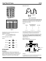
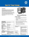
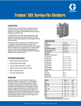
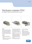
In a Maxi-Flo system the divider valves operate in a sequential
manner (See Figure 1). Figure 2 illustrates a typical system.
Refer to engineering slide card No. 412-C.
SECONDARY
DIVIDER VALVES
LARGE BEARINGS
Figure 2 Typical Maxi-Flo System
Figure 1
The divider valve is self-cycling and no reverser is required. It
is made up of 3 or more intermediate sections which contain
metering pistons. The pistons move progressively back and forth.
There is a number and a letter stamped on each intermediate
section of the divider valve. The number is the output (for each
position stroke) of that intermediate section per cycle of the
divider valve in thousandths of a cubic inch., The S or T indicates
single or twin outlets. An S intermediate section is designed to
discharge oil to only one point. The T intermediate section, or
twin, discharges oil to two points.
Singling and crossporting can be accomplished internally
(intermediate sections can be ordered as singles or twins), or with
an external singling or crossporting bar.
L23110
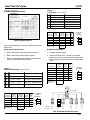
Trabon® Maxi-Flo® System
Relative Size of A to B
A
B
3
2
A = 3 = 1.5 to 1
B 2
Figure 4 The Basic Ratio
MJ Divider Valve
Volume (in3)
Per Outlet
Size
5T
10T
.005
5S
.010
15T
.015
10S
.020
15S
.030
T = Two Outlets
To obtain the basic ratios of a group of bearings, divide the lubricant
requirements of each bearing by the smallest oil requirements of the
group. (Refer to calculating lube requirements, Trabon Application
Engineering Lit. No. L20115.)
Example:
Bearing
Unit of Oil Required in a
Given Time Period
Basic Ratio
A
2
1
B
3
1.5
C
4
2
A = 2/2 =1
B = 3/2 = 1.5
C = 4/2 = 2
S = One Outlet
Figure 3
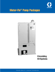
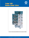
Crossporting joins two adjacent intermediate sections, thus
combining their capacities.
This illustration shows both the relative and actual quantity of oil
discharged during one complete cycle of the divider valve.
Example: 15 S & 15 S yields .060 cu.in./cycle
10 S & 10 S yields .040 cu.in./cycle
It can be seen in Figure 5 that the total oil discharged by the divider
valve during one cycle is .080 cubic inches. Conversely, if .080
cubic inches of oil is supplied to the inlet of this divider valve it will
complete one cycle.
A wide range of ratios are available.
Example:
(One cycle equals Ts x 2)
(Where Ts = total of intermediate section sizes)
5T & 15S
0.030
0.005
= 1:6
10T & 15S
0.030
0.010
= 1:3
10T & 15T
0.015
0.010
= 1:1.5
15S Sections
0.060
0.005
= 1:12
Lubricant .080
1
2
3
4
Inlet
5T
10T
15S
10S
End
5
6
7
8
.005 .010 .020
1 Cycle
.030 .010
.005
Relative
Amounts
SYSTEM DESIGN
Proportioning—
The proportioning of oil in a Maxi-Flo system depends on the
relative size of the pistons in a divider valve. Therefore, to size the
pistons correctly one need only know the relative size of the oil
requirements. This relative size is called "The Basic Ratio."
1
2
4
Ratio
Actual Cu. In.
6
2
1
Figure 5 Proportioning
Examples:
By multiplying the basic ration by the smallest intermediate section
capacity (5) the actual section size can be determined.
Page 2
L23110
Trabon® Maxi-Flo® System
'&%$#"!
+&*#!"%)#("
0%-/.-%)&,
'&%$#"!
3 &2 1
0.16"154$1
+&*#!"
8(-.7&
0.16"154$1
=&& <()& ;:9
'%*#/
3%)#(
'%*#/
3%)#(
?>
!
$##"
$#%#
%$#
&
'
$##&
$#%#
%$#
&
(
$#)#
$#)#
)$#
"#
*
$#"#
$#"#
"$#
%#
+
$#"#
$#"#
"$#
%#
,
$##"
$#%#
%$#
&
-
$#%#
$#%#
%$#
&
76543 *210/.
>63<=2 (<$;.$:98$
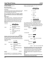
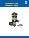
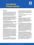
The design procedure for a Maxi-Flo centralized lubrication system
is as follows:
“MJ” Divider
Valve
Assembly
A
F
D
B
G
E
5T
5T
10T
10S
C
$%"#
1. Survey machine (See Figure 6 machine survey) and group
bearings
2. Determine type of Maxi-Flo pump best suited for the
application • Time Controlled
• Stroke Controlled
• Remote Controlled (Refer to Graco Product Specs
and Ordering Lit.)
3. Calculate bearing requirements (Refer to Lit No. L20115)
Note: In systems where central pressure signaling is
desired the following is recommended:
4. Design secondary divider valve assemblies
If the oil to be used in the system is less than 2000 SUS
(actual), substitute .010 cubic inches per hour (design
volume) for all bearings where the calculated volume is less
than .010 cubic inches per hour. If using oil above 2000
SUS (actual), substitute .005 cubic inches per hour (design
volume) for all bearings where the calculated volume is less
than .005 cubic inches per hour. Oils with viscosities less
than 300 SUS (actual) are not recommended.
6. Determine total system oil requirement in cubic inches per
hour
5. Design master divider valve assembly
DESIGN PROBLEM
MJ Divider Valves are to be used with a .001 cu.in/hour oil film
replacement rate. A SAE 30wt oil is to be used in the system, and
a central pressure signal is desired. The Maxi-Flo time control unit
has been selected to supply the system.
When a whole number cannot be obtained, use the next higher
whole number. In this case the 18.5 ratio requirement will be a
10 S size intermediate section, thus providing .020 cubic inches
per cycle.
The machine contains 25 lubrication points which have been
grouped. Lube volumes have been assigned to groups 3—6.
(See Figure 6 machine survey). Groups 1 and 2 are contained on
machine bearing list Figure 6, and will be used as the example for
designing the divider valves.
DESIGNING A MAXI-FLO SYSTEM
'&%$#"!
+&*#!"%)#("
0%-/.-%)&,
'&%$#"!
3 &2 1
0.16"154$1
+&*#!"
8(-.7&
0.16"154$1
=&& <()& ;:9
!
$#""
$#""
%
#"
&
$#('
$#('
*$)
+($'
,
$"'"
$"'"
#
'
-
$"'"
$"'"
#
'
.
$#""
$#""
%
#"
87654 -3210/
?74=>3 ,=$</$;:9$
'%*#/
3%)#(
'%*#/
3%)#(
?>
“MJ” Divider
Valve
Assembly
A
B
C
10T
10S
5T
E
D
U
T
A B
C D
$#%"
S
R
A B
C D
J K
L M
N
J K
L M
P
NQ
P
Typical Machine
S
R
O
U
T
V
O
W
X
V
Q
X
Y
W
Y
Typical Machine
'&%$#"!
+&*#!"%)#("
0%-/.-%)&,
'&%$#"!
3 &2 1
0.16"154$1
+&*#!"
8(-.7&
0.16"154$1
=&& <()& ;:9
'%*#/
3%)#(
'%*#/
3%)#(
?>
!
$"#"
$"#"
%
&
'
$"%"
$"%"
#
("
)
$"*"
$"*"
+
(&
,
$"#"
$"#"
(
&
65432 ,10/.=52;<1 );$:-$987$
Page 3
$(%"
Letter - Bearing Location
“MJ” Divider
Valve
Assembly
A
B
Letter - Bearing Location
5S
5S
5T
10T D
Group
10S Group Design1Volume
Design
15S
CVolumeCu.In./Hr.
Cu.In./Hr.
.052
5S5T
5S5S
5T10S
10S
1
.052
2
.112
5T 15S
5S 5T
10S 5S
10S
2
.112
3
.206
15S
5T
5S
3
.206
15T 15T
10S 10S
5S 5S
4
4
.100
.100
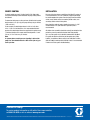
Figure 6 Machine Survey
5S5S
5S5S
5T5T
5
5
.052
.052
15S
15S
15T
15T
10S
10S
6
6
.104
.104
L23110
Trabon® Maxi-Flo® System
DESIGN PROBLEM (Continued)
Group 2 —
Plain Bearings — Vol = π DL x T*
Brg.
Dia. x L x
= Area
A x T* = Vol./Hr
E
3 X 4 X 3.14 = 38.0 In.
38.0 x .001 = .038 Cu. In./Hr.
F
3x4x
3.14 = 38.0 In.
38.0 x .001 = .038 Cu. In./Hr.
G
2 x 2.5 x 3.14 = 16.0 In.
16.0 x .001 = .016 Cu. In./Hr.
H
1x2x
3.14 = 6.0 In.
6.0 x .001 = .006 Cu. In./Hr.
I
1x2x
3.14 = 6.0 In.
6.0 x .001 = .006 Cu. In./Hr.
*T = .001 cubic inches/hour oil film replacement rate.
Figure 7 Machine Bearing List
Given the above information, the next step is to design the secondary
divider valves.
' &%$#"!
+ &*#!"%)#("
0 %-/.-%)&,
' &%$#"!
3 &2 1
0 .16"154 $1
+ &*#!"
8(-.7&
0 .16"154 $1
=&& < ()& ;:9
' %*#/
3 %)#(
' %*#/
3 %)#(
?>
!
%$#"
%$#"
#%"
'&
(
$#"
%$#"
#%"
'&
)
%$'*
%$'*
'%*
"
+
%$$*
%$'$
'
,
-
%$$*
%$'$
'
,
87654 3 210 /.
>74;=2 < ;% -.%:+9%
“MJ” Divider
Valve
Assembly
H
I
G
5T
5S
10S
10S
E
F
%''?
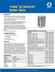
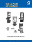
Design Secondary Divider Valves —
Design Master Divider Valve —
1. Group 1 illustrates four single roller bearings (See Figure 7).
1. List design volume for groups
2. Group 2 illustrates five plain bearings (See Figure 7).
2. Design master divider valve — consider each secondary
divider valve as a point, with the total design volume required
equal to the total of all points served by the secondary divider
valves.
3. Group 3 thru 6 are not detailed; however total design volumes
(cu.in./hr.) and MJ divider valves are shown.
Group 1 —
Single row roller bearings — Vol = D2R x T*
Brg.
Dia.2 x Rows = Area
A x T* = Vol./Hr
A
(4) X 1 = 16 In2
16 X .001 = .016 Cu. In./Hr.
B
(4) x 1 = 16 In2
16 x .001 = .016 Cu. In./Hr.
C
(3) x 1 = 9 In2
9 x .001 = .009 Cu. In./Hr.
D
(3) x 1 = 9 In2
9 x .001 = .009 Cu. In./Hr.
'&"%$ #"!
-,+*)(
0"/%.,
4%!3(!21&!
76+*5
968*"
76+*5
968*"
;:
!
%$#"
!%$
#
"
%!!"
"%!
!$
&
%"$'
(%$
"$
(
%!$$
!%)
!$
#
%$#"
!%$
#
*
%!$(
"%$
!$
54321 0/.-,+
=41:</ ;:% 9+%876%
A// @43/ ?">
Master
“MJ” Divider
5
2
6
5T
1
4
3
10T
10S
5S
%*"'
*T = .001 cubic inches/hour oil film replacement rate.
Pump
.63 cu. in./hr.
'&%$#"!
+&*#!"%)#("
0%-/.-%)&,
'&%$#"!
3 &2 1
0.16"154$1
+&*#!"
8(-.7&
0.16"154$1
=&& <()& ;:9
'%*#/
3%)#(
'%*#/
3%)#(
?>
!
%$#"
%$#"
#%"
&%$
'
%$#"
%$#"
#%"
&%$
(
%$$)
%$#$
#
*
+
%$$)
%$#$
#
*
54321 +0/.-,
<41:;0 (:% 9,%876%
%$*=
5T
10T
10S
5S
“MJ” Divider
Valve
Assembly
A
C
5S
5S
5T
B
D
5S
5S
5T
Group
#1
Cu. in./hr. .052
5T
5S
10S
10S
#2
.112
15S
5T
5S
#3
.208
15S
15T
10S
#6
.104
5S
5S
5T
15T
10S
5S
#4
#5
.100
.052
Note: Do not third state Maxi-Flo systems
Page 4
L23110
Trabon® Maxi-Flo® System
DESIGN PROBLEM (Continued)
operation. To determine the proper stroke setting, use Formula #1,
as above and proceed as follows:
(0.06) x (SPM) x (B)
Maxi-Flo Pump Settings —
(For units having 115 V 60 Hz service only)
Time Control —
The time control unit Part No. 563379 (521-500-910) was selected
to supply the example system, therefore set the Solid State Timer
for "on" time required. See Lit. No. L13110.
Dv
Solve for B
A = 8.33 x Dv
= 8.33 x 2.77
= 23.07
Note: In systems where central pressure signaling is required
the pump should not be set for less than .120 cubic inches per
hour.
Stroke Control —
If stroke control unit Part No. – (521-500-420) is selected to supply
system, first determine electrical connections to machine cycle
control. Second, determine the average machine cycles per min.
(SPM). Third, determine the system design volume per hr. (Dv).
Fourth, using the following formula, calculate the pump stroke
setting (Ssc).
Formula #1
(*0.06) x (SPM) x (B)
Ssc =
Where:
Dv
Ssc =
Calculated stroke setting for
pump counter
SPM =
Average machine strokes per
minute
Dv =
System design volume, cubic
inches per hour
A = *8.33 x Dv
*Constants
Should the calculated stroke setting fall between stroke increments
of the pump counter, it is necessary to calculate the actual output
delivered at both the higher and lower stroke settings and choose
the appropriate setting. Use the following formula to determine the
outputs at both settings.
Formula #1
(*3.6) x (SPM)
Where:
Output =
SPM =
Ssa + C
Actual pump output, cubic
inches per hour
Average machine strokes per
minute
Actual stroke setting for pump
Ssa =
counter
C = (*0.5) x (SPM)
Example:
*Constants
A machine requires 2.77 cu.in. of lubricant per hr. to satisfy the
lube system. The machine averages 30 strokes per min. when in
Page 5
= 60 - 23.07
= 36.93
(0.06) x (30) x (36.93)
Ssc =
2.77
24 Required stroke setting to
satisfy system requirements
The calculated stroke setting of 24 is between the 16 and 32
settings on the stroke counter. Therefore, outputs at the 16 and 32
stroke settings must be calculated to determine which setting would
be more appropriate to use. Outputs can be determined by using
Formula #2, as follows:
3.6 x SPM
Output (cu.in.) =
Ssa + C
Ssc =
Solve for C
C = 0.5 x SPM
= 0.5 x 30
= 15
32 Stroke Setting
B = *60 - A
Output (cu.in) =
B = 60 - A
Output (cu.in.) =
3.6 x 30
32 + 15
Output (cu.in.) =
180
47
Output =
2.298 cu.in./hr @ 32 strokes
setting
16 Stroke Setting
Output (cu.in.) =
3.6 x 30
16 + 15
Output (cu.in.) =
180
31
Output = 3.484 cu.in./hr @ 16 stroke setting
The lube system requirement was 2.77 Cu.In./Hr. If the 32 stroke
setting were selected (2.298 Cu.In./Hr.), the system would receive
17% less lubrication than required. If the 16 stroke setting was
selected (3.484 Cu.In./Hr.). the system would receive 26% more
lubrication than required. A decision can now be made s to
which stroke setting would be more appropriate for the particular
application.
Note:
The pump volume can be increased by lowering stroke settings
and decreased by increasing stroke setting.
REMOTE CONTROL
INSTALLATION
If remote control pump unit, Part No. 563376 (521-500-430) is
selected the following recommendations for pump setting should
be followed:
Because of the low volume capabilities of the Maxi-Flo system, it
is recommended that 1/8" O.D. (.020 wall) copper/nylon tubing
be used throughout the system, from the pump to master divider
valves, master divider valves to secondary divider valves, and
secondary divider valves to lube points.
To determine total pump run time per hour, divide the total system
design volume (cu.in. pr hr.) by the pump delivery rate per minute
(.120 cu.in./min.).
In the example, the total design volume is .628 cu.in./hr. thus,
.628 ÷ .120 = 5.22 minutes/hour. It is recommended that one
quarter of the total design volume be supplied to the system every
15 minutes therefore, the remote control should provide 1.3 min.
(78 sec.) of "on" time every 15 minutes.
Note:
In systems where central pressure signaling is desired the
pump "on" time should not be less than .5 min. (30 sec.) per
each cycle time.
Hose should be used only when absolutely necessary. A 3/16"
inside diameter L.V.E. (low volumetric expansion) hose is
recommended.
All divider valve assemblies should be centrally located to the lube
points they serve to provide the shortest feed lines possible.
As in any lube system all air should be removed from the MaxiFlo system for effective oil delivery to lube points (see Lit. No.
L30103). Installation of Graco manual reset indicators Part No. –
(509-931-000) in working outlet of divider valves is recommended
in order to facilitate system troubleshooting.
All written and visual data contained in this document are based on the latest product information available at the time of publication. Graco reserves the right to make changes at any time without notice.
Contact us today!
To receive product information or talk with a Graco representative,
call 800-533-9655 or visit us online at www.graco.com.
©2006-2009 Graco Inc. Form No. L23110 Rev. B 3/09 Printed in U.S.A. All other brand names or marks are used for identification purposes and are trademarks of their respective owners. All written and
visual data contained in this document are based on the latest product information available at the time of publication. Graco reserves the right to make changes at any time without notice.