1
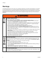
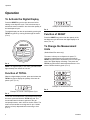
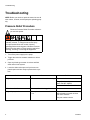
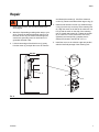
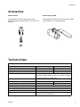
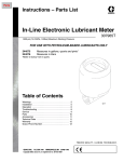
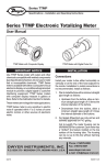
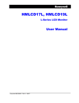
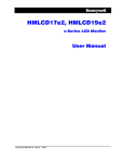
Instructions
In-Line Electronic
Lubricant Meter
For use with petroleum-based lubricants only. For professional use only.
Model 244075
Measures in gallons, quarts and pints*
*Meter is factory set in quarts.
Model 244076
Measures in liters
1500 psi (10.3 MPa, 103 bar) Maximum Working
Pressure
Important Safety Instructions
Read all warnings and instructions in this
manual. Save these instructions.
307965Y
EN
Warnings
Warnings
The following warnings are for the setup, use, grounding, maintenance, and repair of this equipment. The exclamation point symbol alerts you to a general warning and the hazard symbols refer to procedure-specific risks. When
these symbols appear in the body of this manual or on warning labels, refer back to these Warnings. Product-specific
hazard symbols and warnings not covered in this section may appear throughout the body of this manual where
applicable.
WARNING
EQUIPMENT MISUSE HAZARD
Misuse can cause death or serious injury.
• Do not operate the unit when fatigued or under the influence of drugs or alcohol.
• Do not exceed the maximum working pressure or temperature rating of the lowest rated system
component. See Technical Data in all equipment manuals.
• Use fluids and solvents that are compatible with equipment wetted parts. See Technical Data in all
equipment manuals. Read fluid and solvent manufacturer’s warnings. For complete information
about your material, request MSDS from distributor or retailer.
• Do not leave the work area while equipment is energized or under pressure.
• Turn off all equipment and follow the Pressure Relief Procedure when equipment is not in use.
• Check equipment daily. Repair or replace worn or damaged parts immediately with genuine manufacturer’s replacement parts only.
• Do not alter or modify equipment. Alterations or modifications may void agency approvals and create
safety hazards.
• Make sure all equipment is rated and approved for the environment in which you are using it.
• Use equipment only for its intended purpose. Call your distributor for information.
• Route hoses and cables away from traffic areas, sharp edges, moving parts, and hot surfaces.
• Do not kink or over bend hoses or use hoses to pull equipment.
• Keep children and animals away from work area.
• Comply with all applicable safety regulations.
SKIN INJECTION HAZARD
High-pressure fluid from dispensing device, hose leaks, or ruptured components will pierce skin. This
may look like just a cut, but it is a serious injury that can result in amputation. Get immediate surgical
treatment.
• Do not point dispensing device at anyone or at any part of the body.
• Do not put your hand over the fluid outlet.
• Do not stop or deflect leaks with your hand, body, glove, or rag.
• Follow the Pressure Relief Procedure when you stop dispensing and before cleaning, checking, or
servicing equipment.
• Tighten all fluid connections before operating the equipment.
• Check hoses and couplings daily. Replace worn or damaged parts immediately.
CALIFORNIA PROPOSITION 65
This product contains a chemical known to the State of California to cause cancer, birth defects or other
reproductive harm. Wash hands after handling.
2
307965Y
Installation
Installation
These meters must be installed in-line as part of a dispense system as shown in Fig. The typical installation shown is
only a guide for selecting and installing an in-line meter. It is not an actual system design. Contact your Graco representative for assistance in designing a system to suit your needs.
A
B
C
D
E
F
KEY
A In-line meter
B In-line strainer
C Shutoff valve
D Pressure relief valve
E Check valve
F Bleed–off valve
FIG. 1
Key:
A
B
C
D
E
F
In-line meter
In-line strainer
Shutoff valve
Pressure relief valve
Check valve
Bleed-off valve
307965Y
3
Operation
Operation
To Activate the Digital Display
Press the RESET key pad to clear the meter before
starting a new dispense cycle. This is the best way to
activate the meter, because it also clears the quantity of
the last dispense cycle.
The digital display can also be activated by pressing the
TOTAL key pad or by running fluid through the meter.
(FIG. 2)
GAL
Example of Accumulated Total
FIG. 4
Function of RESET
Press the RESET key pad to clear the quantity of the
last dispense cycle and return the digital display to all
zeros. (FIG. 2)
GRACO
GAL
TOTAL
RESET
Press RESET to
clear
FIG. 2
NOTE: The digital display of the meter goes blank after
approximately two minutes of non-use.
To Change the Measurement
Units
(Gallon/Quart/Pint meter only)
The meter is factory set to dispense in quarts. To
change the measurement units, press and hold the
RESET key pad until the measurement unit on the right
side of the digital display is flashing. Then press the
TOTAL key pad until the desired measurement u nit is
shown. Release both key pads. (FIG. 5)
Function of TOTAL
PTS
When the digital display is blank, press and release the
TOTAL key pad to display the quantity of the last dispense cycle. (FIG. 3)
QTS
GAL
QTS
Example of measurement units
FIG. 5
Example of Total for Last Dispense Cycle
FIG. 3
To see the accumulated total of fluid dispensed through
the meter, press and hold the TOTAL key pad. The
accumulated total is shown in gallons for the gallon/quart/pint meter, and in liters for the liter meter. The
meter can accumulate a running total of up to 19,999
gallons (or liters) dispensed before returning to zero.
(FIG. 4)
4
307965Y
Operation
To Verify the Accuracy of an
Electronic Meter
1. Use a clean, calibrated container. If using a single
container, be sure to clean it after each dispense.
2. Have pump air pressure at the lowest possible setting for dispensing fluid.
3. Put the tip of the nozzle at the bottom of the calibrated container.
4. If the tip of the dispense valve does not reach the
bottom of the calibrated container, use a length of
plastic tubing over the tip of the nozzle to ensure liquid enters the container from the bottom.
5. Trigger the gun slowly so the fluid immediately covers the tip of the dispense valve.
6. Allow product to sit for 20 minutes, then compare
the actual, physical measurement in the calibrated
container to the measure displayed on the meter.
NOTE: The procedure above will determine if the meter
is accurately dispensing the product and minimize testing errors. Some variance may occur depending on the
viscosity of the fluid. If this procedure determines that
the meter is not accurate replace the meter or the electronics as necessary.
For Maximum Dispensing
Accuracy
(gallon/quart/pint meter only)
Set the meter to dispense in pints or quarts when dispensing 1 gallon or less.
Always press the RESET key pad to clear the meter
before a new dispense cycle.
307965Y
5
Troubleshooting
Troubleshooting
NOTE: Before you check or repair the meter, be sure all
other valves, controls, and the pump are operating properly.
Pressure Relief Procedure
Follow the Pressure Relief Procedure whenever
you see this symbol.
This equipment stays pressurized until pressure is
manually relieved. To help prevent serious injury
from pressurized fluid, such as skin injection,
splashing fluid and moving parts, follow the Pressure
Relief Procedure when you stop spraying and before
cleaning, checking, or servicing the equipment.
1. Turn off the power supply to the pump.
2. Trigger the valve into a waste container to relieve
pressure.
3. Open any bleed-type master air valves and fluid
drain valves in the system.
4. Leave the drain valve open until you have completed repairs and are ready to pressurize the system.
Problem
Digital display does not activate.
Cause
Electronic control is malfunctioning.
Solution
Replace the electronic control.
For gallons/quarts/pins:
Order Part No. 235878
For Liters: Order Part No. 235901
There is no fluid flow.
Strainer, if used is clogged.
Remove and clean strainer.
Digital display is dim.
Battery in electronic control is worn
out.
Replace electronic control within
approximately one week of when
you notice dimness.
See part numbers above.
6
307965Y
Repair
Repair
and discard the screws (6). Lift off the electronic
control (3). Remove and discard the large o-ring (4).
1. Relieve the pressure. See Pressure Relief Procedure, page 6.
2. Attach the disposable grounding wrist strap to your
wrist. Connect the adhesive-backed copper foil at
the other end to any convenient electrical ground,
such as the grounding screw or metal case of a
grounded electrical outlet.
3. Lift the bottom edge of the black cover (1) away
from the meter (2), and pull the cover off. Remove
4. Install a new electronic control (3). Install the large
o-ring (4) over the lip on the top of the metering unit
(2). Align the notch on the side of the electronic control (3) with the notch on the side of the metering
unit (2). Install new screws (6). Tighten the screws
(6) to 3 in-lbs to 5 in-lbs (0.34 N.m to 0.57 N.m)
oppositely and evenly until a complete seal is
obtained as shown in the DETAIL in FIG. 6.
5. Install the cover so the rolled-in edges are parallel
with the inlet fluid passage of the metering unit.
DETAIL
1
6
6
3
4
4
2
FIG. 6
307965Y
7
Parts
Parts
1
6
3
4
2
Model 224075, Gallon/Quart/Pint
Ref.
1
2
3*
4
6
Part
Description
191782 COVER
METERING UNIT, gallon/quart/pint
235878 ELECTRONIC CONTROL
109137 O-RING
112093 SCREW
*Replacement screws and o-rings included with item 3.
Qty
.
1
1
1
1
6
Model 244076, Liter
Ref.
1
2
3*
4
6
8
Part
Description
191782 COVER
METERING UNIT, liter
235901 ELECTRONIC CONTROL
109137 O-RING
112093 SCREW
Qty
.
1
1
1
1
6
307965Y
Accessories
Accessories
Strainer 223179
Shutoff Valve 108458
Install between the shutoff valve and the meter.
Removes particles from the lubricant. 40 mesh. 1/2 in.
npt (m x f)
Install upstream from the meter. Shuts off fluid supply
from the pump. 1/2-14 npt(f) both ends.
Technical Data
In-Line Electronic Lubricant Meter
US
Maximum fluid working pressure
Flow Range*
Weight
Units of measurement
Inlet and outlet
Operating temperature range
Storage temperature range
Battery Specifications
Rated discharge current
Rated capacity
Maximum continuous discharge current
Wetted Parts
307965Y
1500 psi
0.12 to 12 gpm
1.9 lb
Metric
10.3 MPa, 103 bar
0.456 to 45.6 lpm
0.95 kg
Factory-set in quarts. Display shows quantity in 0.01 increments up to 199.99 gallons, quarts, pints, or liters. Totalizes
in gallons or liters up to 19,999 units.
1/2 npt, non-directional flow
-4°F to 130°F
-2°C to 55°C
-40°F to 140°F
-40°C to 60°C
100 microamps
1.0 amp hour
1.0 milliamp
Aluminum, carbon steel, nitrile rubber, nickel, bronze, stainless steel #304, cast ALNICO 8
9
Graco Electronic Dispense Valve Warranty and
Disclaimers
Graco warrants all equipment manufactured by it and bearing its name to be free from defects in material and workmanship on the date of sale to
the original purchaser for use. As purchaser’s sole remedy for breach of this warrant, Graco will, for a period of twelve months from the date of
sale, repair or replace any part of the equipment proven defective, with the exception of defects in the electronic meter control, including the
battery, which will be repaired or replaced for twenty-four months from the date of sale. This warranty applied only when the equipment is installed,
operated and maintained in accordance with Graco’s written recommendations.
This warranty does not cover, and Graco shall not be liable for, any malfunction, damage or wear caused by faulty installation, misapplication,
abrasion, corrosion, inadequate or improper maintenance, negligence, accident, tampering, or substitution of non-Graco component parts. Nor
shall Graco be liable for malfunction, damage or wear caused by the incompatibility with Graco equipment of structures, accessories, equipment
or materials not supplied by Graco, or the improper design, manufacture, installation, operation or maintenance of structures, accessories,
equipment or materials not supplied by Graco.
This warranty is conditioned upon the prepaid return of the equipment claimed to be defective to an authorized Graco distributor for verification of
the claim. If the claimed defect is verified, Graco will repair or replace free of charge any defective parts. The equipment will be returned to the
original purchaser transportation prepaid. If inspection of the equipment does not disclose any defect in material or workmanship, repairs will be
made at a reasonable charge, which charges may include the costs of parts, labor and transportation.
Disclaimers and Limitations. The terms of this warranty constitute purchaser’s sole and exclusive remedy and are in lieu of any other warranties
(express or implied), including warranty of merchantability or warranty of fitness for a particular purpose, and of any non-contractual liabilities,
including product liabilities, based on negligence or strict liability. Every form of liability for direct, special or consequential damages or loss is
expressly excluded and denied. In no case shall Graco’s liability exceed the amount of the purchase price. Any action for breach of warranty must
be brought within two (2) years of the date of sale.
Equipment not covered by Graco Warranty. Graco makes no warranty, and disclaims all implied warranties of merchantability and fitness for a
particular purpose, with respect to accessories, equipment, materials, or components sold but not manufactured by Graco. These items sold, but
not manufactured by Graco (such as electric motor, switches, hose, etc.) are subject to the warranty, if any, of their manufacturer. Graco will
provide purchaser with reasonable assistance in making any claim for breach of these warranties.
FOR GRACO CANADA CUSTOMERS
The Parties acknowledge that they have required that the present document, as well as all documents, notices and legal proceedings entered into,
given or instituted pursuant hereto or relating directly or indirectly hereto, be drawn up in English. Les parties reconnaissent avoir convenu que la
rédaction du présente document sera en Anglais, ainsi que tous documents, avis et procédures judiciaires exécutés, donnés ou intentés, à la suite
de ou en rapport, directement ou indirectement, avec les procédures concernées.
Graco Information
For the latest information about Graco products, visit www.graco.com.
TO PLACE AN ORDER, contact your Graco distributor or call to identify the nearest distributor.
Phone: 612-623-6928 or Toll Free: 1-800-533-9655, Fax: 612-378-3590.
All written and visual data contained in this document reflects the latest product information available at the time of publication.
Graco reserves the right to make changes at any time without notice.
For patent information, see www.graco.com/patents.
Original instructions. This manual contains English. MM 307965
Graco Headquarters: Minneapolis
International Offices: Belgium, China, Japan, Korea
GRACO INC. AND SUBSIDIARIES • P.O. BOX 1441 • MINNEAPOLIS MN 55440-1441 • USA
Copyright 1988, Graco Inc. All Graco manufacturing locations are registered to ISO 9001.
www.graco.com
Revised December 2014