1
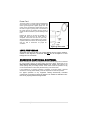
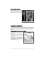
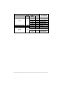
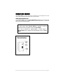
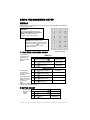
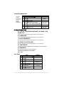
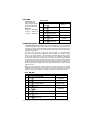
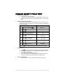
3 WIDE COMBI STAND ALONE COLD/FROZEN FOOD VENDOR (GVC2 Controller) MODELS: 3532M/3532MA – MULT-ZONE (Cold and Frozen Food) 3532F/3532FA – SINGLE-ZONE (Frozen Food) 3532C/3532CA – SINGLE-ZONE (Cold Food) SERVICE MANUAL DEC 2009 4218450•A Table of Contents INTRODUCTION ............................ 1 TEMPERATURE CONTROL ......... 22 SPECIFICATIONS .......................... 2 HEALTH SAFETY FIELD TEST .... 25 UNPACKING .................................. 3 REFRIGERATION......................... 26 LOADING PRODUCTS ................... 5 REMOVING THE REFRIGERATION SYSTEM....................................... 30 TRAY ADJUSTMENTS................... 7 AUGER TIMING ............................. 9 CONTROLLER FUNCTIONS ........ 10 SERVICE MODE........................... 11 BASIC PROGRAMMING SETUP .. 12 REFRIGERATION CONFIGURATION SETTINGS ..... 16 PRICING ...................................... 17 PREVENTIVE MAINTENANCE..... 30 CONVERTING FROM SINGLE ZONE TO MULTI-ZONE MODE .... 31 CONVERTING FROM MULTI-ZONE MODE TO SINGLE ZONE ............. 31 REPLACE AIR FILTER ................. 32 PARTS ORDERING PROCEDURE 34 BEFORE CALLING FOR SERVICE34 ADVANCED OPTIONS ................. 18 TEST ALL MOTORS..................... 19 If you have any questions pertaining to information in the manual, replacement parts or the operation of the vendor, then you should contact your local distributor or: Please have the model and serial numbers if you need service and parts information. The numbers are on the identification plate located on the back side of the cabinet of the vending machine. SERIAL NUMBER: ii VendNet 165 North 10th Street Waukee, Iowa 50263 Phone: (888) 259-9965 Parts Fax: (515) 274-5775 Sales Fax: (515) 274-0390 E-mail: [email protected] ___________________________________ COMBI VENDOR • 3532 • 4218450 INTRODUCTION This manual contains instructions, service and installation guidelines for the 3W COMBI Vendor. Please read this manual thoroughly and follow instructions. The initial set-up of a vending machine is a very important step of insuring that the equipment operates in a trouble-free manner. The 3W COMBI Vendor can be factory configured to have two temperature compartments (top and bottom) in a single vending machine separated by moveable air deflectors and insulating barrier. The vending machine has an air duct that runs up and down on the back inner wall of the cabinet. Each compartment can have 3 moveable trays and a total of 6 trays for the entire vending machine. The vending machine will maintain 2°C (36°F) in the Top compartment and down to 24°C (-12°F) in the bottom compartment at an ambient range of 4.4°C-32°C (40°F-90°F). The temperature setting for both compartments are set by the controller (program). TOP BOTTOM The top compartment has a heater system to maintain constant temperature across varying ambient temperatures. This consists of a heater, temperature sensor, air circulating blower and relays The bottom compartment has a temperature sensor and an insulated refrigeration system. Cool air is drawn from the refrigeration system’s evaporator coils through the air duct and is deflected into the bottom zone by a moveable air deflector. There are openings in the bottom trays to allow air to circulate around the products. All programming of the pricing, vend functions and features are also done at the controller. Changes can be made without any additional accessories or remote parts. Selections can be priced individually from $00.00 to $655.35 in five cent increments (US currency). Cash accountability records, total cash transactions, total vend cycles performed by the vendor, information for individual selections, complete rows or total machine can be compiled and used for inventory and ordering records. Electrical malfunctions are recorded and displayed when the vending machine is placed in the Service Mode. Non-functional motors or selections are indicated. Each selection has an individual motor. Functional selections will continue to operate if other motors become nonfunctional. The vending sequence is "first-in, first-out" for each selection, permitting stock rotation to maintain fresh products in the vending area. Each 3W COMBI Vendor has the capability of supporting a "satellite" vending machine, such as a direct wire CB300-SAT, or a USD satellite such as a CF1000. The satellite vendor utilizes the 3W COMBI Vendor’s existing controller, coin mechanism, bill validator and keypad to perform the vend functions they require. For details on the satellite vendor, refer to the Service Manual pertaining to the specific vendor for installation instructions. COMBI VENDOR • 3532 | 1 SPECIFICATIONS DIMENSIONS & WEIGHT TYPE MULTI-ZONE (3 WIDE) MODEL 3532 WIDTH 3532A 29.5 in. (74.9 cm) DEPTH 38 in. (96.5 cm) HEIGHT 72 in. (182.9 cm) 1 693 lbs (614 kg) EST. SHIPPING WT.1 722 lbs (327 kg) ESTIMATED WEIGHT Note: 1 Weights will vary depending on optional equipment installed. ELECTRICAL MODEL Danfoss 5/8 Hp VOLTAGE 115 VAC 230 VAC 60 Hz 50 Hz 9.0 Amps 4.5 Amps 110/24 VAC 230/24 VAC CYCLE NOMINAL AMPS TRANSFORMER REFRIGERATION HORSEPOWER TYPE Danfoss 5/8 Hp Hermetically Sealed CONTROLS Electronic REFRIGERANT R-404a CHARGE 17 oz COIN CHANGER, BILL VALIDATOR, CARD READER TYPE MDB Coin Changer level II or III, Bill Validator Level I, Card Reader Level I or II VENDOR OPERATION LOCATION RECOMMENDED OPERATING TEMPERATURE COMBI VENDOR • 3532 | 2 Suitable for indoor use only Between 40° and 90° Fahrenheit (4° and 32° Celsius) UNPACKING This vending machine was thoroughly inspected before leaving the factory and the delivering carrier has accepted this vendor as their responsibility. Note any damage or irregularities at the time of delivery and report them to the carrier. Request a written inspection report from the claims inspector to file any claim for damage. File the claim with the carrier (not the manufacturer) within 15 days after receipt of the vending machine. Carefully remove the outside packing material so as not to damage the finish or exterior of the vending machine. Inspect the vending machine for concealed shipping damage. Report any damage hidden by the shipping material directly to the delivering carrier on a hidden damage report. Record the model number and serial number of the vendor for your records. These numbers can be found on the Serial Plate on the rear of the cabinet and/or inside the vendor. Refer to these numbers on all correspondence and inquiries pertaining to this vendor. Remove the shipping skids by placing a 2x6 under the vendor, inserting a large screwdriver or prying tool into the grove and splitting it in two. Turn the leveling screws in as far as possible. See Figure 3a. Figure 3a. Remove Shipping Skids INSTALLATION • • • Consult local, state and federal codes and regulations before installing the vendor. Retrieve the keys to the vendor from the coin return cup. Open outer door and remove all internal packing material. COMBI VENDOR • 3532 | 3 Power Cord The power cord is a 14 gauge cord and is fastened to rear mounting box so it stays with the machine and doesn’t get changed with a lighter gauge cord. The power cord is connected and routed under the cover as shown in Figure 4g. Keep power cord secured on the center back of the cabinet until the vendor is placed into its final location to prevent damage to the cord. Position the vendor in its place of operation no further than nine feet from the power outlet or receptacle. Check that the door will open fully without interference. Leave at least four (6”) inches of space between the back of the vending machine and any wall or obstruction for proper air circulation. Figure 4g. Power Cord LEVEL THE VENDOR All levelers must touch the floor. The vendor must be level for proper operation, cabinet to door alignment, condensate drainage, and for acceptance of coins through the coin mechanism. GROUNDING (EARTHING) & ELECTRICAL Before connecting the vendor, the integrity of the main electrical supply must be checked for correct polarity, presence of ground (earth) and correct voltage. Please refer to the Safety Manual and Installation Guidelines Manual (P/N 4206816) that shipped in the service package with your vending machine. These checks should be repeated at six (6) month intervals with the routine safety electrical testing of the vendor itself. If the receptacle is not properly grounded or polarized, you should contact a licensed electrician to correctly polarize and/or ground the receptacle to ensure safe operation. For proper operation of any equipment utilizing electronically controlled components, the equipment should be placed on an isolated or dedicated noisefree circuit, properly polarized and grounded. COMBI VENDOR • 3532 | 4 MAIN POWER SWITCH Plug the power cord to a dedicated power outlet. Open the vendor door. Turn on the main power switch located on the center right hand side of the vendor. See Figure 4h. Figure 4h. Power Panel LOADING PRODUCTS Load product from front to back making sure all items fit freely between the auger spaces. Do not attempt to force oversize items or packages into the spaces. Do not skip a space. Place the product on the bottom of the compartment on the product augers with the label facing the front of the vending machine for easy identification by the customer. See Figure 5a. SNACK/CANDY/FOOD TRAY OPTION To load products, lift the tray slightly and pull forward until the tray stops. The trays tilt for easier loading. The size of the item being vended must be larger than the diameter of the auger being used to vend properly. Undersize items could cause vend problems. If the product does not fit the auger properly, use a different pitched auger. See Error! Reference source not found. for augers available from your distributor or service entity. Figure 5a. Loading Products COMBI VENDOR • 3532 | 5 PRODUCT WIDTH (INCH) TYPE CANDY 2.75 CAN/BOTTLE DISPENSER (12 OZ CAN) 2.75 4.84 SNACK 5.50 COMBI VENDOR • 3532 | 6 THICK (INCH) 0.50 0.66 0.94 1.19 1.50 2.03 3.09 3.09 2.59 DIA 1.19 1.50 1.81 2.62 2.69 QTY 30 24 18 15 12 9 6 6 8 15 12 10 8 7 PART NUMBER 4200272.103309 4200272.102309 4200272.101309 4200272.100309 4200272.104309 4200272.105309 4200272.106309 4200272.106309 4214090 4200272.109309 4200272.108309 4200272.107309 4200272.111309 4200272.110309 TRAY ADJUSTMENTS By re-timing the augers, difficult-to-vend items can be dispensed more dependably. By altering tray spacing, larger items can be vended. By changing the tray configuration, different product mixes can be accommodated. VERTICAL SPACING The trays can be adjusted up or down in half-inch increments to provide additional headroom for vending taller products. When increasing the height in one area, the same amount of room will be lost at the tray above or below the one being adjusted. 3 WIDE SNACK/CANDY/FOOD TRAY 1. Pull out the tray to be adjusted until it stops. 2. Disengage the tray harness from its harness retainer on the right side wall. See Figure 6a on page 8. Disconnect the tray plug from its receptacle on the right side wall. 3. Lift up on the rear of the tray and remove it from the vendor. 4. Disengage both left and right tray rails from their corresponding slots on the left and right side walls by removing two screws holding each rail in place. 5. Relocate both left and right rails by reversing step 4. Rails must be level from front to back and evenly spaced from top to bottom of each side. 6. Replace the tray by placing its rear rollers on the left and right rails and lifting up on the front of the tray as it is pressed back. 7. Install the tray plug into its receptacle on right side wall. 8. Re-engage the tray harness into its harness retainer. See Figure 6a. 9. Test vend the tray in its new position to assure that the tray plug is properly seated. COMBI VENDOR • 3532 | 7 3 WIDE SNACK/CANDY/FOOD TRAY 1. 2. 3. 4. 5. 6. 7. 8. 9. 10. 11. 12. 13. 14. Pull the tray out until it stops. Locate the harness retainer on the right sidewall. See Figure 6a. Pull the tray harness out of the harness retainer. Unplug the tray plug from its receptacle on the right side wall. Lift up on the front of the tray and pull slightly (approximately 1.5 cm (.5 in) forward to clear the tray stop. Locate the release lever on the left and right tray rails. See Figure 6b. Swing the Figure 6a. Tray Harness release levers all the way up to unlatch. Lift up on the rear of the tray and remove it from the vendor. Relocate both left and right tray rails from the left and right side walls. Remove tray rail mounting screws. Pull each rail forward to disengage its rear tab from the hole in the rear wall. See Figure 6b. Relocate both left and right rails by reversing step 7. Rails must be level front to back and left to right. Replace the tray by placing its rear rollers on the left and right rails and lifting up Figure 6b. Tray Rails on the front of the tray as you push it back Swing the tray rail release levers all the way down. Install the tray plug into its receptacle on the right side wall. Re-engage the tray harness into its harness retainer. 15. Test vend the tray in its new position to assure that the tray plug is properly seated. COMBI VENDOR • 3532 | 8 AUGER TIMING SNACK/CANDY/FOOD TRAY Each auger can be rotated in 20° (degree) increments for a different product vend drop-off point. Most items can be vended successfully when the auger end is positioned at 6 o'clock. The general rule is - the narrower the product, then the higher the timing. • Thick Products - 4-6 o’clock • Most products – 6 o’clock • Thin Products - 6-8 o’clock TO CHANGE AUGER TIMING 1. Remove the motor cover. See Figure 6f. 2. Raise the motor slightly and pull forward on the auger until it separates from the motor. 3. Rotate the auger to the desired position and re-insert the hub (auger coupling) into the motor. The hub (auger coupling) must be seated over the vertical rail or retaining rib Figure 6f. Motor & Auger on the tray. (Standard Tray) 4. Replace the motor cover making sure it is securely tightened. Figure 6g. Motor & Auger 5. Test vend to make sure product vends (Can/Bottle Tray) correctly. CAN/BOTTLE TRAY OPTION 1. Remove the hitch pin. See Figure 6g. 2. Pull hub and auger away from the motor. 3. Rotate the hub and auger. 4. Re-insert the hub and auger. 5. Re-insert the hitch pin. 6. Test vend to make sure product vends correctly. COMBI VENDOR • 3532 | 9 CONTROLLER FUNCTIONS IVEND™ CYCLE All vendor selections have been assigned at the factory to be monitored for iVend™ optical sensing. For 5 milliseconds at the start of a vend, the iVend™ optical sensor will be checked to make sure it is not blocked, damaged or disconnected. If blocked, damaged or disconnected - the normal home-switch-vend cycle will be used and the optical sensors will be ignored. Both the vend motor and a vend timeout timer are started. • The selection motor rotates to the home-switch position. • If there is a home-switch signal, then the vend is considered successful. • If after 10 seconds there is no home-switch signal, the vend failed. The vend motor is shut down and MAKE ALTERNATE SELECTION is displayed. The customer can press selection buttons to activate another motor or press the coin return button. If not blocked, damaged or disconnected - the iVend™ Sensor System is used. The vend motor and a vend timeout timer are started. • The selection motor rotates to the home-switch position. • If a product is detected during this time period, then the vend is considered successful. • If after reaching the home-switch position and a product is not detected, then the vend motor will pause for 1 second while the controller continues to monitor the optical sensor for product delivery. o If a product is detected during this pause, then the vend is considered successful. o If a product is not detected, then the controller initiates a second vend cycle and another vend timeout timer while continuing to monitor the optical sensor. If a product is detected during this second cycle, the motor will be stopped immediately. The vend is considered successful. The 2ND VEND accounting counter is increased by one. If after reaching the home-switch position and a product is not detected, then the vend motor is stopped and for 2 seconds the controller continues to monitor the optical sensor for product delivery. If a product is detected, the vend is considered successful. The 2ND VEND accounting counter is increased by one. Otherwise, if no product is detected, the selection is sold out. Such a state will trigger the display of the MAKE ALTERNATE SELECTION message. The amount of credit is displayed. The customer can press selection buttons to activate this or another motor or press the coin return button. o If after 10 seconds there is no home-switch signal and no product is detected, then the vend failed. The vend motor is shut down and MAKE ALTERNATE SELECTION is displayed. The customer can press selection buttons to activate another motor or press the coin return button. NOTE: Force Vend is disabled to permit customer to retrieve deposited money. COMBI VENDOR • 3532 | 10 SERVICE MODE Use Service Mode to program and service the machine. Use the keypad as an input device. Watch the display for information while in Service Mode. SERVICE MODE BUTTON To enter Service Mode, press the Service Mode Button located on the top or upper right corner of the controller cover. See Error! Reference source not found.. To exit Service Mode, press the Service Mode Button. NOTES If credit exists when Service Mode is entered, it will be restored when the machine returns to Sales Mode. If no key is pressed for approximately 1 minute while in Service Mode, the controller will automatically return to Sales Mode. Figure 2.A Controller— Inside Door Mounted COMBI VENDOR • 3532 | 11 BASIC PROGRAMMING SETUP KEYPAD Use the buttons on the keypad as directed in the step-by-step instructions in this manual in programming the vendor. DISPLAY Check the display after pressing the Service Mode Button and/or Keypad Buttons to make sure that the program is responding correctly. Buttons 0-9 are used to move between the various modes, menus and sub-menus; while the button is used to enter a menu, confirm or save a setting. See Figure 3 Figure 3: Keypad 1 TUBE FILL/ DISPENSE COINS Tube Fill counts coins as they are deposited and Shows the dollar amount. STEP 1. 2. 3. TUBE FILL DISPLAY Motor Count 60 Press Service Mode Button Press and begin depositing coins Press 2 times to exit At least 15 of each denomination (Sales Mode) TUBE DISPENSE Tube Dispense 1. Press to dispense dollar coin $1.00/coins Pays out coins from the coin mech coin tubes. 2. Press to dispense quarters 0.25/coins 3. Press to dispense dimes 0.10/coins This mode will also 4. Press to dispense nickels 0.05/coins display the current quantity of coins in 5. (Sales Mode) the coin mech Press 2 times to exit tubes. **Note: For dispensing more than a 4 denomination coin mech. use keys greater in the same sequence as shown above.** 2 MOTOR COUNT Displays the total count of working motors. DISPLAY Press Service Mode Button Motors ( - - ) 2. Press then wait. Motors ( - - ) Press to exit. 3. COMBI VENDOR • 3532 STEP 1. | 12 (Sales Mode) 3 OPTIONS 3.1 FORCE VEND See GVC2 Programming Manual (P/N 4215507) for more information. 3.2 BILL ESCROW See GVC2 Programming Manual (P/N 4215507) for more information. 3.3 MULTI VEND See GVC2 Programming Manual (P/N 4215507) for more information. 3.4 FREE VEND See GVC2 Programming Manual (P/N 4215507) for more information. 3.5 FAST CHANGE See GVC2 Programming Manual (P/N 4215507) for more information. 3.6 OPTICAL VEND See GVC2 Programming Manual (P/N 4215507) for more information. 3.7 POINT OF SALE MESSAGE (POS) See GVC2 Programming Manual (P/N 4215507) for more information. 3.8 SETPOINT The following are the factory default SET POINT temperature settings for each machine type: • • • • • • • MACHINE TYPE Frozen Slackened Cold Chilled Snack Dual Zone Dual Upper -6 Multi-Zone Food (MZF) Multi-Zone Food-2 (MZF-2) Multi-Zone Food-5 (MZF-5) Single-Zone Frozen (SZ FROZEN) Single-Zone Frozen (SZ FROZEN2) Single-Zone Frozen (SZ FROZEN5) Single-Zone Cold (SZ COLD) Single-Zone Cold (SZ COLD-1) TEMPERATURE SETTINGS NOT USED in 3W COMBI • • • • • • • Bottom Zone -10F (-23C) Top Zone 36F (2C) Bottom Zone -12F (-24C) Top Zone 36F (2C) Bottom Zone-15F (-26C) Top Zone 36F (2C) -10F (-23C) • -12F (-24C) • -15F (-26C) • 36F (2.2C) • 35F (1.6C) These temperatures should not be adjusted, and it is not recommended. The temperatures have been set according to NAMA specifications for optimal product safety. Before making any adjustment see Health Safety section. COMBI VENDOR • 3532 | 13 3.9 KEYPAD BACKLIGHT This menu controls the brightness level of the keypad backlight. (Default is 3) STEP DISPLAY 1. Press Service Mode Button 2. Press 3. Press 4. repeatedly to change setting. Press Note:0=Off, 1=Low, 2=Med, 3 =High, 4=Max KB Backlight 3 5. Press to save KB Backlight 3 Press 3 times to exit. 6. Motors ( - - ) Options KB Backlight to view setting. (Sales Mode) 4 CONFIGURATION 4.1, 4.2, 4.3: CONFIGURE MACHINE TO SNACK, CAN, OR BOTTLE See GVC2 Programming Manual (P/N 4215507) for more information. 4.4 LANGUAGE See GVC2 Programming Manual (P/N 4215507) for more information. 4.5 AUTO REINSTATE See GVC2 Programming Manual (P/N 4215507) for more information. 4.6 SPACE TO SALES (STS) See GVC2 Programming Manual (P/N 4215507) for more information. 4.7 CUSTOM STS See GVC2 Programming Manual (P/N 4215507) for more information. 4.8 TIME/DATE Sets the time and date for timed operations. The following submenus are available: Date; Time 4.8.1 DATE 1. STEP Press Service Mode Button DISPLAY Motors ( - - ) 2. Press Configuration 3. Press Time/ Date menu 4. Press MM/DD/YYYY 5. Press to edit date 06/01/2007 6. Press to save. 06/01/2007 Press 4 times to exit 7. COMBI VENDOR • 3532 | 14 Sales Mode 4.8.2 TIME Time Setting - This menu controls and displays the current time of day. The display will show a 24 hour format. Examples: 8:05 a.m. = TIME O8.O5 01:15 p.m. = TIME 13.15 11:45 p.m. = TIME 23.45 TIME SETTING STEP DISPLAY 1. Press Service Mode Button Motors ( - - ) 2. Press Configuration 3. Press Date/ Time 4. Press 5. Press to edit 09:00:25 6. Press to save 09:00:25 Press 4 times to exit 7. for Time menu 08:00:25 Sales Mode 4.9 HEALTH SAFETY (HS) The HEALTH SAFETY feature prevents the sale of perishable food if the air temperature inside the Food Vendor compartment rises above the Health Safety temperature limit for more than 15 minutes. The factory default for health safety limit is automatically set when the refrigeration configuration is set. The perishable products being vended must match the refrigeration configuration. This menu allows the user to specify the operating region to meet health safety requirements. The health safety requirements can be applied to an individual Item(s), Row(s), or ALL (whole machine). If the requirements are violated then the Item(s), Row(s) or the whole machine will be shut down accordingly. The refrigeration configuration determines the health safety set point(s). When the Combi is configured as a Multi-Zone the top three trays are set to the cold food health safety limit of 41°F and the bottom three trays are set to the frozen food health safety limit of 0°F. When the Combi is configured as a Single-Zone Frozen all the trays are set to the frozen health safety limit of 0°F and when the Combi is configured as a Single-Zone Cold then all the trays are set to the cold food health safety limit of 41°F. Note: The time requirements for Frozen levels do not apply for a period of 75 minutes immediately following filling the machine (door open state), servicing (service mode button pressed or door open detected), or a defrost cycle. The time requirements for the Cold setting do not apply for 30 minutes immediately following filling or servicing the machine. 4.9.1 HS “All” STEP DISPLAY 1. Press Service Mode Button Motors ( - - ) 2. Press Configuration 3. Press Health Safety 4. Press to toggle All ON/OFF 5. Press to save Press to exit 6. All Items ON/OFF All Items ON Health Safety 7. Press to toggle HS ON/OFF (default is ON) Enable ON 8. Press to save Enable OFF Press 4 times to exit 9. Sales Mode COMBI VENDOR • 3532 | 15 4.0 ADVANCED CONFIGURATION NOTE: THIS IS PASSWORD PROTECTED (2314 DEFAULT) 4.0.1 BEEP ENABLE See GVC 2 Programming Manual (P/N 4215507) for more information 4.0.2 OPTICS DISABLES See GVC 2 Programming Manual (P/N 4215507) for more information 4.0.3 MOTOR TYPE See GVC 2 Programming Manual (P/N 4215507) for more information 4.0.4 TALKER See GVC 2 Programming Manual (P/N 4215507) for more information. 4.0.5 PASSWORD See GVC2 Programming Manual (P/N 4215507) for more information. 4.0.6 SET DEFAULTS See GVC2 Programming Manual (P/N 4215507) for more information. REFRIGERATION CONFIGURATION SETTINGS STEP DISPLAY 1. Press Service Mode Button Motors ( - - ) 2. Press Configuration 3. Press Password 4. Enter Password (default 2314) **** FROZEN (Not used) Dual Zone (Not used) Dual Upper -6 (Not used) Chilled (Not used) MZF Multi-zone -10F & 36F MZF -2 Multi-zone -12F & 36F 5. Press to edit Refrigeration Type. Default is Snack MZF -5 Multi-zone -15F & 36F SZ Frozen Single zone -10F SZ Frozen-2 Single zone -12F SZ Frozen-5 Single zone -15F SZ Cold Single zone 36F SZ Cold-1 Single zone 35F Snack (Not used) Cold (Not used) Slackened (Not used) 6. 7. Press to save Press 4 times to exit COMBI VENDOR • 3532 | 16 MZF-5 Sales Mode PRICING Price Setting - This menu allows three (3) methods for assigning prices: • ITEM — by individual selections • ROW— by shelf or tray • ALL ITEMS — by entire machine. • COUPONS — by Item, Row, or ALL • TOKENS — by Item, Row, or ALL • COMBO The maximum price that can be set is $655.35. 5.1 ALL This menu allows you to set the selection price of every item all at once. STEP 1. Time Saving Tip: Instead of setting the price of each item one at a time, it is much faster to set the common price of the entire machine; then go back and set the price of each item or row. 2. 3. 4. 5. Time Saving Suggestion: Instead of setting the price of one item at a time, set the common price of a Row, then go back and set the price of each item. Motors ( - - ) Press Service Mode Button Pricing Press Press to enter price Press to save. ALL Items $0.50 ALL Itmes $0.50 (Sales Mode) 3 times to exit. Press 5.2 ROW Use this menu to set the price of a row (shelf) all at the same time. DISPLAY STEP DISPLAY Motors ( - - ) 1. Press Service Mode Button 2. Press 3. Press Enter row number and price Example: Top row=01, row below top row=02, etc. Program will automatically go to the next Row. 4. 5. 6. Pricing Press to save. Press 3 times to exit Row: - - $0.00 Row:01 $0.50 Row 01 $0.50 (Sales Mode) 5.3 ITEM This menu allows price setting by each selection item. STEP 1. Press Service Mode Button 2. Press 3. 4. 5. 6. DISPLAY Motors ( - - ) Pricing Item Press Enter Item and price Item 010 $0.50 to save. The program will automatically go Press to the next selection number. Press 3 times to exit. Item 010 $0.50 (Sales Mode) COMBI VENDOR • 3532 | 17 5.4 COUPON OR TOKEN Allows the operator to designate the values of coupons or tokens that are accepted by pre-programmed validators. 6 ACCOUNTING Use this menu to gain access to menus that display or reset data for various types of cash and vend totals. Counts can be viewed by individual items, rows or as the whole machine. See GVC2 Programming Manual (P/N 4215507) for more information. ADVANCED OPTIONS To enter this menu you will be prompted to input a password. The following options are available: • Discount • Max Change • Promo Vend • Programmable POS • Free Vend Rate • Shutdown • Exact Change • Unconditional Acceptance 7.7 PROGRAMMABLE POS MESSAGE These are messages that can be edited. You must first turn off the default POS message under the options menu. 7.7.1 PROGRAMMING the POS MESSAGE STEP 1. Press Service Mode Button 2. DISPLAY Motors ( - - ) Password 3. Press Enter Password (default is 2314) 4. Press 5. Press to toggle ON/OFF Programmable POS Programmable POS OFF/ ON 6. Press to save Prog. POS ON 7. Press to enter message Press ; ; ; to move cursor to the left Press ; ; ; to move cursor to the right 8. In backspace 10. ...Enjoy A Snack Press ; ; ; to move the cursor from top to bottom. Once the cursor is in the place you want to edit press 9. **** edit mode to save new message Press 4 times to exit | 18 space key, is saves Press COMBI VENDOR • 3532 is Sales Mode 7.7.4 TIME DISPLAY This option will display the time and date. Programmable POS does not have to be “ON” for this to work. Default Password 2314 Default is OFF 1. STEP Press Service Mode Button 2. Press DISPLAY Motors ( - - ) **** and enter password Programmable POS 3. Press 4. Press menu 5. Press to toggle on and off Time Display: ON 6. Press to save Time Display: ON Press 4 times to exit 7. to enter time display Time Display: OFF Sales Mode 7.8 SHUTDOWN This option allows the controller to shut down a range of selections or the entire machine based on four (4) time-of-day intervals. If the time falls within one of these intervals and the entire machine has been selected for shutdown then the message VENDING OPERATION TO RESUME AT hh.mm is displayed. 8 TEST VEND Use this menu to test vend individual motors. The selection will display with the test vend. If a test vend attempt on a particular motor fails, controller will beep. STEP DISPLAY 1. Press Service Mode Button 2. Press Press selection number on keypad and wait Repeat step 3 for other selections. 3. 4. 5. Press 3 times to exit. Motors ( - - ) Item - - Item 010 (Sales Mode) TEST ALL MOTORS This menu will test vend all motors. The selection will display with the test vend. If a test vend attempt on a particular motor fails, then the controller will beep. Satellite machines will also be included in the test. NOTE: STEP DISPLAY Pressing at any time will stop the test. 1. Press Service Mode Button 2. Press and wait. The motor selection number will display while it is being tested. 3. Press 3 times to exit. Motors ( - - ) Item Item 010 (Sales Mode) COMBI VENDOR • 3532 | 19 0.1 DIAGNOSTIC This menu is used to perform a self-diagnostics check and display results. STEP DISPLAY Motors ( - - ) 1. Press Service Mode Button Diagnostic... Press 2. 3. Press to start test Press 3 times to exit. Checksum Temp Sensor Optical Coin Acceptor Bill Validator Card Reader1 Card Reader2 Tests Completed (Sales Mode) 0.2 TEST RELAY Testing of Relays - This menu provides functions that allow the operator to test the operation of the individual relay lines 1 through 6. 0.3 LOG Engineering download for service technician ONLY! 0.4 COIN REJECT RATE This feature tracks the percentage of coins that have been rejected by the coin mech. This will be reset when in accounting “ALL” has been cleared. 0.5 BILL REJECT RATE 0.6 IVEND ALIGNED 0.7 PASSWORD See GVC2 Programming Manual (P/N 4215507) for more information. 0.7.1 REFRIG LOG STEP DISPLAY 1. Press Service Mode Button Motors ( - - ) 2. Press Diagnostics 3. Press Password: 4. Enter Password (default-2314) 5. COMBI VENDOR • 3532 Press *- exit 1- edit 6. Press to toggle ON/OFF 7. Press to save 8. Press 4 times to exit. | 20 Log Refrig Log (Current Status) Refrig Log (Choice Flashing) *- exit # - save Refrig Log (New Status) *- exit 1- edit (Sales Mode) 0.7.2 DAQ LOG STEP DISPLAY 1. Press Service Mode Button Motors ( - - ) 2. Press Diagnostics 3. Press Password: 4. Enter Password (default-2314) 5. Press 8. Press 3 times to exit. Log DAQ Log (after a few seconds, display changes to Log) (Sales Mode) 0.7.3 STS STEP DISPLAY 1. Press Service Mode Button Motors ( - - ) 2. Press Diagnostics 3. Press Password: 4. Enter Password (default-2314) 5. Press 8. Press Log StS (after a few seconds, display changes to Log) 3 times to exit. (Sales Mode) 0.9 MANUAL DEFROST STEP DISPLAY 1. Press Service Mode Button Motors ( - - ) 2. Press Diagnostics 3. Press 4. Press to toggle ON/OFF 5. Press to save 6. Press 3 times to exit. Manual Defrost (Current Status) *- exit 9- edit Manual Defrost (Choice Flashing) *- exit # - save HS Test (New Status) *- exit 1- edit (Sales Mode) COMBI VENDOR • 3532 | 21 CUSTOMER LEAD THROUGH MESSAGES The following messages will be affected by the language selection and are stored in the controller memory. Message 1: PLEASE USE EXACT CHANGE Message 2: PLEASE INSERT MORE MONEY Message 3: PLEASE MAKE ANOTHER SELECTION Message 4: OUT OF SERVICE Message 5: VENDING OPERATION TO RESUME AT (hh.mm) Message 6: DOOR OPEN ERROR Message 7: THANK YOU Message 8: FREE ON US TEMPERATURE CONTROL To prevent damage to the refrigeration unit when it is turned off or the power is interrupted, the refrigeration unit will not restart for at least five minutes regardless of the temperature. SENSORS Temperature sensor(s) are positioned to best represent the product temperature. The sensor(s) are monitored by the controller program. The refrigeration and heater systems are activated depending on the target temperature setting or SET POINT. The total allowable temperature variation from the SET POINT is DELTA. SENSOR 1 IS located on right side towards the back between trays 4 and 5 and controls the bottom zone temperature of the multi-zone by switching the compressor on and off. Sensor 1 is not used if the machine is configured as a single zone. SENSOR 2 IS located on right side of the evaporator and mounted to the top tube with a copper clip and tie strap. Sensor 2 is used to measure evaporator temperature and terminates a defrost cycle when the coil reaches 50°F. SENSOR 3 IS located on right side towards the back between trays 1 and 2 and controls the upper zone temperature by switching the foil heater on and off when machine is configured as a multi-zone. If the machine is configured as a singlezone cold or frozen, Sensor 3 controls the entire cabinet temperature by switching the compressor on and off. COMBI VENDOR • 3532 | 22 Figure 9a. Single Zone Airflow Figure 9b. Multi- Zone Airflow COMBI VENDOR • 3532 | 23 RELAYS The program controls four relays which then control the refrigeration and heating systems: • RELAY1 - controls the compressor and the condenser fan (refrigeration system). • RELAY2 - controls the upper zone blower / heater & evaporator fan via the door switch. • RELAY3 - controls the defrost heater and evaporator fan. • RELAY4 - controls the upper zone heater when configured as MZF NOTE: For more information regarding the Power Panel, please refer to schematic. DOOR SWITCH The door switch is located in the upper left hand corner of the vending machine door. See Figure 9c. • If the vending machine is plugged in and the power switch is on and the door is open, then the compressor, evaporator fan, heater and heater fan are all turned off. A 30 minute door timer starts and a compressor delay timer starts. • If the door is open for more than 30 minutes, the controller will resume closed door operation, the message DOOR OPEN is displayed and error code (VMC 7) is set. The DIAGNOSE menu will also display the current state of the door switch after all other messages (if any) are displayed. DOOR is displayed if the door switch is in the “door open position” and no Figure 9c. Door Switch message is displayed if the door switch is in the “closed door position”. If a defrost cycle is in progress (compressor off and defrost DURATION timer on) and the door is opened, then the DURATION timer continues while the door is open. The HEALTH SAFETY feature prevents the sale of perishable food if the air temperature inside the top zone (SENSOR3) rises above the health safety temperature limits for cold food products (41°F / 5°C) for more than 15 minutes and in the bottom zone (SENSOR1) if the temperature rises above the health safety temperature limits for frozen food products (0°F/-18°C) for more than 15 minutes. NOTE: The time requirements for the COLD setting do not apply for 30 minutes and 75 minutes for FROZEN immediately following vending machine filling or servicing. IMPORTANT! The operator is responsible for setting the health safety at the correct level and selection range for the product being vended. Refer to the GVC2 Programming Manual (p/n 4215507) for additional instructions on how to set the Sensor1&3 Health Safety Level and Sensor1&3 Health Safety Range. COMBI VENDOR • 3532 | 24 HEALTH SAFETY FIELD TEST 1. Simulate Warm Temperature a. Open the door of the Food Vendor b. Locate sensor # 3 at the back right of the cabinet between 1st and 2nd tray. c. Remove the sensor from the mount and place the sensor in a cup of warm water 2. Disable Last Door Switch Activation This step removes the last door switch activation from the controller’s memory so it doesn’t give the extended recovery time that is normally given after filling or servicing the machine. STEP 1. Press Service Mode Button Motors ( - - ) 2. Press Diagnostics 3. Password: 4. Press Enter Password (default-2314) 5. Press 6. Press to toggle ON/OFF 7. Press to save 8. Press 4 times to exit. Press 3. Log HS Test (Current Status) *- exit 1- edit HS Test (Choice Flashing) *- exit # - save HS Test (New Status) *- exit 1- edit (Sales Mode) in Sales Mode to see current teperatures and “HS Test” message Perform Test a. b. c. d. 4. DISPLAY on the host machine numerical keypad to check the temperature. Press Wait until the temperature is above the upper health safety limit-- Frozen 0ºF, Cold 41ºF-- (15 minutes) Try to vend a product from the Food Vendor. If the health safety is working properly the vend should fail; the machine should have automatically been disabled by the controller board. After Test is Completed Remove sensor from cup of water and install back in sensor mount. COMBI VENDOR • 3532 | 25 REFRIGERATION To prevent damage to the refrigeration unit when it is turned off or the power is interrupted, the refrigeration unit will not restart for at least five minutes regardless of the temperature. REFRIGERATION TROUBLESHOOTING CAUTION: Breaking the refrigerant joints or seals on the system voids the unit warranty. Failure to keep the condenser coil clean and free of dirt and dust and other similar debris voids the unit warranty. Know and understand how the unit operates. Units may vary, but the operation is basically the same. Never guess at the problem; find the symptom before attempting any repair. NOTE: Most refrigeration problems are electrical. WARNING: Wiring diagrams must be followed as shown. Wrong wiring may cause serious electrical hazard and potential damage or rupture component electrical parts. Table 1. Approximate Winding Resistance Across Terminals Danfoss 5/8 Hp COMMON to START: COMMON to RUN: COMMON to SHELL: 2.9 Ohms 0.9 Ohms No continuity Figure 10d. Danfoss 5/8 Hp Compressor Schematic COMBI VENDOR • 3532 | 26 Figure 10b. Danfoss Compressor The sealed hermetic system should not be worked on outside the Factory Service Center. There are three things that can go wrong with a sealed system and should be repaired only at the Factory Service Center. These are: 1. Low Charge - usually caused by leaks; look for oil around seals and welds. Unit will not cool properly. 2. Restriction in Systems (unit frosts, then melts) - not cooling properly. 3. Bad valves - unit does not cool properly-- noisy compressor. COMPRESSOR WILL NOT START Compressor has no power: • • • • • • • • • Vending machine not plugged in. Tripped circuit breaker or blown fuse. Faulty wall outlet or improper wiring. Faulty (short or open) power cord. Temperature sensor circuit is open. If temperature reading of SENSOR1 is “-- °F“, then check sensor harness connection or defective sensor. Low voltage. Check the power source with a volt meter. Minimum 103V for 115VAC, 60Hz. Minimum 195V for 230VAC, 50 Hz. Check motor protector (overload). See page 29, Troubleshooting Circuits with Multi-Meter. No DC voltage. Check control board terminals J14-8, J14-14 for a loose connection. Check compressor starting relay. See page 29, Troubleshooting Circuits with Multi-Meter. • Check compressor winding. See page 29, Troubleshooting Circuits with Multi-Meter. • Defective refrigeration control relay. Switch the controller to Service Mode then verify that the relay turns on by using the TEST RELAY menu. • Unplug power to the vending machine. Open the power panel. Use insulated jumper wires to short the wire terminals on RELAY1; between 2 and 4. Restore power to the vending machine. The compressor should start, indicating a problem in the control circuit. • Check relay terminals 1 to 0 with a Multi-Meter. Should have 24VDC applied to them. • Check the door switch operation. See Door Switch section on page24. COMPRESSOR TRIPS ON OVERLOAD 1. Improper voltage: Check power source with volt meter. Acceptable range is 103-127VAC for 115V (60Hz), or 195-255VAC 230V (50Hz). 2. Defective starting relay. Won’t open after starting. Check compressor starting relay. See page 29, Troubleshooting Circuits with MultiMeter. 3. Compressor has shorted windings. Check compressor winding resistance values. See page 29, Troubleshooting Circuits with Multi-Meter. 4. Short in other component: Isolate and eliminate each electrical component until short is found. 5. Compressor is too hot. ♦ Dirty condenser. ♦ Faulty condenser motor or blade. ♦ Restricted airflow. Check for clogged air filter. Check for clogged inlet and outlet screens. 6. Defective or worn out overload: Trips too fast or too often. CAUTION: Replace air filter every 3 months to maintain proper air circulation to the condenser and to prevent dirt and debris from clogging up the condenser. COMBI VENDOR • 3532 | 27 NOISY OR VIBRATING UNIT 1. Components rubbing or touching each other. ♦ Check fan blades and motor. ♦ Loose shrouds and harness. ♦ Copper tubing. ♦ Loose or unsecured parts. ♦ Dirty condenser fan blades. UNIT SHORT CYCLES • • • • • Defective condenser fan. Dirty or blocked condenser coils. Dirty or blocked air filter. Dirty or blocked inlet or outlet screens. Defective overload (motor protector). 2. Worn or aged compressor grommets. 3. Compressor. ♦ Bad valves. ♦ Slugging. ♦ Bad windings (Refer to Table 1 and schematic on page 26.). ♦ Voltage too low. • Temperature sensor is defective or not mounted in the correct spot. • Temperature setting set too warm. See Temperature Control section and Factory Default Settings section of this manual. • Defective control board. UNIT OPERATES LONG OR CONTINUOUSLY 1. Airflow restricted. ♦ Clogged or blocked inlet screen, air filter, or outlet screen. ♦ Exhaust area blocked. Vending machine too close to wall. ♦ Airflow blocked by product in front of evaporator or air duct openings. ♦ Faulty evaporator motor or blades causing coils to ice. ♦ Loose connections on evaporator motor. Motor not running. 2. Refrigeration relay shorted. Switch the controller to Service Mode, and then verify that relay turns off by using the TEST RELAY menu. 3. Gasket leak around main door or delivery door. 4. Excessive load: After loading, unit runs longer to pull out excessive heat from product. 5. Shortage of refrigerant or restriction. 6. Faulty controller. 7. Ambient air temperature and relative humidity exceed manufacturer’s operational standards. 8. Defective temperature sensor or sensor has been moved or remounted to wrong spot. REFRIGERATED SPACE TOO COLD 1. Refrigeration relay bad. Switch the controller to Service Mode, and then verify that relay turns on by using the TEST RELAY menu. Check relay terminals for continuity with an ohmmeter. 2. Faulty controller. REFRIGERATED SPACE TOO WARM ♦ Condenser airflow restricted. ♦ Plugged or dirty condenser. ♦ Condenser motor or blades bad. ♦ Blade stuck. ♦ Condensing space restricted. ♦ Unit placed too close to a wall. ♦ Compressor - bad valves. COMBI VENDOR • 3532 | 28 TROUBLESHOOTING CIRCUITS WITH MULTI-METER Caution: Power must be disconnected and fan circuit open. 1. To check the power source, use the voltage section of the Multi-Meter. Acceptable range is 103-127VAC for 115V (60Hz), or 195-255VAC 230V (50Hz). Danfoss 5/8 HP – Remove relay from compressor. See Figure 10b and Figure 10d on pages 26 and 26. • Use ohmmeter to check for continuity between switch terminals 1 and 2. Replace if continuity exists. • Use ohmmeter to check for continuity between coil terminals 5 and 2. 2. Check temperature sensor harness to control board for continuity using ohmmeter of Multi-Meter. Replace if there is no continuity. 3. Check compressor windings using ohmmeter. Refer to Table 1, Figure 10b, and Figure 10d on page 26. 4. Check motor protector (overload). Use the ohmmeter section of the Multi-Meter. Danfoss 5/8 HP – Remove the overload. Check between the overload terminals for continuity. If no continuity is measured (infinity), overload may be tripped. Wait 10 minutes and try again. If still no continuity, overload is defective. COMBI VENDOR • 3532 | 29 REMOVING THE REFRIGERATION SYSTEM CAUTION: 4. 5. 6. 7. Always disconnect power source BEFORE servicing. 1. Turn off Main Power Switch and unplug vendor power cord from wall outlet. 2. Remove the bottom tray but not rails. 3. Locate the cabinet control harness and temperature sensor harness on the top right of the refrigeration unit. Unplug the connector to refrigeration unit, the temperature sensor 2, and the evaporator fan. See Figure 10g. Remove harness from any retaining clips mounted on the refrigeration unit. Remove the two (2) screws on the front spacer bracket. Pull on the top edge of the front spacer bracket and swing it down to remove it. Remove the front retaining bracket by removing the four (4) screws. See Figure 10h. Remove the mounting screw securing the metal wedge from the left side of the refrigeration unit. Pry and remove the metal wedge. Pull the refrigeration unit halfway out of the cabinet. Unplug the condenser fan harness from the back of the refrigeration unit. Pull the refrigeration unit out. Figure 10g. Unplug Harness Figure 10h. Remove Front Brackets NOTE: All gaskets must seal tightly to the back and right side of the cabinet when installing the refrigeration unit back into the cabinet. PREVENTIVE MAINTENANCE CAUTION: Always disconnect power source BEFORE cleaning or servicing. ONCE A MONTH CLEAN CABINET INTERIOR Wash with a mild detergent and water, rinse and dry thoroughly. Odors may be eliminated by including baking soda or ammonia in the cleaning solution. Plastic parts may be cleaned with a quality plastic cleaner. The vend mechanisms must be kept clean. Any build-up can cause the mechanisms to malfunction. Do not get the cleaning solution on electrical components. To insure proper vending keep delivery box area free of dirt and sticky substances. CLEAN CABINET EXTERIOR Wash with a mild detergent and water, rinse and dry thoroughly. Clean occasionally with a quality car wax. Plastic exterior parts may be cleaned with a quality plastic cleaner. COMBI VENDOR • 3532 | 30 CONVERTING FROM SINGLE ZONE TO MULTI-ZONE MODE (REQUIRED: Optional Multi-Zone Conversion Kit) 1. 2. Turn power switch off. Remove top four trays from machine by unplugging tray harness and pulling trays out of tray rails. 3. Install turning vane with air holes in bottom opening 4. Move existing turning vane located at Figure 6 – Upper blower fan top of machine to center opening and install along with the second turning vane provided in kit 5. Install upper blower fan and plug into existing harness(Fig. 6) 6. Install upper zone temperature sensor 7. Assemble and install insulating barrier, locate existing harness in air duct and connect to upper zone foil heater 8. Install air curtain on bottom side of tray four 9. Replace trays to proper locations, it is critical that the curtain is installed properly on the fourth tray down to insure proper Figure 7 – Air Curtain airflow. 10. Turn power switch on and reconfigure control board to multi-zone mode. (See Configuration Instructions) CONVERTING FROM MULTI-ZONE MODE TO SINGLE ZONE 1. 2. 3. 4. 5. 6. 7. Turn power switch off Remove top four trays from machine by unplugging tray harnesses and pulling trays out of Tray Rails Remove insulating barrier by removing screws located on each side underneath front edge and unplugging foil heater. Unplug harness and remove upper zone Figure 8: Turning Vane blower fan (Fig. 6) Remove turning vane with air holes from bottom opening Remove one of two existing Turning Vanes (seeFig.8) located in center opening COMBI VENDOR • 3532 | 31 and move second turning vane to top 8. Remove air curtain from bottom side of tray four (Fig. 7) 9. Replace trays to proper locations and connect harnesses 10. Turn power switch on and reconfigure control board to either single zone cold food or single zone frozen mode (See Configuration Instructions). Every 3 Months REPLACE AIR FILTER The refrigeration air filter is to prevent dust from building up on the condenser coils and allows the refrigeration system to operate efficiently. • Pull the filter and check the air filter. • If filter is dirty, replace it with the same size and type filter. • Airflow arrow on filter must point to the left (towards the inside of vending machine). WARNING: Do not replace with a HEPA type filter. This type may not allow the correct amount of air to flow through. Figure 11a. Air Filter & Bottom Inlet Screen CLEAN BOTTOM INLET SCREEN The inlet screen is a long narrow screen located on the bottom right side. It can only be accessed from underneath the cabinet. See Figure 11a on page 32. Remove dust and debris from the inlet screen to allow air to flow to the condenser coils. COMBI VENDOR • 3532 | 32 EVERY 6-MONTHS CLEAN DOOR AND DELIVERY DOOR SEALS Clean the door seals. Inspect them for any deformities or cracking. CLEAN EVAPORATOR COIL Open the door. Clean the evaporator coil of refrigeration unit using a soft bristle brush and/or vacuum cleaner. Figure 11b. Evaporator CLEAN REAR SCREEN Remove the Back Screen Cover from cabinet back. Clean dust and debris from screen using a soft bristle brush or a vacuum cleaner. NOTE: Remove screws from Back Screen Cover at the back of the machine, 3 from top and 2 from bottom. Fig. 11c. Figure 11c. Back Screen Cover CLEAN DELIVERY BOX BOTTOM Inspect the Delivery Box. Wipe clean any dirt and debris that may have accumulated. The bottom half of the Delivery Box can be removed for thorough cleaning. To remove the Delivery Box Bottom, loosen the three (3) thumbnuts located on the rear of the Delivery Box. Lift up then pull it out. Figure 11d. Clean Delivery Box Bottom COMBI VENDOR • 3532 | 33 PARTS ORDERING PROCEDURE When ordering parts, include the following: 1. The model and serial numbers of the vending machine for which the parts are needed. 2. Shipping address. 3. Address where the invoice should be sent. 4. The number of parts required. 5. Always refer to the pertinent parts and/or part manual for the correct part number and description of a specific part. NOTE: When RIGHT or LEFT is used with the name of a part, it means the person is facing the vending machine with the door closed. 6. Any special shipping instructions. 7. Carrier desired: air or air special, truck, parcel post or rail. 8. Signature and date. 9. Purchase order number, if used. Mail your order to: VendNet™ 165 North 10th Street Waukee, IA 50263 USA All orders are carefully packed and inspected prior to shipment. Damage incurred during shipment should be reported at once and a claim filed with the terminating carrier. If you do not have the right parts manual: contact VendNet™. If you have any questions, check out our Website www.vendnetusa.com or call VendNet. Ask for the Parts Department. We will be happy to assist you. Email: [email protected] BEFORE CALLING FOR SERVICE Please check the following: • Does your vending machine have at least 6-inches of clear air space behind it? • If the power is turned on at the fuse box, is the vending machine the only thing that doesn’t work? • Is the vending machine plugged directly into the outlet? WARNING: Extension cords can cause problems. DO NOT USE EXTENSION CORDS. • • • • • • • Is the evaporator coil free of dust and dirt? Is the condenser coil free of dust and dirt? Is the compressor free of dust? A blanket of dust can prevent the compressor from cooling in between workout cycles. Is the circuit breaker at the fuse box reset? Is the evaporator fan working? To check if the fan is running take a small piece of paper in front of the evaporator coil and see if the evaporator fan will draw the paper. See Figure 11b on page 33. Is the condenser fan running? Fold a sheet of 8 1/2” x 11” paper in half. Place the paper in front of the condenser coil inlet screen located on the bottom right side underneath the cabinet and see if it draws the paper to it. See Figure 11a on page 32. Is the shelf in front of the evaporator coil clear? (No tools, product, or other airrestricting items) COMBI VENDOR • 3532 | 34 NOTES The contents of this publication are presented for informational purposes only, and while every effort has been made to ensure their accuracy, they are not to be construed as warranties or guarantees, express or implied, regarding the products or services described herein or their use or applicability. We reserve the right to modify or improve the designs or specifications of such products at any time without notice. VendNet™ 165 North 10th Street Waukee, Iowa 50263 United States of America USA & Canada Service (800) 833-4411 Parts (888) 259-9965 Email Web Site COMBI VENDOR • 3532 | 2 International (515) 274-3641 [email protected] www.vendnetusa.com COMBI VENDOR • 3532 • 4218450


![[Product Monograph Template - Schedule D]](http://vs1.manualzilla.com/store/data/005793815_1-9ff4321a86e1483b72bfcf39a23d58ab-150x150.png)