1
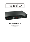
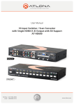
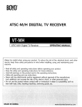
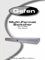
®
Multi-Format
Switcher
EXT-TV-MFS
User Manual
www.gefen.com
f
ASKING FOR ASSISTANCE
Technical Support:
Telephone
Fax
(818) 772-9100
(800) 545-6900
(818) 772-9120
Technical Support Hours:
8:00 AM to 5:00 PM Monday thru Friday PST
Write To:
Gefen, LLC
c/o Customer Service
20600 Nordhoff St
Chatsworth, CA 91311
www.gefen.com
[email protected]
Notice
Gefen, LLC reserves the right to make changes in the hardware, packaging and
any accompanying documentation without prior written notice.
EXT-TV-MFS is a trademark of Gefen, LLC
© 2010 Gefen, LLC, All Rights Reserved
All trademarks are the property of their respective owners.
Rev A8
CONTENTS
1.
Introduction
2.
Operation Notes
3.
Features
4.
Panel Layout
5.
Panel Descriptions
6.
Connecting And Operating The EXT-TV-MFS
7.
Multi Format Switcher Remote Description
8.
EXT-TV-MFS Remote Installation
9.
IR Code Configuration
10. RS-232 Serial Control Interface
11. RS-232 Serial Communication Commands
12. Specifications
13. Warranty
INTRODUCTION
Congratulations on your purchase of the TV Multi Format Switcher. Your
complete satisfaction is very important to us.
Gefen
Gefen delivers innovative, progressive computer and electronics add-on solutions
that harness integration, extension, distribution and conversion technologies.
Gefen’s reliable, plug-and-play products supplement cross-platform computer
systems, professional audio/video environments and HDTV systems of all sizes
with hard-working solutions that are easy to implement and simple to operate.
The Rack-mountable TV Multi Format Switcher allows you to view a wide
variety of analog and digital SD and HD video sources with audio at resolutions
up to 1080p -- all on one HDMI-compliant display. Anything from computers,
set-top boxes, satellite boxes, security cameras, Blu-ray and DVD players to the
next generation of hi-def gaming consoles (including the Xbox 360 and PS3)
can share a single HDMI display. Superior A/V signal quality is insured by the
3D comb filter and 3D noise reduction circuitry. The audio delay feature and
de-interlacing feature for 480i sources improves Standard-Definition console
gaming.
The Multi Format Switcher supports 2 Component, 2 Composite, 2 S-Video, and
1 VGA input source -- each with L/R analog audio in up to 2 channels. 2 HDMI
sources are also supported with embedded digital audio at up to 7.1 channels.
(The number of audio channels present in the HDMI output signal will depend on
what kind of audio is input). Any A/V source can be selected for viewing at any
time using the included IR remote or the front-panel A/V source selector buttons.
How It Works
Audio/video sources connect to the TV Multi Format Switcher on its inputs. An
HDMI-compliant display is connected to the HDMI output. The 5V DC power
supply is connected to the TV Multi Format Switcher. The currently selected
video source will appear on the output display in vibrant color.
Note: Only A/V source switching (not scaling) is performed with this product.
Therefore, when selecting the VGA input source you may encounter slight
shifts of the output image. Please consult your graphics card and/or display
documentation for options that will allow adjusting of the image position. Any of
our versatile scalers can be easily added at the HDMI output of this unit, such as
our GefenTV 1080P HDMI Scaler (GTV-HDMI-1080PS, available separately).
HDMI 1.3 Features Supported:
•
225 MHz Video Ampl. Bandwidth (up to 12 bit YUV 444 @ 1080p, 24/60Hz)
•
Deep Color (xv Color) at 12-bit resolution
•
Dolbytm TrueHD & DTS Master Audio
•
Lip-Sync & De-interlacing
1
OPERATION NOTES
READ THESE NOTES BEFORE INSTALLING OR
OPERATING THE EXT-TV-MFS
•
All analog video inputs will be converted to digital and will be output through
the HDMI outputs.
•
All analog audio inputs will be converted to digital audio and will be output
through the HDMI outputs. All digital audio inputs will be output through the
HDMI outputs.
•
Compatible with all HDMI and DVI* displays
•
HDMI/HDCP compliant
*When used with a HDMI to DVI adapter
2
FEATURES
Features
•
The Multi-Format Switcher allows many A/V sources to be switched to one
HDTV display
•
A/V sources include (2) Composite, (2) S-video, (2) Component, (1) VGA
and (3) HDMI.
•
Selectable de-interlacing of 480i/576i sources to 480p/576p
•
Supports HDTV resolutions up to 1080p@60fps
•
All inputs are format converted and output through a single HDMI output
•
Audio delay feature allows a delay of 150ms on all analog audio inputs
•
3D noise reduction (DNR) and 3D comb filter for cleaner A/V signals
•
Switching is initiated by front panel buttons or by IR remote control (included)
•
Automated or remote switching is also possible by sending control signals to
the integrated RS-232 serial communications port with a computer or control
automation device such as Crestron (tm)
•
HDMI 1.3 compliant with Deep Color and 10-bit signal processing
(1080p@24Hz - 60Hz)
•
HDMI 1.3 digital audio support (Dolby TrueHD, DTS-HD Master Audio, Lip
Sync, De-Interlacing)
•
Rack-mountable (hardware kit included)
•
HDCP compliant
Package Includes
(1) Multi Format Switcher
(1) 6-foot HDMI Cable M-M
(1) IR Remote control
(1) 5V DC Power Supply
(1) User’s Manual
(1) Set of Rack Ears
3
PANEL LAYOUT
Back Panel
1
1
2
2
3
3
4
4
5
5
6
6
7
7
8
8
9
9
10
11
12
10
13
14
15
Front Panel
Note: A dashed line indicates inputs which are associated, such as a video source
and its audio counterpart. Both will be merged into the HDMI output stream.
4
PANEL DESCRIPTIONS
Front Panel
1
HDMI Input 1 - Attach 1st HDMI input source here.
2
Composite Video Input - Connect incoming Composite Video source here.
3
Analog Audio Input for Composite Video - Attach cable with two L+R RCA jacks to
input up to 2 channels of analog audio associated with the Composite Video input.
4
S-Video Input - Connect S-Video source here using a single S-Video cable.
5
Analog Audio Input for S-Video - Attach cable with two L+R RCA-style jacks here to
input up to 2 channels of analog audio associated with the S-Video source.
6
Component Video Input - Connect Component Video source here.
7
Analog Audio Input for Component - Attach cable with two L+R RCA-style jacks
here to input up to 2 channels of analog audio associated with the Component source.
8
IR signal window - Receives IR commands from the IR Remote control.
9
Power Indicator LED - ON (red) when the Switcher is correctly powered.
10
Source Input Indicators 1-10 (blue LEDs) with Selector Buttons - Blue LEDs
Indicate the active A/V source. Buttons choose currently active Video input source.
Back Panel
1
480i/576i De-Interlace Button - Converts video to a de-interlaced signal. Improves
standard definition sources such as gaming consoles and broadcast television.
2
Audio Delay - Adds a short delay to output audio. Useful for console gaming.
3
RS-232 Port - Attach a DB9 serial cable here to upgrade the firmware using an
internet-enabled computer. Please call Gefen when attempting this operation.
4
Composite Input - Attach a cable having 1 x RCA Composite Video connector here.
5
Analog Audio Input for Composite Video - Attach cable with two L+R RCA-style
jacks here to input up to 2 channels of audio associated with Composite Video source.
6
S-Video Input - Connect a single cable with an S-Video connector here.
7
Analog Audio Input for S-Video - Attach cable with two L+R RCA-style jacks here to
input up to 2 channels of analog audio associated with S-Video input source.
8
Component Video Input - Connects a Component Video input here using a cable
terminated with 3 x RCA jacks (RGB).
9
Analog Audio Input for Component Video - Two L+R RCA-style jacks allow input of
up to 2 channels of analog audio associated with the Component Video source.
10
VGA (PC) Input - Connect a std. VGA (HD15) terminated video cable from a PC here.
11
3.5mm Audio Input -- Connect a 3.5mm stereo mini-jack to input up to 2 channels of
analog audio associated with the VGA video input signal.
12, 13
HDMI Inputs 2 & 3 -- Attach 2nd and 3rd HDMI Input sources here.
14
HDMI Output -- Connect your HDMI-Compliant Display to this output on the Switcher.
15
Power Receptacle -- Connect the DC Power Supply here to activate the Switcher.
5
CONNECTING AND OPERATING THE EXT-TV-MFS
1.
Connect the HDMI output on the Multi Format Switcher (Back Panel #14) to
the display using the supplied 6-foot HDMI cable.
2.
Connect analog A/V input sources to the Multi Format Switcher using usersupplied cables as follows:
•
Connect Component sources using a 3 x RCA Component video cable.
(Front 6, Back 8)
•
Connect up to two S-Video input sources. (Front 4, Back 6)
•
Connect up to two Composite sources (Front 2, Back 4)
•
Connect analog audio sources for Component, Composite and S-Video
inputs using 2 x RCA cables (Front 3,5,7 and Back 5,7,9)
3.
Connect up to three HDMI sources to EXT-TV-MFS (Front 1, Back 12, 13).
4.
Plug in the 5V DC power supply (Back Panel, 15). The Switcher will turn on
and the power indicator LED on the front panel (Front, 9) will glow red.
5.
Power on the HDMI-compliant output display and all A/V source(s).
6.
Select A/V input sources by using the push buttons on the front panel of the
EXT-TV-MFS or the buttons on the included Remote control, as follows:
•
Front Panel: Press the button located immediately over the name of
the desired input source. A blue LED indicator will light up to indicate
successful selection of the source. (Front, 10)
•
IR Remote: Push the button that corresponds to the input source.
Please refer to page 7 (opposite page) for detailed operation
instructions.
7.
To use the Audio Delay function, press the Audio Delay button on the back
left side of the Switcher (Back, 2).
8.
To de-interlace 480i or 576i input video into progressive mode video output,
press the de-interlacing button on the rear of the Switcher. This function will
only take effect on resolutions of 480i or 576i. (Back, 1)
9.
Note: The available output resolutions range from 480i/p and 576i/p to
1080i/p@60 Hz and 1920x1200@60Hz for computer video sources. Because
the Multi-Format Switcher is not a scaler, the output resolution will exactly match
the resolution of the selected input source.
6
MT-M
T-R
F
X
S
E
MULTI FORMAT SWITCHER REMOTE DESCRIPTION
CV1
CV2
SV1
SV2
CO1 CO2
PC
HD1 HD2
HD3
•
Labeled buttons select A/V input sources. For instance, Composite Video
Input 1 is selected by pressing the button labeled “CV1”. The PC VGA input
is labeled “PC”, and the first HDMI Input is labeled “HD1”. Other buttons
follow the same convention.
•
As soon as one of the A/V input sources is selected, the corresponding
source selection indicator (Blue LED) will light up on the front panel of the
EXT-TV-MFS unit and the Switcher will output that source on the video
display.
•
Selectable inputs include two (2) each Composite, S-Video, and Component
sources; one (1) VGA source; and three (3) HDMI inputs for a total of ten
(10) A/V inputs.
7
EXT-TV-MFS REMOTE INSTALLATION
1.
Remove battery cover from the back of the EXT-RMT-MFS remote.
2.
Verify that DIP switches 1 & 2 are in the down (OFF) position. (See page 13)
3.
Insert the battery, hold the battery so that you can see the positive side
facing up. The side that is not marked must be facing down.
4.
Test the EXT-RMT-MFS remote by pressing ONLY one button at a time. The
indicator light on the remote will flash once each time you press a button.
WARNING:
Do not press multiple buttons simultaneously and do NOT press buttons rapidly.
These actions will cause the remote to reset and steps 1-4 will have to be
repeated.
MT-M
T-R
F
X
S
E
Note: The EXT-RMT-MFS ships with two batteries. Only one battery is required
for operation, the other battery is complimentary.
CV1
CV2
SV2
CO1 CO2
PC
HD1 HD2
HD3
8
SV1
IR CODE CONFIGURATION
How to Resolve IR Code Conflicts
In the event that IR commands originating from other remote controls conflict
with the supplied remote control, the EXT-RMT-MFS remote control has DIP
SWITCHES for setting the remote channel. The Multi Format Switcher must be
set to use the same remote channel. Please see page 10 for instruction son how
to set the IR channel on the Multi Format Switcher. By default, both the Multi
Format Switcher and the EXT-RMT-MFS remote control are set to Channel 1.
Remote Channel 1:
Default
Remote Channel 2:
1
2
Remote Channel 3:
1
2
1
2
Remote Channel 4:
1
2
EXTENDING THE IR RANGE
The optional IR extender (Gefen part # EXT-RMT-IREXT) allows you to
relocate your HDMI Switcher and still retain IR control.
9
RS-232 SERIAL CONTROL INTERFACE
What features are available via the RS-232 serial communications port?
The TV Multi Format Switcher can accept commands through the RS-232 serial
communications port located on the rear panel. The current RS-232 control
commands allow switching/routing of A/V inputs to outputs without the use of the
IR remote control.
How do I use these features?
These features were initially intended for utilization by custom installers in
automated setups. However, these features can be tested by using any computer
equipped with a 9-pin serial port and a terminal emulation program.
What pins are used to communicate with the TV Multi Function Switcher?
Only pins 2 (Receive), 3 (Transmit), and 5 (Ground) are used for communication.
A straight-through cable should be used with this Switcher.
54321
12345
9876
6789
Only Pins 2 (RX), 3 (TX), and 5 (Ground) are used on the RS-232 serial interface
What are the RS-232 communications port settings?
Bits per second .............................................................................................. 9600
Data bits ............................................................................................................... 8
Parity ............................................................................................................. None
Stop bits ................................................................................................................1
Flow Control .................................................................................................. None
10
RS-232 SERIAL COMMUNICATION COMMANDS
Commands
These commands are sent in ASCII format to the Switcher:
Command Code
Response
S POWER 0
> POWER OFF
S POWER 1
> POWER ON
POWER ON
S SOURCE 0
> SOURCE HDMI1
HDMI1 INPUT
S SOURCE 1
> SOURCE HDMI2
S SOURCE 2
> SOURCE HDMI3
S SOURCE 3
> SOURCE PC
S SOURCE 4
> SOURCE COMP1
S SOURCE 5
> SOURCE COMP2
S SOURCE 6
> SOURCE SV1
S SOURCE 7
> SOURCE SV2
S SOURCE 8
> SOURCE CV1
Description
POWER OFF
HDMI2 INPUT
HDMI3 INPUT
PC INPUT
COMPONENT1 INPUT
COMPONENT2 INPUT
SV1 INPUT
SV2 INPUT
CV1 INPUT
S SOURCE 9
> SOURCE CV2
S AUDIODELAY 0
> AUDIODELAY OFF
CV2 INPUT
S AUDIODELAY 1
> AUDIODELAY ON
S SD_ITOP 0
> 480i/576i TO 480p/576p OFF
S SD_ITOP 1
>480i/576i TO 480p/576p ON
S RESET 1
> RESET ON
OFF : NO DELAY
ON : DELAY 150ms
OFF : NO 480i/576i TO 480p/576p
ON : 480i/576i TO 480p/576p
RESET ACTION
Command Code
Response
R POWER
> POWER ON~OFF
Description
R SOURCE
> SOURCE HDMI~CV
R AUDIODELAY
> AUDIODELAY OFF~ON
R SD_ITOP
>480i/576i TO 480p/576p OFF~ON
R FW_VER
> FIRMWARE VERSION : Vx.xx
11
SHOW POWER STATUS
SHOW SOURCE STATUS
SHOW AUDIO DELAY STATUS
SHOW 480i/576i TO 480p/576p STATUS
SHOW FIRMWARE VERSION
SPECIFICATIONS
Digital Maximum Pixel Clock ......................................................................225 MHz
Analog Video Amplifier Bandwidth ............................................................ 350 MHz
Maximum Resolution: ..................................................... 1080p/1920 x 1200@60Hz
Input DDC Signal ......................................................................... 5 Volts p-p (TTL)
Input Video Signal .............................................................................. 1.2 Volts p-p
HDMI Input Connector: ....................................................(3) Type A 19 Pin female
HDMI Output Connector:.................................................. (1) Type A 19 Pin female
Component Input Connector: ......................................................(2) YPbPr (3 RCA)
Composite Input Connector: .......................................................(2) CVBS (1 RCA)
VGA Input Connector: ..........................................................(1) HD-15 female VGA
S-video Input connector: ...........................................................(1) 4 pin mini-DIN
RS-232 Remote Control Port.......................................................... DB9 9-pin Serial
Analog Audio Inputs:....................(2) pair L+R RCA, (1) 3.5mm stereo mini-jack
Rack Size: .........................................................................1U (rack ears included)
Power Supply:............................................................................. 5V DC / 2.6 Amps
Power Consumption ....................................................................... 13 Watts (max)
Dimensions .............................................................. 17.3’’ W x 1.8’’ H x 6.3’’ D
Shipping Weight ............................................................................................ 8 lbs.
12
13
Rev A8
20600 Nordhoff St., Chatsworth CA 91311
1-800-545-6900
818-772-9100
www.gefen.com
fax: 818-772-9120
[email protected]