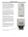
1
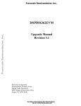
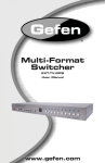
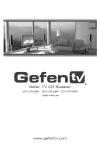
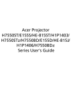
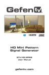
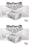
Wireless for
60 GHz Extender
GTV-WIRELESSHD
User Manual
www.gefentv.com
ASKING FOR ASSISTANCE
Technical Support:
Telephone
Fax
(818) 772-9100
(800) 545-6900
(818) 772-9120
Technical Support Hours:
8:00 AM to 5:00 PM Monday through Friday, Pacific Standard Time.
Write To:
Gefen, LLC
c/o Customer Service
20600 Nordhoff St
Chatsworth, CA 91311
www.gefentv.com
[email protected]
Notice
Gefen, LLC reserves the right to make changes in the hardware, packaging and
any accompanying documentation without prior written notice.
Wireless for HDMI 60 GHz is a trademark of Gefen, Inc.
© 2010 Gefen, LLC, All Rights Reserved
All trademarks are the property of their respective owners
Rev A9
CONTENTS
1
Introduction to the Wireless for HDMI 60 GHz
2
Operation Notes
3
Features
4
Sender / Receiver Panel Layout
5
Sender / Receiver Panel Descriptions
6
Sender / Receiver Panel Layout, Continued (Side Panel, LEDs)
7
Connecting the Wireless for HDMI 60 GHz Sender and Receiver
8
Infrared Remote Control
9
Specifications
10 Warranty
INTRODUCTION
Congratulations on your purchase of the Wireless for HDMI 60 GHz. Your
complete satisfaction is very important to us.
GefenTV
GefenTV is a unique product line catering to the growing needs for innovative
home theater solutions. We specialize in total integration for your home theater,
while also focusing on going above and beyond customer expectations to insure
that you get the most from your hardware. We invite you to explore our distinct
product line and hope that you find what you need. Do you find that a particular
product is not carried on our website? Please call us so we can better assist you
with your particular needs.
The GefenTV Wireless for HDMI
The GefenTV Wireless for HDMI 60 GHz Extender delivers a plug-and-play
wireless solution for HDMI sources placed up to 30 feet (9 meters) away. Hi-def
resolutions of up to 1080p/60 fps are supported with 8-channel embedded digital
audio.
The GefenTV Wireless for HDMI 60 GHz Extender is a wireless solution for
extending any HDMI A/V sources to a remote HDMI-compliant display such as
satellite boxes, DVD players, and Blu-Ray players. The Wireless for HDMI 60
GHz operates best in open indoor spaces with minimum obstructions between
the Sender and Receiver units. Range will be significantly reduced otherwise.
How It Works
The GefenTV Wireless for HDMI 60 GHz Extender uses one Sender and one
Receiver unit. A short cable connects the HDMI input of the Sender unit to the
HDMI output of an HDMI source. At the display side, a short cable connects the
HDMI output of the Receiver unit to the HDMI input of the HDTV display. Power
is applied to the Sender and Receiver. There is a slight pause while the Sender
and Receiver locate each other and begin communicating. The HDMI signal
from the HDMI source then travels to the HDMI display over 60 GHz radio waves
and a vibrant and crisp High Definition picture emerges on the HDTV display.
Indicator lights on the front panels of both units assist in troubleshooting should
there be objects in the path of the radio waves or other problems to resolve.
Note on Multichannel Audio: Compressed audio as well as analog audio are
formats supported depending on the capability of the input device. Please refer to
the Specifications section for further details.
1
OPERATION NOTES
READ THESE NOTES BEFORE INSTALLING OR
OPERATING THE WIRELESS FOR HDMI 60 GHZ
This radio equipment may only be operated indoors. Operation outdoors is
in violation of 47 U.S.C.301 and could subject the operator to serious legal
penalties.
Federal Communication Commission
Interference Statement
1.
This device complies with Part 15 of the FCC Rules. Operation is
subject to the following two conditions: (1) this device may not cause
harmful interference, and (2) this device must accept any interference
received, including interference that may cause undesired operation.
2.
NOTE: This equipment has been tested and found to comply with
the limits for a Class B digital device, pursuant to Part 15 of the FCC
Rules. These limits are designed to provide reasonable protection
against harmful interference in a residential installation. This equipment
generates, uses, and can radiate radio frequency energy and, if not
installed and used in accordance with the instructions, may cause
harmful interference to radio communications.
3.
In order to comply with FCC RF Exposure requirements, a separation
distance of at least 20 cm must be maintained between the antenna and
all persons. However, there is no guarantee that interferenc occur in a
particular installation. If this equipment does cause harmful interference
to radio or television reception, which can be determined by turning
the equipment off and on, the user is encouraged to try to correct the
interference by one or more of the following measures:
4.
Reorient or relocate the device(s) causing the interference.
5.
Increase the separation between the devices.
6.
Connect equipment into an outlet on a circuit different from that to which
the device experiencing interference is connected.
7.
Consult the dealer or an experienced radio/TV technician for help.
2
FEATURES
Features
•
30-ft maximum extension distance if set up properly in a wide open indoor
environment
•
Fully HDMI 1.3 compliant and HDCP (copy protection signal) compliant
•
CECS protocol pass-through supported
•
Uncompressed LPCM audio output support at up to 192 KHz (2 channels)
and up to 96 KHz (8 channels)
•
AC-3 (Dolbytm Digital) and DTStm at up to 8 channels / 192 KHz supported
•
36-element ceramic antenna array for good signal reception
•
Bank of LED indicators to show operational status
•
Dedicated system reset button on each unit
•
Low-power sleep mode for reduced power consumption (2.5W ea)
Package Includes
(1) Wireless for HDMI 60 GHz Sender unit
(1) Wireless for HDMI 60 GHz Receiver unit
(2) 12V DC Power Supply
(1) 6-Foot HDMI Cable (M-M)
(1) User’s Manual
(1) IR Remote Control
3
SENDER / RECEIVER PANEL LAYOUT
Front Panel
1
2
Back Panel
4
5
6
7
4
3
SENDER/RECEIVER PANEL DESCRIPTIONS
The Sender and Receiver units share the same identical panel layout:
1
IR window for remote control (Receiver Front Panel Only)
Receives the IR control signal from the IR remote.
2
LED Indicators (Front Panel x 3): Link, Weak Signal, Strong Signal
This bank of 3 LEDs provides operational status and aids troubleshooting during
the initial connection phase and sustained operation phase. LEDs will be in the
states of OFF, blinking and ON to indicate the connection link status and radio
signal strength. Please refer to pages 6 (bottom) and 7 (bottom) for a detailed
discussion of this functionality.
3
Power LED Indicator (Front Panel)
This LED indicator will become active once the included 12V DC power adapter
has been properly connected to the unit and a live power outlet.
4
12V DC Power Receptacle (Back Panel)
Connect the included 12V DC power supply to this receptacle and an available
household power outlet. Only use the power supply that is provided with this
product. Usage of a non-authorized power supply may damage the unit and
void the warranty.
5
Power Switch (Back Panel)
Turns the power on/off.
6
HDMI Input (Back Panel)
This input will accept a single HDMI source device. Use a DVI to HDMI cable/
adapter when using a DVI input device.
7
RS-232 Serial Port (Back Panel)
This port is reserved for firmware updates.
5
SENDER/RECEIVER PANEL LAYOUT, CONT’D
Right
g Side Panel
1
2
Front Right
g Panel
Close-Up
p of LED Indicators
Link
Weak Strong
6
Power
SENDER/RECEIVER PANEL LAYOUT, CONT’D
1
Reset Button (clears settings)
This button is used to reset the unit to default factory settings. To use the reset
button, insert a sharp object, push firmly then let go. A full reset operation takes
approximately 5 seconds.
2
CFG (Configuration Buttons)
These two push buttons are reserved for factory use only.
CONNECTING THE SENDER AND RECEIVER
1.
Connect the HDMI source device to the Wireless HD 60 GHz Sender input
using the supplied HDMI input cable. Use a DVI to HDMI cable/adapter
when using a DVI source device.
2.
Connect the HDMI-compliant display to the Receiver’s HDMI output port
using a user- supplied HDMI cable. Use a HDMI to DVI cable/adapter when
using a DVI-compliant display.
3.
Sender and Receiver should be oriented in a visually unobstructed, line-ofsight path without objects between them, at the same height as each other,
preferably in a wide open indoor area with tall ceilings.
4.
Connect the included 12V power supplies to the Wireless HD 60 GHz
Sender and Receiver units. Power on the display device (monitor or
projector).
5.
Switch on the Receiver and Sender units. Automatic pairing (linkup) will
begin. The units will search for each other, and four (4) LED indicators on the
front right hand panel of the units will indicate operational status as follows
(Please see diagram on the bottom of page 6, opposite):
LINK:
OFF (connection failed, try again), ON (connection good),
BLINKING (waiting for link completion)
WEAK:
OFF (no signal),
ON (wireless signal is weak)
STRONG: OFF (weak signal), ON (wireless signal is strong)
POWER: OFF (power off), ON (unit ON), BLINKING (unit sleeping)
*If 4 LEDs blink at once despite multiple power ON/OFF attempts, do not
continue operation. Please call Gefen Technical Support at 1-800-545-6900.
If a pairing operation does not commence and/or the WEAK LED stays
on, the units must be relocated for better signal reception. To retry pairing,
relocate them and reapply power.
7
REMOTE CONTROL
The included remote control has two
buttons on it, one labelled “HDMI” and one
labelled “SLEEP”. Only the SLEEP button
functions on the Wireless for HDMI 60
GHz. Its purpose is to put the Wireless for
HDMI 60 GHz system into standby mode
so that it can be kept ready for use at
any time without consuming a significant
amount of electrical power.
To use the SLEEP function, aim the
remote at either the Sender or Receiver
and press the “SLEEP” button on the
remote to place the units into a standby
mode. During this time the Power LEDs
on both units will flash to confirm that
SLEEP mode is active. To re-activate the
Wireless for HDMI 60 GHz system, press
the SLEEP button again.
The remote control runs off of a single
CR2032 battery (included). To change
the battery, push in the retaining clip
inward from the side rear of the remote
while simultaneously pulling the battery
containment sleeve out of the rear of the
remote. Note the positive orientation of
the battery facing upwards. Replace with
an identical type of battery in the same
orientation.
When operating the remote control for the
first time, please remove the protective
acetate plastic sheet inserted between
the circuit board and the battery. This
insert keeps the battery from prematurely
discharging in transit.
Battery Compartment
8
SPECIFICATIONS
AV Parameters:
Frequency band range ............................................................................................... 60 GHz
HDMI Versions Supported......................................................................... v1.3, 1.2a, 1.2, 1.1
Max. Distance Rating (Open air line of sight) .............................................................. 30 feet
Maximum Video Resolution: .................................................................. 1920x1080 @ 60 Hz
Maximum Audio Bandwidth: ...............................................8-channel, 24-bit / 96 kHz LPCM
Supported Video Formats:
HDTV: 640x480i/p @60Hz; 720x480p@60Hz; 720x576i/p@50Hz; 1280x720p at
50,60Hz; 1920x1080i@50,60Hz; 1920x1080p@24,50,60Hz.
Deep Colorr is supported by all of the above formats except 1920x1080p.
PC: Supported VESA computer display formats at 60 Hz: 640x480 (VGA),
800x600, 1024x768, and 1280x1024.
Connectors and Indicators for both Sender and Receiver (identical):
A/V Connector: (rear).........................................................One (1) Female 19-pin HDMI port
Power Connector: (rear).................................................................One (1) 12V DC input jack
Power Switch: (rear)...................................................................One (1) sliding rocker switch
Reset Button: (side).......................................... One (1) recessed push button on side panel
LED Indicators (4): .......................................Power/Sleep, Strong Signal, Weak Signal, Link
Physical and Electrical Characteristics:
Dimensions (ea): ..........................................7.35” W x 1.78” H x 3.35” D (units are identical)
Humidity:...........................Operating: 10%-90% relative, non-condensing; Storage: 5%-90%
Power Supply / Consumption: ..................................12V DC / 18W each (sleep mode 2.5W)
Transmitting Power (ea unit): ......................................................................................27 dBm
Receive Sensitivity: ....................................................................................................-65 dBm
Operating temperature: ............................0 to 40 degrees C (AC adapter is 0-40 degrees C)
Storage temperature: ...............................................................................-30 to 70 degrees C
Shipping Weight .............................................................................................................. 4 lbs
9
WARRANTY
Gefen warrants the equipment it manufactures to be free from defects in material
and workmanship.
If equipment fails because of such defects and Gefen is notified within two (2)
years from the date of shipment, Gefen will, at its option, repair or replace the
equipment, provided that the equipment has not been subjected to mechanical,
electrical, or other abuse or modifications. Equipment that fails under conditions
other than those covered will be repaired at the current price of parts and labor in
effect at the time of repair. Such repairs are warranted for ninety (90) days from
the day of reshipment to the Buyer.
This warranty is in lieu of all other warranties expressed or implied, including
without limitation, any implied warranty or merchantability or fitness for any
particular purpose, all of which are expressly disclaimed.
1.
Proof of sale may be required in order to claim warranty.
2.
Customers outside the US are responsible for shipping charges to and from
Gefen.
3.
Copper cables are limited to a 30 day warranty and cables must be in their
original condition.
The information in this manual has been carefully checked and is believed to
be accurate. However, Gefen assumes no responsibility for any inaccuracies
that may be contained in this manual. In no event will Gefen be liable for
direct, indirect, special, incidental, or consequential damages resulting from
any defect or omission in this manual, even if advised of the possibility of such
damages. The technical information contained herein regarding the features and
specifications is subject to change without notice.
For the latest warranty coverage information, please visit Gefen’s Warranty web
page at http://www.gefen.com/kvm/aboutus/warranty.jsp
PRODUCT REGISTRATION
Please register your product online by visiting Gefen’s web site at
http://www.gefen.com/kvm/Registry/Registration.jsp
10
Rev A9
20600 Nordhoff St., Chatsworth CA 91311
1-800-545-6900
818-772-9100
www.gefentv.com
Pb
fax: 818-772-9120
[email protected]