1
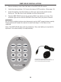
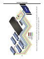
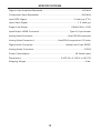
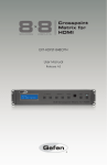
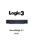
Multi Format Switcher
GTV-MFS
User Manual
www.gefentv.com
ASKING FOR ASSISTANCE
Technical Support:
Telephone
(818) 772-9100
(800) 545-6900
Fax
(818) 772-9120
Technical Support Hours:
8:00 AM to 5:00 PM Monday thru Friday.
Write To:
Gefen Inc.
c/o Customer Service
20600 Nordhoff St
Chatsworth, CA 91311
www.gefentv.com
[email protected]
Notice
Gefen Inc. reserves the right to make changes in the hardware, packaging and any
accompanying documentation without prior written notice.
Multi Format Switcher is a trademark of Gefen Inc.
HDMI™ is a trademark of HDMI.org
© 2008 Gefen Inc., All Rights Reserved
TABLE OF CONTENTS
1. Introduction / Operation Notes
2. Features
3. Panel Descriptions
4. Connecting and Operating the Multi Format Switcher
5. RMT-SR-IR Remote Description
6. Multi Format Switcher Configuration / Entering The Menu System /
Main Menu / Video
7. Multi Format Switcher Configuration / Video Continued
8. Multi Format Switcher Configuration / Output / Color
9. Multi Format Switcher Configuration / Color Continued / OSD
10. Multi Format Switcher Configuration / OSD Continued / Audio
11. Multi Format Switcher Configuration / Information
12. RMT-SR-IR Installation
13. IR Code Configuration
14. Wiring Diagram
15. Specifications
16. Warranty
INTRODUCTION
Congratulations on your purchase of the Multi Format Switcher. Your complete
satisfaction is very important to us.
Gefen TV
Gefen TV is a unique product line catering to the growing needs for innovative
home theater solutions. We specialize in total integration for your home theater,
while also focusing on going above and beyond customer expectations to ensure you get the most from your hardware. We invite you to explore our distinct
product line and hope you find your solutions.. Don’t see what you are looking for
here? Please call us so we can better assist you with your particular needs.
The Gefen TV Splitter
The Gefen TV Multi Format Switcher allows you to upscale and switch your
standard definition or high definition component and HDMI sources to resolutions
up to 1080p. Anything from set-top boxes, DVD players to the next generation of
gaming consoles including the Xbox 360 and PS3 can be plugged into the Multi
Format Switcher.
How It Works
You simply connect all your components and your display. Easy to use on-screen
menus are accessible through the IR remote control. The IR remote control allows for effortless setup and image adjustment to accommodate different viewing
modes and screen sizes to perfect your final picture. .
OPERATION Notes
READ THESE NOTES BEFORE INSTALLING OR
OPERATING THE Multi Format Switcher
•
When initially powering on HDMI sources, it is important to have the Multi
Format Switcher for HDMI’s output selected to that source to ensure that the
EDID is relayed properly.
•
Compatible with all HDMI and DVI* displays
•
The Multi Format Switcher has a 15-foot limit on how far it can transmit the
DDC (Display Data Channel) information out of the HDMI output jack to the
display. Connections to displays at distances longer than 15 feet should use a
true DDC re-clocking solution such as our CAT-5 based HDMI signal extender
device (Gefen part number EXT-HDMI-CAT5-MS).
•
HDMI/HDCP compliant
*When used with a HDMI to DVI adapter
1
FEATURES
Features
•
Both digital and analog inputs are format converted and pixel re-scaled
through the Home Theater Scaler Plus. It outputs a large range of formats
and resolutions that will easily match the native resolution/ format of your
display to ensure highest picture quality.
•
DVI/HDCP/HDMI compliant input: Operates up to 165MHz (Up to UXGA
@60Hz)
•
Supports digital HD output up to 1080p.
•
Integrated 8-bit triple-ADC/PLL.
•
Integrated DVI/HDCP/HDMI compliant receiver.
•
Dual high quality scaling engines.
•
Dual 3-D motion video adaptive de-interlacers with smooth low-angle edge.
•
Automatic 3:2 pull-down & 2:2 pull-down detection and recovery.
•
High performance frame rate conversion engine.
•
The Proprietary Advanced Color Engine technology gives: Brilliant and fresh
color, Intensified contrast and details, Vivid skin tone, Sharp edge, Accurate
and independent color control
•
Option to select Audio input from HDMI or TOSlink/SPDIF audio source.
•
3D noise reduction on analog inputs only.
•
Operates through on-screen OSD menu control and remote control.
•
Aspect Ratio Control
•
Digital Audio Delay to match audio/video timing
•
Less then one frame delay allowing for gaming
Package Includes
(1) Multi Format Switcher
(1) 6 ft HDMI cable (M-M)
(1) 5V DC Power Supply
(1) RMT-SR-IR Remote control
(1) User’s Manual
2
PANEL DESCRIPTIONS
Input LED
Indicator
Power
LED Indicator
IR Eye
Composite Input
Analog Audio
Input
Power
S-Video Input
HDMI
Output
SPDIF
Out
Optical
Out
Component Audio
Input
Component Input
HDMI
Input 2
SPDIF
In 2
HDMI
Input 1
SPDIF
In 1
Optical
In 2
Optical
In 1
3
5V DC Power
Input
CONNECTING AND OPERATING THE MULTI FORMAT SWITCHER
How to Connect the Multi Format Switcher
1. Connect the HDMI output on the Multi Format Switcher to the display using
the supplied HDMI cable.
2. Connect either the digital SPDIF or digital Optical audio output to the display or
an external audio processor using user supplied digital audio cables.
3. Connect the sources to the Multi Format Switcher using user supplied
cables.
•
Connect up to two HDMI sources with optional digital SPDIF/Optical
audio using HDMI cables and digital audio cables.
•
Connect one Component source with analog audio using a 3 RCA
Component video cable and a 2 RCA analog audio cable.
•
Connect one S-Video source with analog audio using a S-Video cable
and one Composite source with analog audio using a 1 RCA Composite
video cable
•
Connect one analog audio source for the Composite and S-Video inputs
using a 2 RCA analog audio cable
NOTE: The Composite and S-Video share a single audio input.
4. Plug the 5V DC power supply into the Multi Format Switcher.
5. Press the POWER button on the RMT-SR-IR remote to begin operation of
the Multi Format Switcher.
6. Power on the display.
7. Power on the source(s).
NOTE: When initially powering on HDMI sources, it is important to have the
Multi Format Switcher’s output selected to that source to ensure that the EDID is
relayed properly.
OPERATING THE MULTI FORMAT SWITCHER
The Multi Format Switcher has a built in GUI for navigating the various functions.
The GUI is navigated by the included IR remote control. Please see the RMT-SRIR Remote Description on the next page for functional information.
4
RMT-SR-IR REMOTE DESCRIPTION
1
GTV-SR-IR
2
3
4
5
6
8
7
1. Output - Cycles through the available output resolutions. Please see the section
Multi Format Switcher CONFIGURATION / Output on page 8 for the output
resolution table.
2. Input - Cycles though all of input sources. The selectable inputs are
Composite, S-Video, Component, HDMI 1, and HDMI 2.
3. Power - Turns the unit on and off (standby).
4. Exit - Exits the current menu option and menu system.
5. Menu - Displays the menu system for adjustment of options.
6. Navigation Keys - These include up, down, left, and right buttons for
navigating the menu system. The OK button will select specific menu options
for adjustment and will also confirm/cycle-through selections.
7. Reset - Resets the input and output resolutions to factory default.
8. Auto Adjust - Sets the display for optimal resolution and aspect ratio based
on the display’s EDID information and the currently selected sources output
resolution.
5
MULTI FORMAT SWITCHER CONFIGURATION
Entering the Menu System
Pressing the Menu button on the included RMT-SR-IR remote control will display the
GUI (graphical user interface) for adjustment options.
The GUI is overlaid onto the outgoing video to the display. Therefore, the selected
source must be outputting a compatible resolution for viewing on the display. If video
is not visible on the display, the GUI will also fail to be displayed. To correct this,
please follow the steps below.
1. Verify that the source is on and outputting a video signal.
2. Verify that the RMT-SR-IR remote channel is in the default position (page 13).
3. Verify that the Multi Format Switcher is selected to the chosen source.
4. Press the Output button on the RMT-SR-IR remote control to cycle through
output resolutions until video is displayed.
Navigation
Use the directional buttons to navigate the menu system. Press the OK button to
enter a sub category and to select a menu item for adjustment. Press the EXIT
button to return to the previous menu. Use the LEFT and RIGHT buttons to adjust
selected options. Pressing the EXIT button while in the main menu will exit out of the
menu system.
MAIN MENU
The following are the main menu options. Use the UP and DOWN buttons to choose
your desired subcategory and press OK to enter it.
VIDEO
COLOR
OUTPUT
OSD
AUDIO
INFORMATION
VIDEO
Picture Mode
Preset and user configurable settings for different viewing scenarios. Preset settings
will not allow user adjustment. Only the USER option will allow customized video
settings. The USER settings are saved.
Options:
•
•
•
•
Standard - useful for general content
Movie - useful for dimly lit environments
Vivid - useful for accentuating colors for a more vibrant image
User - user configurable settings
NOTE: User settings are saved. However, user settings for the digital inputs (HDMI
1 and 2) are linked and user settings for the analog inputs (Composite, S-Video, and
Component) are linked. i.e. adjustments to video user settings made on HDMI 1 will
be reflected in HDMI 2.
6
MULTI FORMAT SWITCHER CONFIGURATION
VIDEO CONTINUED
Contrast
Adjusts the contrast in increments of 1 on a scale of 1 to 100 (default 50).
Brightness
Adjusts the brightness in increments of 1 on a scale of to 100 (default 50).
Hue
Adjusts the hue in increments of 1 on a scale of 1 to 100 (default 50).
Saturation
Adjusts the saturation in increments of 1 on a scale of 1 to 100 (default 50).
Sharpness
Adjusts the sharpness in increments of 1 on a scale of 1 to 100 (default 50).
Scale
Adjusts the aspect ratio of the video.
Options:
4:3 Source
16:9 Source
Full - Stretches the image to fill the screen
Overscan - Stretches the image to fullscreen and just beyond the border of the display
Underscan - Stretches the image to fullscreen and just within the border of the screen
Letterbox Underscan - Stretches the image to 16:9 aspect ratio with underscan
Pan Scan Underscan - Stretches the image to 4:3 aspect ratio with underscan
Letterbox Full - Stretches the image to 16:9 aspect ratio without underscan
Pan Scan Full - Stretches the image to 4:3 aspect ratio without underscan
N.R. (Noise Reduction) - Only for Composite and S-Video Inputs
Reduces video noise inherent in analog video signals.
Options:
•
•
•
•
Off - default
Low
Middle
High
H-Pos (Horizontal Position)
Adjusts the image’s horizontal position on the screen.
Option:
• Adjusts in increments of 1 on a scale of 1 to 100 (default is 50)
7
MULTI FORMAT SWITCHER CONFIGURATION
V-Pos (Vertical Position)
Adjusts the image’s vertical position on the screen.
Options:
• Adjusts in increments of 1 on a scale of 1 to 100 (default is 50)
Y/C Separation - Only for Composite Input
Selects the method in which the brightness and color are separated from the
composite video signal.
Options:
• Auto - automatically selects the optimal method (default)
• 2D - Separation based on single frame analysis
• 3D - Motion adaptive color separation based on multiple frame analysis
Coring - Only for Composite Input
Adjusts the threshold level for pixel noise evaluation. This relates to how much of the
image is processed in regards to noise reduction.
Options:
• Adjusts in increments of ~6.5 on a scale of 1 to 100. (default is 20)
Output
This menu sets the output resolution for all video sources. The OUTPUT button on
the RMT-SR-IR remote control cycles through these resolutions when pressed.
VGA
SVGA
XGA
SXGA
UXGA
480i
480p
720p 60
1080i 60
1080p 60
576i
576p
720p 50
1080i 50
1080p 50
WXGA
WSXGA
WUXGA
Native
Native
This option will select the native resolution of the connected display based on the
EDID from the display.
NOTE: If a resolution that is not supported by the display is selected, the menu GUI
will not longer be visible. To correct this, press the OUTPUT button on the RMT-SRIR remote control until a supported resolution is displayed.
8
MULTI FORMAT SWITCHER CONFIGURATION
COLOR
Color Tone
Sets the color for the appearance of white. Only the USER option will allow
customized settings. The USER settings are saved.
Options:
•
•
•
•
Normal - Normal white color appearance (default)
Warm - Slight red shift to white appearance
Cool - Slight blue shift to white appearance
User - User adjustments to Red, Green, and Blue
Red
Adjusts the red color in regards to the appearance of white for the USER setting.
Option:
Adjusts in increments of 1 from 1 to 100 (default is 50)
Green
Adjusts the green color in regards to the appearance of white for the USER setting.
Option:
Adjusts in increments of 1 from 1 to 100 (default is 50)
Blue
Adjusts the blue color in regards to the appearance of white for the USER setting.
Option:
Adjusts in increments of 1 from 1 to 100 (default is 50)
OSD (ON SCREEN DISPLAY)
H-Pos (Horizontal Position)
Adjusts the OSD’s horizontal position on the screen.
Options:
• Adjusts in increments of 1 on a scale of 1 to 100 (default is 50)
V-Pos (Vertical Position)
Adjusts the OSD’s vertical position on the screen.
Options:
• Adjusts in increments of 1 on a scale of 1 to 100 (default is 50)
Time Out
Adjusts the amount of idle time before the OSD is automatically exited.
Options:
• Adjusts in increments of 1 on a scale of 1 to 100 (default is 10)
Background
Sets the transparency level of the OSD background.
Options:
• Adjusts in increments of ~12.5 on a scale of 1 to 100 (default is 50)
9
MULTI FORMAT SWITCHER CONFIGURATION
OSD (ON SCREEN DISPLAY) CONTINUED
Remote Channel
Sets the remote channel for use with the RMT-SR-IR remote control. If the selected
channel in this menu and does not match the channel set in the RMT-SR-IR remote,
the unit will cease to respond to IR commands from the remote.
Options:
• Selectable remote channel from 1 to 4 (default is 1)
AUDIO
Source
Sets the audio source for current input.
Options for Composite:
• L/R1 - Analog audio input (default)
Options for S-Video:
• L/R1 - Analog audio input (default)
Options for Component:
• L/R2 - Component analog audio input (default)
Options for HDMI 1:
• HDMI1 - HDMI 1 internal audio (default)
• Optical1 - Optical input 1
• Coaxial1 - SPDIF input 1
Options for HDMI 2:
• HDMI2 - HDMI 2 internal audio (default)
• Optical2 - Optical input 2
• Coaxial2 - SPDIF input 2
Delay
Sets the audio delay for lip syncing correction.
Options:
• Off - No delay (default)
• 40ms - 40 millisecond audio offset
• 110ms - 110 millisecond audio offset
• 150ms - 150 millisecond audio offset
Sound
Select general audio output function
Options:
• On - Use selected audio source (default)
• Mute - No sound output
10
MULTI FORMAT SWITCHER CONFIGURATION
INFORMATION
This menu will allow the user to view general information. There are no configurable
options in this menu.
• Source - Displays current source
• Input - Displays current input source resolution
• Output - Displays current output resolution
• Version - Displays current firmware revision
11
RMT-SR-IR INSTALLATION
1. Remove battery cover from the back of the RMT-SR-IR remote.
2. Verify that dip switches 1 & 2 are in the down (OFF) position. (See page 13)
3. Insert the battery, hold the battery so that you can see the positive side
facing up. The side that is not marked must be facing down.
4. Test the RMT-SR-IR remote by pressing ONLY one button at a time. The
indicator light on the remote will flash once each time you press a button.
WARNING:
Do not press multiple buttons simultaneously and do NOT press buttons rapidly.
These actions will cause the remote to reset and steps 1-4 will have to be
repeated.
Note: The RMT-SR-IR ships with two batteries. Only one battery is required for
operation, the other battery is complimentary.
GTV-SR-IR
The optional IR extender allows you to
relocate your HDMI Switcher and still retain IR
control. Gefen part# EXT-RMT-IREXT
12
IR CODE CONFIGURATION
How to Resolve IR Code Conflicts
In the event that IR commands from other remote controls conflict with the
supplied RMT-SR-IR remote control, changing the remote channel will alleviate
this issue. The RMT-SR-IR remote control has DIP SWITCHES for configuring
the remote channel. The Multi Format Switcher must match the remote channel
set in the RMT-SR-IR remote control. Please see page 10 for instruction on how
to configure the channel on the Multi Format Switcher. By default, both the Multi
Format Switcher and the RMT-SR-IR remote control are set to Channel 1.
Remote
Remote Channel 1:
Default
Remote Channel 2:
1
2
Remote Channel 3:
2
1
2
Remote Channel 4:
1
13
1
2
14
Maximum analog audio and video cable length is 50 ft
Maximum HDMI cable length is 15 ft at 1080P resolution without the use of an HDMI-SB or HDMI-CAT5-EXT
HDMI
Component
S-Video
Composite
Digital Audio
Analog Audio
WIRING DIAGRAM
SPECIFICATIONS
Digital Video Amplifier Bandwidth ............................................................ 165 MHz
Component Video Bandwidth .................................................................. 350 MHz
Input DDC Signal ......................................................................... 5 Volts p-p (TTL)
Input Video Signal .............................................................................. 1.2 Volts p-p
Single Link Range ................................................................... 1080p/1920 x 1200
Input/Output HDMI Connector .............................................. Type A 19 pin female
Analog Video Connector ....................................................... One 3 RCA Component
Analog Video Connector 1 .................................... One RCA Composite or 1 S-Video
Digital Audio Connector .................................................. Optical and Coax SPDIF
Analog Audio Connector .............................................................................. 2 RCA
Power Consumption ....................................................................... 20 Watts (max)
Dimensions .............................................................. 6.875”W x 2.125”H x 6.875”D
Shipping Weight ............................................................................................ 4 lbs.
15
WARRANTY
Gefen warrants the equipment it manufactures to be free from defects in material
and workmanship.
If equipment fails because of such defects and Gefen is notified within two (2)
year from the date of shipment, Gefen will, at its option, repair or replace the
equipment, provided that the equipment has not been subjected to mechanical,
electrical, or other abuse or modifications. The two year warranty is only valid on
new products purchased as of January 2007. All products purchased before this
date still retain their 1 year warranty.
Equipment that fails under conditions other than those covered will be repaired at
the current price of parts and labor in effect at the time of repair. Such repairs are
warranted for ninety (90) days from the day of reshipment to the Buyer.
This warranty is in lieu of all other warranties expressed or implied, including
without limitation, any implied warranty or merchantability or fitness for any
particular purpose, all of which are expressly disclaimed.
1. Proof of sale may be required in order to claim warranty.
2. Customers outside the US are responsible for shipping charges to and from
Gefen.
3. Copper cables are limited to a 30 day warranty and cables must be in their
original condition.
The information in this manual has been carefully checked and is believed to
be accurate. However, Gefen assumes no responsibility for any inaccuracies
that may be contained in this manual. In no event will Gefen , be liable for direct,
indirect, special, incidental, or consequential damages resulting from any defect
or omission in this manual, even if advised of the possibility of such damages.
The technical information contained herein regarding the 1:4 Gefen TV Splitter
features and specifications is subject to change without notice.
16
*ma-MFS*
Rev X1
20600 Nordhoff St., Chatsworth CA 91311
1-800-545-6900
818-772-9100
www.gefentv.com
fax: 818-772-9120
[email protected]