1
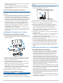
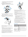
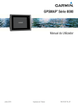
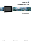
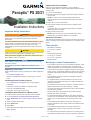
Updating the Device Software
Panoptix™ PS 30/31
Installation Instructions
Important Safety Information
WARNING
See the Important Safety and Product Information guide in the
product box for product warnings and other important
information.
You are responsible for the safe and prudent operation of your
vessel. Sonar is a tool that enhances your awareness of the
water beneath your boat. It does not relieve you of the
responsibility of observing the water around your boat as you
navigate.
CAUTION
Failure to install and maintain this equipment in accordance with
these instructions could result in damage or injury.
Always wear safety goggles, ear protection, and a dust mask
when drilling, cutting, or sanding.
NOTICE
When drilling or cutting, always check what is on the opposite
side of the surface.
This equipment should be installed by a qualified marine
installer.
Registering Your Device
Help us better support you by completing our online registration
today.
• Go to http://my.garmin.com.
• Keep the original sales receipt, or a photocopy, in a safe
place.
Contacting Garmin Product Support
®
• Go to www.garmin.com/support for in-country support
information.
• In the USA, call 913-397-8200 or 1-800-800-1020.
• In the UK, call 0808 238 0000.
• In Europe, call +44 (0) 870 850 1241.
Loading the New Software on a Memory Card
1 Insert a memory card into the card slot on the computer.
2 Go to www.garmin.com/support/software/marine.html.
3 Select Download next to "Garmin Marine Network with SD
4
5
6
7
card".
Read and agree to the terms.
Select Download.
Select Run.
Select the drive associated with the memory card, and select
Next > Finish.
March 2015
Before you can update the software, you must obtain a
software-update memory card or load the latest software onto a
memory card.
1 Turn on the chartplotter.
2 After the home screen appears, insert the memory card into
the card slot.
NOTE: In order for the software update instructions to
appear, the device must be fully booted before the card is
inserted.
3 Follow the on-screen instructions.
4 Wait several minutes while the software update process
completes.
The device returns to normal operation after the software
update process is complete.
5 Remove the memory card.
NOTE: If the memory card is removed before the device
restarts fully, the software update is not complete.
About the Transducer
The transducer transmits and receives sound waves through the
water, and relays sound-wave information to your Garmin sonar
device.
Tools Needed
•
•
•
•
•
•
•
#2 Phillips screwdriver
4 mm (5/32 in.) drill bit
Drill
Masking tape (optional)
13 mm (1/2 in.) Socket
13 mm (1/2 in.) Wrench
Marine sealant
Mounting Location Considerations
• The transducer should not be mounted behind strakes, struts,
fittings, water intake or discharge ports, or anything that
creates air bubbles or causes the water to become turbulent.
• The transducer can place a significant strain on less-rugged
trolling motors. Consider the weight and drag of the mounting
hardware and transducer before mounting it on the trolling
motor.
• The transducer must be in clean (non-turbulent) water for
optimal performance.
• For optimal results, mount the transducer as close to the
center line as possible. Mounting to one side can affect the
handling of the boat.
• The transducer should not be mounted in a location where it
might be jarred when launching, hauling, or storing.
• On single-drive boats, the transducer must not be mounted in
the path of the propeller.
• On twin-drive boats, the transducer should be mounted
between the drives, if possible.
• For the downward-facing transducer, the cables should be
routed out of the transducer to the starboard side of the boat,
with the logo on the transducer facing the port side of the
boat.
• The forward-facing transducer should be mounted in a
location that allows a view of the surface of the water in front
of the boat.
• The forward-facing transducer should be mounted in a
location that is out of the water at speeds over 40 km/h
(25 mph).
• For a forward-facing transducer mounted on a trolling motor,
the cables should be routed out of the transducer toward the
Printed in Taiwan
190-01885-02_0A
trolling motor (downward if mounted on the shaft, upward if
mounted below the motor).
• For a forward-facing transducer mounted on a transom
mount, the cables should be routed out of the transducer
toward the transom.
avoid any cracking in the gel-coat layer when the screws are
tightened.
1 Position the transducer mount À so the bottom of the
transducer sits below the water line.
Transducer Mounting Angle Considerations
NOTICE
The forward-view mount is not rated for speeds over 40 km/h
(25 mph).
• The internal attitude heading and reference system (AHRS)
sensor detects the mounting angle of the transducer in
relation to the water surface. When the Use AHRS setting is
turned off in the chartplotter installation menu, it is assumed
the transducer is mounted at a 45-degree angle and the
down-view transducer is mounted at a 0-degree angle.
• The higher the degree of the mounting angle and the more
vertical the transducer, the less a strong bottom echo
interferes with viewing targets in the water. To see more
suspended targets, you should mount the transducer at a
higher-degree, more vertical angle.
• To reduce rings that can appear with a strong bottom echo,
you should mount the transducer at a higher degree, more
vertical angle.
Installing the Transducer on a Transom
Assembling the Transom-Mount Hardware
1 Attach the transducer mount bracket À to the transducer Á
using four of the included 7 mm M4 mounting screws  and
M4 lock washers Ã.
2 Mark the location of the holes of the transducer mount.
3 Using a 4 mm (5/32 in.) bit, drill the pilot holes approximately
4
5
6
7
8
15 mm (19/32 in.) deep at the marked locations.
Apply marine sealant to four of the provided 8 mm M4
mounting screws, and attach the transducer assembly to the
transom using the M4 screws and M4 lock washers.
TIP: On boats with thinner hulls, you can place a wood
backing block inside the hull at the mounting spot to lessen
the pressure on the mounting screws.
If possible, route the cables to come out of the transducer on
the starboard side.
NOTE: If you must route the cables to come out the port side,
you must select the Flipped option in your chartplotter
installation menu for an accurate display.
For the downward-facing transducer, adjust the mount so the
transducer points straight down.
For the forward-facing transducer, adjust the mount so the
transducer points toward the front of the boat at an angle
based on the transducer mounting angle considerations.
For the forward-facing transducer, adjust the bolt tension to
allow the mount to close if the transducer collides with an
object.
Installing the Transducer on a Trolling Motor
Trolling Motor Mount Considerations
2 Attach the transducer mount bracket to the transom mount
bracket Ä using the included 16 mm M8 bolts Å, M8 flat
washers Æ, and M8 lock nuts Ç.
3 Route the Ethernet cable to the installation location of the
network switch or to the back of the MFD.
NOTE: The cable should not be routed close to electrical
wires or other sources of electrical interference.
TIP: Cutting the cables is not recommended, but a field
installation kit can be purchased from Garmin or a Garmin
dealer if cutting the cables is necessary.
4 Route the power cable to a 12 Vdc power source.
Installing the Transom-Mount Hardware
NOTICE
If you are mounting the bracket on fiberglass with screws, it is
recommended to use a countersink bit to drill a clearance
counterbore through only the top gel-coat layer. This will help to
2
• Placement of the transducer on a trolling motor depends on
the type of trolling motor you have installed on your boat.
Check with your trolling motor manufacturer for information
on the proper placement of your trolling motor mount.
• The transducer should be mounted on the shaft on most
cable-steered trolling motors, because the motor may not be
rugged enough to support the weight of the transducer and
mount. This mounting location blocks the view directly below
the trolling motor, but allows for a longer-range forward view
because there is less bottom interference. Mounting the
transducer on the shaft also offers more protection, and the
weight of the transducer and mounting hardware place less
strain on the trolling motor system
• The transducer should not be mounted on the motor of some
types of trolling motors, because the transducer can damage
the steering cables and bearings, and it can hit the boat hull
during deployment and retraction.
• The transducer can be mounted on the motor of some handsteered and wireless trolling motors, but you must make sure
you can safely deploy and retract the trolling motor with the
transducer attached.
• On trolling motors with steering cables, place the transducer
as close to the center line of rotation as possible to decrease
the resistance on the motor.
• Mount the transducer so it does not obstruct the motor from
its storage cradle or prevent the motor from being stowed
and deployed correctly.
Assembling the Trolling-Mount Hardware
1 Attach the transducer mount bracket À to the transducer Á
using the included 7 mm M4 mounting screws  and M4 lock
washers Ã.
2 Slide the hose clamps around the trolling motor Â.
3 With the motor placed as close to the center line of rotation
4
2 Attach the transducer mount bracket to the trolling mount
bracket Ä using the included 16 mm M8 bolts Å, M8 flat
washers Æ, and M8 lock nuts Ç.
5
Attaching the Transducer to a Trolling Motor Shaft
1 Insert the hose clamps À through the slots on the trolling
motor mount Á.
6
7
8
9
as possible, tighten the hose clamps.
Secure the transducer cable to the motor shaft or other
secure location.
NOTE: Ensure the trolling motor and transducer clear the
boat during deployment and retraction.
Route the Ethernet cable to the installation location of the
network switch or to the back of the MFD while taking these
precautions:
• The cable should not be routed close to electrical wires or
other sources of electrical interference.
• The cable must not be pinched when the trolling motor is
deployed and retracted.
• Cutting the cables is not recommended, but a field
installation kit can be purchased from Garmin or a Garmin
dealer if cutting the cables is necessary.
Add cable wraps to secure the cable, and provide a circular
service loop to allow the trolling motor to rotate.
Route the power cable to a 12 Vdc power source.
For a downward-facing transducer, adjust the mount so the
transducer points straight down.
For a forward-facing transducer, adjust the mount so the
transducer points toward the front of the boat at an angle
based on the transducer mounting angle considerations.
Specifications
Specification
2 Slide the hose clamps around the trolling motor shaft Â.
3 Tighten the hose clamps.
4 Secure the transducer cable to the shaft or other secure
location.
5 Route the Ethernet cable to the installation location of the
network switch or to the back of the chartplotter.
NOTE: The cable should not be routed close to electrical
wires or other sources of electrical interference.
6 Route the power cable to a 12 Vdc power source.
7 Adjust the mount so it points toward the front of the boat at
an angle based on the transducer angle considerations.
Measurement
Dimensions (W x H x L) 9.1 x 4.2 x 17 cm (3.6 x 1.7 x 6.7 in.)
Weight
800 g (1.8 lb.)
Max. power usage
10 W
Temperature range
• Operating: From 0 to 40°C (from 32 to
104°F)
• Storage: From -40 to 70°C (from -40 to
158°F).
Material
ASA plastic
Maximum depth*
91 m (300 ft.)
Frequency
417 kHz
* Dependent upon transducer placement, water salinity, bottom
type, and other water conditions.
Attaching the Transducer to a Trolling Motor
1 Insert the hose clamps À through the slots on the trolling
motor mount Á.
3
Garmin and the Garmin logo are trademarks of Garmin Ltd. or its subsidiaries, registered in the USA and other countries. Panoptix™ is a trademark of Garmin Ltd. or its subsidiaries. These trademarks may
not be used without the express permission of Garmin.
®
© 2015 Garmin Ltd. or its subsidiaries
www.garmin.com/support