1
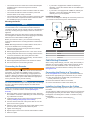
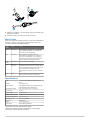
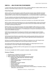
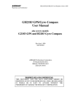
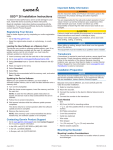
Important Safety Information GSD™ 24 Installation Instructions To obtain the best performance and to avoid damage to your boat, install the device according to these instructions. Read all installation instructions before proceeding with the installation. If you experience difficulty during the installation, contact Garmin Product Support. Registering Your Device Help us better support you by completing our online registration today. • Go to http://my.garmin.com. • Keep the original sales receipt, or a photocopy, in a safe place. Loading the New Software on a Memory Card The device may contain a software-update memory card. If so, follow the instructions provided with the card. If a software update memory card is not included, you must copy the software update to a memory card. 1 Insert a memory card into the card slot on the computer. 2 Go to www.garmin.com/support/software/marine.html. 3 Select Download next to “Garmin Marine Network with SD card.” 4 Read and agree to the terms. 5 Select Download. 6 Select Run. 7 Select the drive associated with the memory card, and select Next > Finish. Updating the Device Software Before you can update the software, you must obtain a software-update memory card or load the latest software onto a memory card. 1 Turn on the chartplotter. 2 After the home screen appears, insert the memory card into the card slot. NOTE: In order for the software update instructions to appear, the device must be fully booted before the card is inserted. 3 Follow the on-screen instructions. 4 Wait several minutes while the software update process completes. The device returns to normal operation after the software update process is complete. 5 Remove the memory card. NOTE: If the memory card is removed before the device restarts fully, the software update is not complete. Contacting Garmin Product Support • Go to www.garmin.com/support and click Contact Support for in-country support information. • In the USA, call (913) 397.8200 or (800) 800.1020. • In the UK, call 0808 2380000. • In Europe, call +44 (0) 870.8501241. WARNING See the Important Safety and Product Information guide in the product box for product warnings and other important information. You are responsible for the safe and prudent operation of your vessel. Sonar is a tool that enhances your awareness of the water beneath your boat. It does not relieve you of the responsibility of observing the water around your boat as you navigate. CAUTION Failure to install and maintain this equipment in accordance with these instructions could result in damage or injury. Always wear safety goggles, ear protection, and a dust mask when drilling, cutting, or sanding. NOTICE When drilling or cutting, always check what is on the opposite side of the surface. Transducers A transducer is required to send and receive a sonar signal from the sounder. Proper transducer selection and installation are critical to the operation of the device. Because mounting locations vary, see your local Garmin dealer or contact Garmin Product Support for more information. Go to www.garmin.com /transducers to select a transducer. If your compatible transducer does not have an 8-pin connector that is compatible with the device, see the Transducer Adapter Installation Instructions to install a transducer adapter. Installation Preparation NOTICE This device must be installed according to these instructions to get the best possible performance. If you experience difficulty with the installation, contact Garmin Product Support. Because every boat is different, you must carefully plan the GSD 24 sounder installation. 1 Select a mounting location. 2 Mount the sounder. 3 Connect the sounder to the Garmin Marine Network and to power. 4 Connect the sounder to the transducer. Tools Needed • Drill • #8 (5 mm) drill bit for mounting surface • 1 1/4 in. (32 mm) paddle drill bit or hole saw for mounting surface • #2 Phillips screwdriver • 3 mm flat screwdriver • Cable ties (optional) • Wire cutter • Wire stripper • Marine sealant (optional) Mounting the Sounder Mounting Location Considerations • The sounder must be mounted in a location where it cannot be submerged. September 2014 Printed in Taiwan 190-00789-02_0D • The sounder must be mounted in a location with adequate ventilation where it will not be exposed to extreme temperatures. • The sounder should be mounted so that the LEDs are visible. • The sounder should be mounted so that the power and network cables can be easily connected. • The sounder should be mounted so that the transducer cable can be connected. If required, transducer extension cables are available through your Garmin dealer. • If your boat is equipped with a GMS 10 network port expander, connect the network cable to an available port on the GMS 10. • If your boat is not equipped with a GMS 10 network port expander, connect the network cable directly to the network port on your chartplotter. Installation Diagram You can use this diagram to identify the connection points from your sounder to the network, power, and transducer. Mounting the Device NOTICE If you are mounting the bracket on fiberglass with screws, it is recommended to use a countersink bit to drill a clearance counterbore through only the top gel-coat layer. This will help to avoid any cracking in the gel-coat layer when the screws are tightened. Stainless-steel screws may bind when screwed into fiberglass and overtightened. Garmin recommends applying an anti-seize lubricant to the screws before installing them. Before you mount the device, you must select a mounting location and determine the mounting hardware needed for the surface. NOTE: Mounting hardware is included with the device, but it may not be suitable for the mounting surface. 1 Place the device in the mounting location and mark the location of the pilot holes. Drill the appropriate pilot hole for one corner of the device. 2 3 Loosely fasten the device to the mounting surface with one corner and examine the other three pilot-hole marks. Mark new pilot-hole locations if necessary, and remove the 4 device from the mounting surface. 5 Drill the appropriate pilot holes for the other three marks. 6 Secure the device to the mounting location. Connecting the Sounder WARNING When connecting the power cable, do not remove the in-line fuse holder. To prevent the possibility of injury or product damage caused by fire or overheating, the appropriate fuse must be in place as indicated in the product specifications. In addition, connecting the power cable without the appropriate fuse in place will void the product warranty. NOTICE Do not force a cable into its port. Forcing the cable can damage the pins. If the cable is properly aligned, the cable should connect easily. Before you connect the sounder to the network, power, and the transducer, you must mount the sounder (Mounting the Sounder). 1 Route the cables using the appropriate tie wraps, fasteners, and sealant to secure the cables along the route and through any bulkheads or the deck. 2 Install the locking rings on the marine network and power cables (Installing Locking Rings on the Cables). 3 Connect the bare-wire end of the power cable to a 12 Vdc power source and to ground. 4 Align the notch on the end of the power cable with the power port on the device, and press the cable into place. 5 Tighten the locking ring. 6 Repeat steps 4 and 5 for the network and transducer cables. 7 Select an option: 2 Item À Á  à Description Chartplotter GSD 24 Power Source Transducer Cable Routing Grommets When routing cables through your boat, it may be necessary to drill holes to route the cables. Cable routing grommets can be used to cover cable installation holes. You can purchase grommets from your Garmin dealer or directly from Garmin at www.garmin.com. Connecting the Device to a Transducer Go to www.garmin.com or contact your local Garmin dealer to determine the appropriate type of transducer for your needs. 1 Follow the instructions provided with your transducer to correctly install it on your boat. Route the transducer cable to the sounder. 2 3 Connect the transducer cable to the XDCR port. Installing Locking Rings on the Cables Before you install locking rings on the cables, you must route the cables. To help make the cable-routing process easier, the locking rings are packaged separately from the cables. Each locking ring is packaged in a small bag with a number on the label for easy identification. 1 Separate the two halves of the locking ring À. 2 Align the two halves Á of the locking ring over the cable and snap them together. 3 Insert the o-ring  into the end of the connector. Blink Codes After the sounder is installed, it turns on when the chartplotter is turned on. The two-color (green and red) status LED on the sounder indicates its operational status. LED Color State Status Green Slow blink The sounder is connected to a chartplotter and is operating properly. You should see sonar data on the chartplotter. Red Slow blink The sounder is turned on, but is not connected to a chartplotter, or is waiting to connect to a chartplotter. If the sounder is connected to the chartplotter and this code persists, check the wiring connections. Red/ Green Slow blink The sounder is in test mode. Red Rapid blink sequence System error. The chartplotter displays a message indicating the type of failure. When the error condition is fixed, the sounder must be completely disconnected from and reconnected to its power source to clear the error. Red Solid The sounder has a hardware failure. Contact Garmin Product Support for assistance. Specifications Size L x W x H: 204 x 283 x 81 mm (8 x 11.2 x 3.2 in.) Weight 2.39 kg (5.27 lb.) Case material Fully gasketed, aluminum and steel housing, water resistant to IEC 60529 IPX7. Temperature range From 5 to 158°F (from -15 to 70°C) Power input 10–35 V Power usage 40 W maximum Fuse 7.5 A Compass safe distance 40 cm (15.75 in.) Sounder power 25-2,000 W (RMS)* Frequency 50/200 kHz Depth 1,512 m (5,000 ft.)** Data output Garmin Marine Network *Dependent on transducer rating and depth **Maximum depth dependent on transducer, water salinity, bottom type, and other water conditions. 3 Garmin® and the Garmin logo are trademarks of Garmin Ltd. or its subsidiaries, registered in the USA and other countries. GSD and GMS™ are trademarks of Garmin Ltd. or its subsidiaries. These trademarks may not be used without the express permission of Garmin. Airmar™ is a trademark of Airmar Technology Corporation. TA-2013/325 © 2011–2014 Garmin Ltd. or its subsidiaries www.garmin.com/support