1
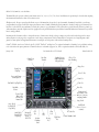
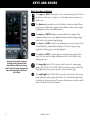
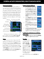
500W Series
Quick
Reference
© 2006-2014 Garmin Ltd. or its subsidiaries
This manual reflects the operation of Main System Software version 2.00, 3.00, 4.00, 5.00, 5.10, or later. Some differences in operation may be observed when comparing
the information in this manual to earlier or later software version.
All rights reserved. Except as expressly provided herein, no part of this manual may be reproduced, copied, transmitted, disseminated, downloaded or stored in any
storage medium, for any purpose without the express prior written consent of Garmin. Garmin hereby grants permission to download a single copy of this manual onto a
hard drive or other electronic storage medium to be viewed and to print one copy of this manual or of any revision hereto, provided that such electronic or printed copy
of this manual must contain the complete text of this copyright notice and provided further that any unauthorized commercial distribution of this manual or any revision
hereto is strictly prohibited.
Information in this document is subject to change without notice. Garmin reserves the right to change or improve its products and to make changes in the content
without obligation to notify any person or organization of such changes or improvements. Visit the Garmin Web site (www.garmin.com or https://fly.garmin.com/flygarmin) for current updates and supplemental information concerning the use and operation of this and other Garmin products.
Garmin®, GPSMAP®, AutoLocate®, TracBack®, Apollo, SafeTaxi®, FliteChart®, and MapSource® are registered trademarks of Garmin Ltd. or its subsidiaries and may
not be used without the express permission of Garmin. NavData® is a trademark of Jeppesen, Inc.; XM® is a registered trademark of XM Satellite Radio, Inc.
January 2014
Part Number 190-00357-01 Rev H
Graphic Moving
Map Display and
Navigation Info
Nav Freq
Window
Comm Freq
Window
Printed in the USA
Photocell for
Auto-Dimming
Range Keys
Comm Freq
Flip/Flop
Direct-To Key
Power and Comm
Volume/Squelch
Menu Key
Nav Radio Freq Flip/Flop
Clear Key
Enter Key
Nav Radio
Volume
Waypoint and
arrival alerts, turn
advisories, function,
and page number
Terrain, Flight
Phase, and
GPS Integrity
Annunciator
Large Knob
Large Knob
Comm/VLOC
Freq (MHz)
Small Knob
Comm/VLOC
Freq (kHz)
Small Knob
(Cursor - Press to
activate)
Navigation
Source: GPS,
VLOC, or
GPS-PTK
CDI
Key
Aviation
Database
Card
OBS
Key
Procedure Key
Cam
Lock
Message
Key
Flight Plan
Key
Terrain Database Card
WARNINGS, CAUTIONS, and NOTES
WARNING: The altitude calculated by the 500W-series
is geometric height above mean sea level and could vary
significantly from altitude displayed by pressure altimeters in
aircraft.
WARNING: The Jeppesen database incorporated in the
500W-series must be updated regularly in order to ensure
that its information is current. Updates are released every
28 days. A database information packet is included in your
500W-series package. Pilots using an out-of-date database
do so entirely at their own risk!
WARNING: VNAV is to be used for advisory purposes only.
VNAV messages or vertical speed required should not be
used to maintain terrain or ATC clearances. Terrain and ATC
clearances are the sole responsibility of the pilot.
WARNING: Do not use data link weather information for
maneuvering in, near, or around areas of hazardous weather.
Information contained within data link weather products may
not accurately depict current weather conditions.
WARNING: Do not use the indicated data link weather
product age to determine the age of the weather information
shown by the data link weather product. Due to time delays
inherent in gathering and processing weather data for data
link transmission, the weather information shown by the
data link weather product may be significantly older than the
indicated weather product age.
CAUTION: The Global Positioning System is operated by the
United States government, which is solely responsible for its
accuracy and maintenance. The system is subject to changes
which could affect the accuracy and performance of all GPS
equipment. Although the Garmin 500W-series are precision
electronic NAVigation AIDs (NAVAID), any NAVAID can be
misused or misinterpreted and therefore become unsafe.
CAUTION: Use the 500W-series at your own risk. To reduce the
risk of unsafe operation, carefully review and understand all
aspects of this Owner’s Manual and the Flight Manual Supplement, and thoroughly practice basic operation prior to actual
use. When in actual use, carefully compare indications from the
500W-series to all available navigation sources, including the
information from other NAVAIDS, visual sightings, charts, etc.
For safety, always resolve any discrepancies before continuing
navigation.
receiver may create electromagnetic interference (EMI) which
may affect the ability of the GPS receiver to receive and
decode the satellite signals. In such event, the interference
may be reduced or eliminated by switching off the source of
interference or moving the GPS receiver away from it.
CAUTION: The electronic chart is an aid to navigation and
is designed to facilitate the use of authorized government
charts, not replace them. Land and water data is provided
only as a general reference to your surroundings. The positional accuracy of the land and water data is not of a precision suitable for use in navigation and it should not be used
for navigation. Only official government charts and notices
contain all information needed for safe navigation – and, as
always, the user is responsible for their prudent use.
CAUTION: The Terrain feature (in units not equipped with
TAWS) is for supplemental awareness only. The pilot/crew
is responsible for all terrain and obstacle avoidance using
information not provided by the 500W-series Terrain feature.
CAUTION: The Garmin 500W-series does not contain any
user-serviceable parts. Repairs should only be made by an
authorized Garmin service center. Unauthorized repairs or
modifications could void your warranty and authority to
operate this device under FCC Part 15 regulations.
NOTE: The GNS 500W-series units use a different database
than in the legacy units. The databases are incompatible between units. The GNS 500W-series units must use a WAAS
enabled database.
NOTE: This product, its packaging, and its components
contain chemicals known to the State of California to cause
cancer, birth defects, or reproductive harm. This notice is being provided in accordance with California’s Proposition 65. If
you have any questions or would like additional information,
please refer to our website at www.garmin.com/prop65.
NOTE: It is the pilot’s responsibility for initial missed approach guidance in accordance with published procedure. The
unit may not provide correct guidance until established on a
defined leg.
NOTE: GPS level of service annunciations (LPV, ENR, etc.)
are not applicable to the external CDI (or HSI) when VLOC is
active.
CAUTION: GPS receivers operate by receiving and decoding very low power radio signals broadcast by satellites. It
is possible that in some situations other radio equipment
or electronic equipment used in close proximity to a GPS
190-00357-01 Rev H
1
MODEL DESCRIPTIONS
Model Descriptions
This guide covers the operation of the GNS 530W, GNS
530AW, and the GPS 500W. In general, all models will be
referred to as the 500W-series, except where there are physical or operational differences. The 500W-series units are 6.25”
wide and 4.60” high. The display is a 320 by 234 pixel color
LCD. The units include two removable data cards, one with
a Jeppesen aviation database (inserted in the left-most card
slot) and the second is a Terrain database (inserted in the
right-most card slot).
GPS 500W
The GPS 500W is a GPS-only unit with a WAAS GPS
engine and is TSO C146a certified for en route, terminal,
precision, and non-precision approaches. The GPS 500W
can simultaneously give aviators vital approach information and weather and traffic data in relation to their
position on a large, color moving map display. Thanks to
a high-contrast color display, the information can be easily
read from wide viewing angles even in direct sunlight.
Its color moving map features a built-in database that
shows cities, highways, railroads, rivers, lakes, coastlines,
and a complete Jeppesen aviation database. The Jeppesen
database (that can be updated with a front-loading data
card) contains all airports, VORs, NDBs, Intersections, FSS,
Approach, DPs/STARs and SUA information. The obstacle
and terrain databases provide an aid to navigation to help
you work with approved navigation charts.
nect to XM Satellite Radio’s XM WX Weather Service via the
GDL 69 datalink receiver plus XM Audio with the
GDL 69A.
GNS 530W and GNS 530AW
The GNS 530W and GNS 530AW include all of the
features of the GPS 500W, and also include an IFR certified
airborne VHF communications transceiver and IFR certified airborne VOR/Localizer and Glideslope receivers. This
multi-purpose unit is available with either a 10-watt (GNS
530W) or 16-watt (GNS 530AW) Com transceiver. References to the GNS 530W also include the GNS 530AW.
Helicopter Installations
In Helicopter installations, the ownship icon is set to
a helicopter. When present, HTAWS will be used instead
of TAWS. See the Garmin Optional Displays Pilot’s Guide
Addendum P/N 190-00356-30 Rev G, or later, for HTAWS
information.
Pilots will enjoy the GPS 500W as an Multi-Function
Display (MFD), especially when it is coupled with traffic, lightning detection, and weather interfaces like Ryan
TCAD, TIS from the Garmin GTX 330 Mode S transponder,
L3 SKYWATCH™, or STORMSCOPE® WX 500. With the
Fault Detection and Exclusion (FDE) prediction program
included with the Trainer CD, the GPS 500W may be used
for oceanic or remote operations. For the latest in graphical
and textual weather information, the GPS 500W can con2
190-00357-01 Rev H
KEYS AND KNOBS
Left-hand Keys and Knobs
k
The COM power/volume knob controls unit power and, in the
GNS 530W, communications radio volume. Press momentarily to
disable automatic squelch control. Turn clockwise to turn the unit
on.
j
In the GNS 530W, the VLOC volume knob controls audio volume
for the selected VOR/ Localizer frequency. Press momentarily to
enable/disable the ident tone.
y
In the GNS 530W, the large left knob (COM/VLOC) is used to
tune the megahertz (MHz) value of the standby frequency for the
communications transceiver (COM) or the VOR/Localizer receiver,
whichever is currently selected by the tuning cursor.
v
In the GNS 530W, the small left knob (PUSH C/V) is used to tune
the kilohertz (kHz) value of the standby frequency for the communications transceiver (COM) or the VLOC receiver, whichever
is currently selected by the tuning cursor. Press this knob momentarily to toggle the tuning cursor between the COM and VLOC
frequency fields.
W
In the GNS 530W, the COM flip-flop key is used to swap the
active and standby COM frequencies. Press and hold to select the
emergency channel (121.500 MHz).
V
In the GNS 530W, the VLOC flip-flop key is used to swap the
active and standby VLOC frequencies
(i.e., make the selected standby frequency active).
190-00357-01 Rev H
GPS 500W
GNS 530W
On the GNS 530W, the large and small left knobs
allow you to tune the desired COM or VLOC
frequency.
3
KEYS AND KNOBS
Right-hand Keys and Knobs
RNG
The range key (RNG) allows you to select the desired map scale. Press the
up arrow to zoom out to a larger area, or the down arrow to zoom in to a
smaller area.
direct-to key provides access to the direct-to function, which allows
D The
you to enter a destination waypoint and establishes a direct course (singleleg flight plan) to the selected destination.
menu key (MENU) displays a context-sensitive list of options. This
m The
options list allows you to access additional features or make settings changes
which relate to the currently displayed page.
clear key (CLR) is used to erase information or cancel an entry. Press
c The
and hold this key to immediately display the Default Navigation Page,
regardless of which page is currently displayed.
enter key (ENT) is used to approve an operation or complete data
E The
entry. It is also used to confirm information, such as the Database Page
Data is entered using the large and
small right knobs. Experiment with
them to become efficient at entering
data. This greatly reduces the amount of
time spent operating the 500W-series
unit in flight.
4
during power on.
t
The large right knob (GPS) is used to select between the various page
groups: NAV, WPT, AUX or NRST. With the on-screen cursor enabled, the
large right knob allows you to move the cursor about the page.
r
The small right knob (PUSH CRSR) is used to select between the various
pages within one of the groups listed above. Press this knob momentarily
to display the on-screen cursor. The cursor allows you to enter data and/or
make a selection from a list of options.
190-00357-01 Rev H
KEYS
GPS 500W
GNS 530W
Bottom Row Keys
N
C
The nearest (NRST) key (GPS 500W)
displays the Nearest Airports page. Then,
turning the small right knob steps through
the NRST pages.
The course deviation indicator (CDI) key
(GNS 530W) is used to toggle the navigation
source (GPS or VLOC) that provides output
to an external HSI or CDI.
message (MSG) key is used to view
M The
system messages, important warnings, and
requirements.
F
VNAV
omni-bearing selector (OBS) key is
O The
used for two functions: to activate OBS selection and as a suspend key.
As a Suspend key, it is used to select manual
or automatic sequencing of waypoints.
Pressing this key selects SUSP mode, which
retains the current “active to” waypoint as
your navigation reference even after passing
the waypoint (i.e., prevents sequencing to the
next waypoint). Pressing the OBS key again
returns to normal operation, with automatic
sequencing of waypoints.
The flight plan (FPL) key allows you to
create, edit, activate and invert flight plans,
as well as access approaches, departures and
arrivals. A closest-point-to-flight-plan feature
is also available from the flight plan key.
The vertical navigation (VNAV) key allows
you to create a three-dimensional profile
which guides you to a final (target) altitude at
a specified location.
procedures (PROC) key allows you to
P The
select approaches, departures and arrivals
from your flight plan. When using a flight
plan, available procedures for your departure
and/or arrival airport are offered automatically. Otherwise, you may select the desired
airport, then the desired procedure.
Whenever OBS mode is selected, you may set
the desired course to/from a waypoint using
the OBS Page, or an external OBS selector on
your HSI or CDI.
190-00357-01 Rev H
5
POWER ON
Powering Up
1.
Turn the COM power/volume knob clockwise to
turn the unit on and set the desired radio volume.
2.
The Main and GPS software version page appears
briefly, followed by land and terrain database pages,
as the unit conducts self-tests to ensure proper
operation.
3. Once the self-test concludes, database confirmation pages are displayed, showing the effective and
expiration dates of the databases on the NavData®
card. Press the ENT key to acknowledge the last
database page and proceed to the instrument panel
self-test page. There may be more self-test screens
depending on optional equipment installed in your
aircraft.
4.
The instrument panel self-test page allows you to
verify that the unit is communicating properly with
in-panel instruments. Compare on-screen indications with the information depicted on connected
instruments, such as the CDI, HSI, RMI and/or external annunciators. Once you have verified proper
operation, turn the large right knob to select
"Set Full Fuel?", "Go To Checklist", or "OK?" (to
display the Satellite Status Page), and then press
the ENT key. Other pages may exist depending on
the installation of optional features.
5. When the GPS receiver has acquired a sufficient
number of satellites to determine a position, the
Map Page is automatically displayed showing your
present position.
Power-up Sequence
6
190-00357-01 Rev H
SCREEN LAYOUT/CURSORS/FREQ SELECTION/DATA ENTRY
Screen Layout (windows)
The display is divided into four separate “windows” (or
screen areas). In the GNS 530W, the left 1/4 of the display provides a COM window (top two lines), a VLOC window, a selectable window (by default with VOR ident/radial, but selectable
for other data), and a three line annunciator window. The right
3/4 of the display consists of a GPS window, which is where
you’ll find the various navigation, waypoint information and
settings “pages”. The three lines in the bottom left window of
the display are used for terrain, flight phase, and GPS integrity
annunciators.
COM Window
VLOC Window
Active Frequency on top & Standby
on bottom (highlighted by cursor)
VLOC Ident Window
(user-selectable; can also
display traffic or other data)
Terrain Annunciator
Flight Phase Annunciator
GPS Integrity Annunciator
GPS
Window
Each unique screen of information is referred to as a “page.”
Pages are typically selected using the small and large right
knobs—with the cursor removed from the GPS window.
Cursors
There are two separate cursors: a tuning cursor and a GPS
window cursor. The tuning cursor is used to select the standby
COM or VLOC frequency. Pushing the small left knob moves
the tuning cursor back-and-forth between the COM and VLOC
frequency windows. To set a new active frequency, you must
first enter the frequency in the standby field, then use the COM
or VLOC flip-flop key to activate the new frequency. Push in
on the small right knob and then turn the large right knob to
move the GPS window cursor around the page.
Frequency Selection (530W only)
1. If the tuning cursor is not currently in
the desired window (COM or VLOC),
press the small left knob momentarily
to switch the highlight between the
COM and VLOC windows. Adjusting
the frequencies with the large and
small left knobs will affect the standby
frequency.
2. Turn the large left knob to select the
desired megahertz (MHz) value. For
example, the “117” portion of the frequency “117.70”.
3. Turn the small left knob to select the
desired kilohertz (kHz) value. For example, the “.70” portion of the frequency
“117.70”.
4. To activate the selected frequency, press
the appropriate flip-flop key—COM for communication
frequencies or VLOC for VOR/Localizer frequencies.
To Quickly Tune and Activate the 121.500 Emergency Channel
1. In the GNS 530W, press and hold the COM flipflop key for approximately two seconds.
Data Entry
Data is entered in the
GPS window using the
small and large right
knobs. The large right knob
is used to move the cursor
between fields. The small
right knob is used to select
individual characters at the
highlighted cursor location.
For example, to change the
“N” in the illustration at
right to a different character, turn the small right knob.
190-00357-01 Rev H
7
PAGE SELECTION
(Small right knob to select pages within the group)
NAV Group
Default NAV
Map
NAVCOM
Terrain
Satellite Status
Five, or more, NAV pages are available
when the unit’s installation includes
connection to traffic and/or weather
information sources.
(Large right knob to change page groups)
WPT Group
Airport Location Airport Runway Airport Frequency Airport Approach
VOR
NDB
Airport Arrival
Utility
Intersection
Selection of any main page is performed using
the large and small right knobs. When the GPS
window cursor is off, the large right knob selects
the page group: NAV, WPT, AUX or NRST. The small
right knob selects the desired page within a group.
To quickly select the Default NAV Page, press and
hold the CLR key.
User Waypoint
AUX Group
Flight Planning
Airport Departure
Setup 1
Setup 2
Nearest NDB
Nearest VOR
NRST Group
Nearest Airport Nearest Intersection
Nearest User Wpt
Nearest Center
Nearest FSS
Nearest Airspace
FPL Group
VNAV
PROC
Active Flight Plan Flight Plan Catalog
Vertical Navigation
Procedures
Selection of these pages is made by pressing the FPL, VNAV or PROC keys.
8
190-00357-01 Rev H
DEFAULT NAV PAGE / ANNUNCIATORS
Default NAV Page
Active Leg of
Flight Plan, or
Direct-to Destination
To Select a Different Data Item for any Data Field
1. With the Default NAV Page displayed, press the
MENU key to display an options menu.
User-selectable
Data Fields
(all four corners)
Turn the large right knob to highlight the “Change
Fields?” option, and press ENT to select this
option.
3. Use the large right knob to highlight the data
field you wish to change.
2.
To/From
Flag
Course Deviation
Indicator (CDI)
The following symbols are used (directly above the
CDI) to depict the active leg of a flight plan or direct-to:
Course to a Waypoint, or Desired Course between Two Waypoints
Direct-To a Waypoint
Vectors-To-Final
Left-hand Holding Pattern
Left Procedure Turn
Right-hand Holding Pattern
Right Procedure Turn
DME Arc to the left
DME Arc to the right
To Quickly Display the Default NAV Page
1. From any page, press and hold CLR for approximately two seconds.
Turn the small right knob to display a list of available data items. Continue turning the small right
knob to select the desired data item from the list.
5.Press ENT to select the desired data item and return
to the Default NAV Page.
6. Press the small right knob to remove the cursor
from the page.
4.
Bottom Row Annunciators and Messages
Terrain annunciations:
Ter Test, Ter N/A, Terrain, Ter INHB,
and TER Fail
CDI/RAIM Mode: Approach (LNAV,
L/VNAV, LNAV+V, or LPV ), Oceanic (OCN), Terminal (TERM), En
Route (ENR) or “0.30” (if the CDI is
manually set to "0.30" and not flying an approach). Annunciations not
applicable to the external CDI when
VLOC is active.
GPS Integrity Failure
Message Annunciator: Flashing (new message), On, or blank (no message)
Navigation Source:
GPS, VLOC, or GPS-PTK
OBS Mode: Suspend
(SUSP), OBS or blank (for
auto-sequencing)
190-00357-01 Rev H
Page Annunciator (NAV/WPT/AUX/
NRST/FPL/VNAV/PROC), Waypoint
Alert (“Next DTK”), Turn Advisory
(“Left to xxxº”), etc.
9
MAP PAGE
Map Page
To Turn the Data Fields On Along the Right-hand
Side of the Map Page
(Optional) Data Fields can appear on the
right-hand side of the page
1. With the Map Page displayed, press MENU to
display an options menu.
Map Display
2.
Turn the large right knob to highlight “Data Fields
On?”, then press ENT.
3.
To return to a full-screen map display, follow steps
1 and 2, but instead select “Data Fields Off?” from
the options menu.
Map Scale
To Select a Different Data Item for any Data Field
Present Position
The following symbols are used to depict the various airports and navaids on the Map Page:
Airport with hard surface runway(s); Primary runway shown
Airport with soft surface runway(s) only
Private Airfield
Intersection
VOR
VORTAC
TACAN
VOR/DME
DME
NDB
Locator Outer Marker
Localizer
Heliport
To Select a Map Scale
1. Press the up arrow on the RNG key to zoom out to
a larger map area.
1.
With the Map Page displayed, press the MENU key
to display an options menu.
2.
Turn the large right knob to highlight the “Change
Fields?” option and then press ENT.
3.
Turn the large right knob to highlight the data
field you wish to change.
4.
Turn the small right knob to display a list of available data items. Continue turning the small right
knob to select the desired data item from the list.
5.Press ENT to select the desired data item and return
to the Map Page.
6.
2. Press the down arrow on the RNG key to zoom in
to a smaller map area with more detail.
To Quickly Declutter the Map Display
The 500W series supports four levels of map decluttering.
1. Press the CLR key momentarily to change the
amount of map detail. The declutter level will
appear adjacent to the map scale.
2. Press the CLR key as needed to select the desired
amount of map detail.
10
190-00357-01 Rev H
Press the small right knob to remove the cursor
from the page.
NAVCOM PAGE / TERRAIN PAGE
NAVCOM Page
The NAVCOM Page provides a list of the airport communication and navigation frequencies at your departure, en route
and arrival airports.
Departure,
En Route,
or Arrival
Airport
Frequency
Category
Usage
Restriction
Information
Scroll
Bar
Assigned
Frequency
To Select a Frequency List for a Departure, En Route,
or Arrival Airport
1. Press the small right knob to activate the
cursor.
2. Turn the large right knob to place the cursor on
the airport identifier field (top line on the NAVCOM
Page).
3. Turn the small right knob to select the desired
airport and press ENT.
Obstacle Symbol
To Scroll Through the List of Frequencies
1. Activate the cursor, if not already active, by pressing
the small right knob.
2. Turn the large right knob to move the cursor
through the list of frequencies. If there are more
frequencies in the list than can be displayed on
Unlighted Obstacle
< 1000’ AGL > 1000’ AGL
the screen, a scroll bar along the right-hand side
of the screen will indicate which part of the list is
currently being displayed.
Auto-Tuning a Frequency from the NAVCOM Page
1. In the GNS 530W, highlight the desired frequency
by scrolling through the list of frequencies, as
described in the previous procedure.
2. To place a frequency in the standby field of the
COM or VLOC window, highlight the desired frequency and press ENT.
Terrain Page
To display the TERRAIN Page, select the NAV group and
turn the small right knob until the TERRAIN Page is displayed.
The page displays terrain information, aircraft ground track, and
GPS-derived MSL altitude (GSL altitude). Altitude is shown in
increments of 20 feet or in increments of 10 meters, depending
on unit configuration.
For units with TAWS or installed in helicopters or equipped
with optional HTAWS, refer to 400W/500W Series Garmin
Optional Displays, P/N 190-00356-30 Rev G, or later.
To inhibit TERRAIN:
Select the TERRAIN Page and press MENU. “Inhibit
Terrain?” is selected by default.
2.Press ENT. The TERRAIN system is inhibited. The
annunciation is displayed in the terrain
annunciator field whenever terrain is inhibited.
1.
Lighted Obstacle
< 1000’ AGL > 1000’ AGL
Color
TERRAIN/Obstacle
Location
Red
Terrain/Obstacle above or within 100 ft below
current aircraft altitude
Yellow
Terrain/Obstacle between 100 ft and 1000 ft
below the aircraft altitude
Terrain Color Symbology
190-00357-01 Rev H
11
AIRPORT INFORMATION
Viewing Airport Information
1. From any page, press and hold the CLR key to
display the Default NAV Page. (You may skip this
step if you are already viewing any of the main GPS
pages.)
2.
Turn the large right knob to select the WPT page
group. “WPT” will appear in the lower right corner
of the screen.
3. Turn the small right knob to select the desired
WPT page. Airport information is displayed on the
first six WPT pages: airport location, airport runway,
airport frequency, airport approach, airport arrival
and airport departure.
4. Press the small right knob to activate the
cursor.
5.
Use the small and large right knobs to enter the
identifier of the desired airport.
6.
Once the identifier is entered, the information for
that airport will appear on the page. Press ENT to
accept the selected identifier.
7.
To view the other airport information pages, press
the small right knob to remove the cursor, then
turn the small right knob to select the desired
page.
Viewing Airport Information by Facility Name or
City
1.
Select the Airport Location Page.
2. Press the small right knob to activate the onscreen cursor.
3.
Turn the large right knob to highlight the facility
name (second line) or the city (third line) field.
the database based upon the characters you have
entered up to that point.
5.
Once the name is entered, the information for that
airport will appear on the page. Press ENT to accept
the selected airport.
6.
To view the other airport information pages, press
the small right knob to remove the cursor, then
turn the small right knob to select the desired
page.
Auto-Tuning a Frequency from a List
The GNS 530W’s auto-tune feature allows you to quickly
select any displayed database frequency as your standby frequency. With a minimum of keystrokes, any frequency listed on
the Airport Frequency Page can be transferred to the standby
field of the COM or VLOC window. The Airport Frequency page
in the GPS 500W allows you to view frequency information and
scroll through the list by turning the large right knob.
1.
Select the Airport Frequencies Page from the WPT
page group.
2.
Press the small right knob to activate the cursor
on the airport identifier field.
3.
Use the small and large right knobs to enter the
identifier of the desired airport. Press ENT when
finished.
4.
Turn the large right knob to highlight the desired
frequency.
5.Press ENT to place the highlighted frequency in
the standby field of the COM or VLOC window (as
appropriate).
6.
4. Use the small and large right knobs to enter
the facility name or city location of the desired
airport. As you spell the facility name or city, the
Spell’N’Find feature will select the first entry in
12
190-00357-01 Rev H
To activate the selected frequency, press the COM
or VLOC flip-flop key (as appropriate).
DIRECT-TO NAVIGATION
To Select a Direct-To Destination
1.
Press the direct-to key. A Select Direct To Waypoint
page will appear, with the waypoint identifier field
highlighted.
2.
Use the small and large right knobs to enter the
identifier of the desired destination waypoint.
3.Press ENT to confirm the selected waypoint. Press
ENT again to activate the direct-to function.
To Select a Direct-To Destination from the Map
Page
1.
Select the Map Page from the main page group.
2.
Press the small right knob to display a panning
pointer.
3. Turn the small and large right knobs to place
the panning pointer at the desired destination
location.
4.
If the panning pointer is placed on an existing airport, navaid or user waypoint, the waypoint name
will be highlighted. Press the direct-to key, then
the ENT key (twice) to navigate to the waypoint.
5.
If the panning pointer is placed in an open location, press the direct-to key, then ENT (twice) to
create a waypoint at the pointer location (named
“+MAP”) and navigate to it.
To Select a Direct-To Destination by Facility
Name or City
1.
Press the direct-to key. A Select Direct To Waypoint
page will appear, with the waypoint identifier field
highlighted.
2.
Turn the large right knob to highlight the facility
name (second line) or the city (third line) field.
3.
Use the small and large right knobs to enter the
facility name or city location of the desired destina-
tion waypoint. As you spell the facility name or city,
the Spell’N’Find feature will select the first entry in
the database based upon the characters you have
entered up to that point.
4. Continue turning the small right knob to scroll
through any additional database listings for the
selected facility name or city. You can also scroll
backwards with the small right knob if you scroll
past the desired waypoint.
5.Press ENT to confirm the selected waypoint. Press
ENT again to activate the direct-to function.
To Select a Nearby Airport or a Flight Plan
Waypoint as a Direct-To Destination
1.
Press the direct-to key. A Select Direct To Waypoint
Page will appear, with the waypoint identifier field
highlighted.
2.
Turn the large right knob to highlight the nearest
airport (NRST) or flight plan (FPL) field.
3. Turn the small right knob to display a window
listing nearby airports or all waypoints in the active
flight plan.
4. Continue turning the small right knob to
scroll through the list and highlight the desired
waypoint.
5.Press ENT to confirm the selected waypoint. Press
ENT again to activate the direct-to function.
190-00357-01 Rev H
13
NEAREST AIRPORTS
To View a List of the Nearest Airports
1.
From any page, press and hold CLR to select the
Default NAV Page. You may skip this step if you are
already viewing any of the main pages. In the GPS
500W, press the NRST key.
2. Turn the large right
knob to select the NRST
page group. “NRST” will
appear in the lower right
corner of the screen.
3.
If necessary, turn the small right knob to select
the Nearest Airport Page.
1. Press the small right knob to activate the
cursor.
2. Turn the large right knob to scroll through the
list. The scroll bar along the right-hand side of the
page will indicate which part of the list is currently
being viewed.
14
1. Highlight the identifier
of the desired airport by
scrolling through the list,
as described in the procedure above.
2.Press ENT to display the Airport Location Page for
the selected airport.
To Scroll Through the List of Nearest Airports
3.
To View Additional Information for a Nearby
Airport
To remove the flashing cursor, press the small right
knob.
3. To view additional WPT
pages for the selected
airport (including the Airport Runway and Airport
Frequency Pages) press
the small right knob
to remove the flashing
cursor. Turn the small right knob to display the
additional WPT pages. When finished, press the
small right knob to return the flashing cursor to
the screen.
4. To return to the Nearest
Airport Page, verify that
“Done?” is highlighted
by the flashing cursor
and press ENT (or press
CLR).
190-00357-01 Rev H
FLIGHT PLANS
To Create a New Flight Plan
1.Press FPL and turn the small right knob to display
the Flight Plan Catalog.
2.Press MENU to display the Flight Plan Catalog
Options.
3. Turn the large right
knob to highlight “Create
New Flight Plan?” and
press ENT.
4. A blank flight plan page
will appear for the first
empty storage location.
Use the small and large
right knobs to enter the
identifier of the departure
waypoint and press ENT.
5. Repeat step #4 above to
enter the identifier for each
additional flight plan waypoint.
6. Once all waypoints have been entered, press the
small right knob to return to the Flight Plan
Catalog.
To Navigate a Flight Plan
1.Press FPL and turn the small right knob to display
the Flight Plan Catalog.
2. Press the small right
knob to activate the
cursor.
3. Turn the large right
knob to highlight the
desired flight plan and
press MENU to display
the Flight Plan Catalog Options.
4. Turn the large right knob to highlight “Activate
Flight Plan?” and press ENT.
To Stop Navigating a Flight Plan
1.Press FPL. The Active Flight Plan Page will
appear.
2.Press MENU to display the Active Flight Plan
Options.
3. Turn the large right knob to highlight “Delete
Flight Plan?” and press ENT.
4.Press ENT again to confirm.
To Edit a Flight Plan
1.Press FPL and turn the small right knob to display
the Flight Plan Catalog.
2. Press the small right knob to activate the
cursor.
3. Turn the large right knob to highlight the desired
flight plan and press ENT.
4. To add a waypoint to the flight plan: Turn the large
right knob to select the point where you wish to
add the new waypoint. (If an existing waypoint
is highlighted, the new waypoint will be placed
directly in front of this waypoint.) Use the small
and large right knobs to enter the identifier of
the new waypoint and press ENT.
5. To delete a waypoint from the flight plan: Turn
the large right knob to select the waypoint you
wish to delete and press CLR to display a “remove
waypoint” confirmation window. With “Yes?”
highlighted, press ENT to remove the waypoint.
6. Once all changes have been made, press the small
right knob to return to the Flight Plan Catalog.
190-00357-01 Rev H
15
APPROACHES
Selecting Approaches
In order to select an approach, you must first have an active
direct-to or flight plan that terminates at an airport with a published approach.
1. Press the PROC key to display the Procedures
Page.
2. Turn the large right
knob to highlight “Select
Approach?” and press
ENT.
3. A window will appear
listing the available procedures. Turn the large
right knob to highlight
the desired procedure and
press ENT.
4. A second window will
appear listing the available transitions. Turn
the large right knob
to highlight the desired
transition waypoint and
press ENT. (The approach
“Vectors” option assumes you will receive vectors
to the final course segment of the approach and
will provide navigation guidance relative to the final
approach course).
5. Turn the large right knob to highlight “Load?” or
“Activate?” and press ENT. (“Load?” will add the
procedure to the flight plan without immediately
using it for navigation guidance. This allows you
to continue navigating the original flight plan, but
keeps the procedure available on the Active Flight
16
Plan Page for quick activation when needed. “Activate?” overrides the “en route” portion of the active
flight plan, proceeding directly to the “approach”
portion).
6. For non-GPS approved
approaches, a reminder
window will appear indicating that GPS guidance
on such approaches is
strictly for monitoring
only—use the VLOC
receiver and external CDI (or HSI) for primary navigation. To confirm this reminder, highlight “Yes?”
and press ENT.
Not all approaches in the database are approved for GPS use.
As you select an approach, a “GP ” designation to the right of
S
the procedure name indicates the procedure can be flown using
the GPS receiver. Some procedures will not have this designation,
meaning the GPS receiver may be used for supplemental navigation
guidance only. If the GPS receiver cannot be used for primary guidance, you must use the appropriate receiver for the selected approach
(e.g., VOR or ADF). The final course segment of ILS approaches,
for example, must be flown by tuning the VLOC receiver to
the proper frequency and coupling the VLOC receiver to the
external CDI (or HSI).
A selected approach may be activated or loaded. Loading
the approach adds the procedure to the flight plan without
immediately using it for navigation guidance. You can continue
navigating the original flight plan, but the procedure is available
for quick activation when needed. Activating the approach overrides the “en route” portion of the active flight plan, proceeding
directly to the “approach” portion. Activating the approach
also initiates automatic CDI scaling transition as the approach
progresses.
In many cases, it may be easiest to “Load” the full approach
while still some distance away, en route to the destination airport. Later, if vectored to final, use the steps to select “Activating
an Approach with Vectors-To-Final”—which makes the inbound
course to the FAF waypoint active. Otherwise, activate the full
190-00357-01 Rev H
APPROACHES
approach using the “Activate Approach?” option.
Activating an Approach
1. With an approach loaded in the active flight plan,
press the PROC key to display the Procedures Page.
2. Turn the large right knob to highlight “Activate
Approach?”.
3.Press ENT.
Activating an Approach with Vectors-to-Final
The “Activate Vectors-To-Final?” option allows you to
activate the final course segment of
the approach. This option assumes
you will receive vectors to the final
approach course and guides you
to intercept the final course, before
reaching the FAF.
1.
With an approach loaded
in the active flight plan,
press the PROC key to display the Procedures
Page.
2.
Turn the large right knob to highlight “Activate
Vectors-To-Final?”.
3.Press ENT.
Flying an Approach
Due to the variety of available approach procedures, the
specific steps required will vary according to the approach
selected. Keep the following guidelines in mind while flying the
approach:
•The GNS 500W-series units
are designed to complement
your printed approach plates
and improve situational
awareness throughout the
approach. However, you must
always fly an approach as it
appears on the approach plate.
•You will typically select the destination airport as the last
waypoint in the active flight plan or by using the direct-to
key. Doing so ensures that the desired waypoint will automatically appear when choosing the “Select Approach?”
option for the Procedures Page. (Otherwise, you must first
choose the airport, then the approach procedure).
•In the GNS 530W, when a localizer-based approach (such
as an ILS) is loaded, the desired frequency is automatically
placed in standby on the VLOC window. To activate the
frequency, press the VLOC flip-flop key.
•In the GNS 530W, if the VLOC receiver will be used for
the approach, be sure to switch the external CDI (or HSI)
to “VLOC” by pressing the CDI key. (VLOC will appear
directly above the CDI key).
•In the GNS 530W, an “ILS CDI Selection” setting of “Auto”
provides automatic switching to “VLOC” as you intercept
the final approach course. When the ILS approach is
activated (and the correct frequency is active in the VLOC
window), the GNS 530W will automatically switch within
1.2 nautical miles left or right of the approach course. This
switch can take place anywhere from 2.0 to 15.0 nautical
miles from the FAF. The switch occurs gradually to prevent
abrupt CDI changes. This does not occur automatically
when configured for the King KAP140/KFC225 autopilots
as Auto ILS CDI Selection is not allowed.
•As you progress to each waypoint, a waypoint alert message (e.g., “Next DTK ###° in x sec”) will appear in the
lower right corner of the display.
•When you should begin a course change (via a standard
rate turn), turn advisories (“Left to ###° in x sec”) will
appear in the lower right corner of the display.
•For GPS-based approaches, receiver autonomous integrity
monitoring (RAIM) will monitor satellite conditions and
alert you—using an “INTEG” annunciation at the bottom
left corner of the display —if protection limits cannot
be maintained. If this occurs, the GPS receiver should
not be used for primary navigation guidance. Revert to
190-00357-01 Rev H
17
APPROACHES
an alternate navigation source, such as the GNS 530W’s
VOR/Localizer receiver, or select an alternate destination
airport. LP, LPV, LP +V, LNAV+V, and L/VNAV approaches
will downgrade to LNAV if GPS integrity cannot be met.
There is no need to switch to guidance by other navigation
equipment unless GPS LNAV is insufficient or integrity
degrades further.
•Within 31 nautical miles of the destination airport, CDI
scaling will transition from 2.0 NM (en route mode, or
“ENR”) to 1.0 nautical mile (terminal mode, or “TERM”).
Conversely, when leaving the departure airport, CDI scaling will transition from 1.0 NM to 2.0 NM when 30 miles
out. GPS-based approaches will see a second transition
when within 2.0 NM of the final approach fix, scaling from
1.0 NM to angular full-scale deflection (approach mode, or
“LNAV, L/VNAV, LNAV+V, LP, LP +V, or LPV”).
•A "Left to xxx° in x sec" or "Right to xxx° in x sec" prompt
will appear in the lower right corner of the display to
remind you to initiate a procedure turn (if you haven’t
already begun the procedure turn). The procedure turn is
displayed on the Default NAV and Map pages, but guidance through the turn itself is not provided except via roll
steering-equipped autopilots.
•Alerts for proper holding pattern entry (e.g., “Hold
direct”) are displayed in the lower right corner of the
display. Waypoint sequencing is automatically suspended
(indicated by “SUSP” directly above the OBS key) at the
holding waypoint. Press the OBS key again to return to
automatic waypoint sequencing. For course reversals,
waypoint sequencing is suspended for one trip around the
holding pattern only (after which it will return to automatic waypoint sequencing).
•The CDI will guide you through a DME arc. Just keep the
needle centered as you fly along the arc.
Flying the Missed Approach
1.
2. Follow the missed approach procedures, as published on your approach plate, for proper climb and
heading instructions.
3.
•As you cross the missed approach point (MAP), “SUSP”
will appear above the OBS key, indicating that automatic
sequencing of waypoint is suspended at the missed
approach point, and a FROM indication will appear on the
CDI (or HSI).
18
After crossing the missed approach point, press the
OBS key. The next waypoint in the approach is automatically offered as the destination waypoint.
190-00357-01 Rev H
An alert message in the lower right hand corner of
the screen will recommend entry procedures for a
holding pattern (i.e., “Hold direct”, “Hold parallel”,
or “Hold teardrop”). As you fly the holding pattern,
a timer appears on the Default NAV Page. The timer
automatically resets on the outbound side of the
hold when you are abeam the hold waypoint. The
timer again resets as you turn inbound (within
approximately 30° of the inbound course). This
allows you to use standard timing (typically one
minute) to fly the inbound and outbound legs of
the hold.
APPROACHES
4.
The unit will provide course guidance only on the
inbound side of the holding pattern, however guidance is provided along the entire holding pattern
via roll steering-equipped autopilots. When leaving the holding pattern to re-fly the approach (or
another approach) press the PROC key to “Select
Approach?” or “Activate Approach?” as previously
described. (Or, use the direct-to key to select
another destination).
Annunciation
Description
LPV
Localizer Performance with Vertical guidance
(LPV) approach. Fly to LPV minimums. A yellow
background indicates that the approach is safe
to continue but a downgrade to LNAV may
occur.
LP
LP indicates Localizer Performance with no vertical guidance.
LP +V
LP +V indicates Localizer Performance with advisory vertical guidance. Fly LP minimums down
to the MDA and missed approach location. This
annunciation is available in SW Ver 5.10, or later.
L/VNAV
Lateral Navigation and Vertical Navigation
(LNAV/VNAV) approach. Fly to LNAV/VNAV
minimums.
LNAV+V
GPS approach using published LNAV minima.
Advisory vertical guidance is provided.
LNAV
Lateral Navigation approach. Fly to LNAV
minimums.
MAPR
Missed Approach indicates the system is providing missed approach integrity and CDI full-scale
deflection ±0.3 NM.
ENR
En route, CDI full-scale deflection is 2.0 NM or
current CDI scale selection, whichever is smaller.
TERM
Terminal, CDI full-scale deflection is 1.0 NM or
current CDI scale selection, whichever is smaller.
DPRT
Departure, indicates the system is using nonprecision approach integrity. HAL = 0.3 and CDI
full-scale deflection is 0.3 NM.
OCN
Oceanic, CDI full-scale deflection is 2.0 NM.
LOW ALT
(lower window)
190-00357-01 Rev H
For LNAV+V, LNAV/VNAV, or LPV approaches,
the LOW ALT annunciation indicates the
aircraft’s estimated height is lower than the
Final Approach Waypoint height by more than
the current VPL plus 50 meters. This annunciation will not be active when TAWS or Terrain is
operational.
19
20
190-00357-01 Rev H
© 2014 Garmin Corporation
Garmin International, Inc.
1200 East 151st Street, Olathe, Kansas 66062, U.S.A.
Tel. 913/397.8200 or 866/739.5687
Fax 913/397.8282
Garmin AT, Inc.
2345 Turner Rd., S.E., Salem, Oregon 97302, U.S.A.
Tel. 503/581.8101 or 800/525.6726
Fax. 503/364.2138
Garmin (Europe) Ltd.
Liberty House, Bulls Copse Road, Hounsdown Business Park,
Southampton, SO40 9RB, U.K.
Tel. +44 (0) 870 850 1243
Fax +44 (0) 238 052 4004
Garmin Corporation
No. 68, Zhangshu 2nd Road, Xizhi Dist., New Taipei City 221, Taiwan (R.O.C.)
Tel. 886/2.2642.9199
Fax 886/2.2642.9099
Garmin Singapore Pte. Ltd.
46 East Coast Road
#05-06 Eastgate
Singapore 428766
Tel. (65) 63480378
Fax (65) 63480278
www.garmin.com
https://fly.garmin.com/fly-garmin
Part Number 190-00357-01 Rev. H