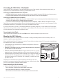
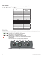
1
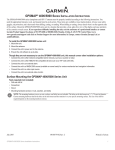
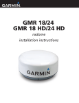
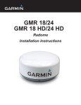
GDL™ 30A XM Weather Data Receiver Installation Instructions
To obtain the best possible performance, install the GDL 30A Weather Data Receiver according to the following instructions. If you experience
difficulty during the installation, contact Garmin Product Support or seek the advice of a professional installer.
Product Registration
Help us better support you by completing our online registration today! Connect to our Web site at http://my.garmin.com. Keep the original
sales receipt, or a photocopy, in a safe place.
Contact Garmin
Contact Garmin if you have any questions while using your GDL 30A. In the USA contact Garmin Product Support by phone:
(913) 397-8200 or (800) 800-1020, or go to www.garmin.com/support/.
In Europe, contact Garmin (Europe) Ltd. at +44 (0) 870.8501241 (outside the UK) or 0808 2380000 (within the UK).
WARNING: See the Important Safety and Product Information guide in the product box for product warnings and other important
information.
Important Numbers
For future reference, write down the important numbers associated with your GDL 30A. The serial number is located on the bottom of the unit.
Serial number
Unique ID numbers are associated with your GDL 30A. XM Satellite Radio™ uses these ID numbers to activate and deactivate your XM
weather and XM audio. To locate the ID numbers on a GPSMAP® 3000 Series chartplotter, refer to the Main Menu section of the GDL
30A Owner’s Manual. To locate the ID numbers on a GPSMAP 4000 or 5000 Series chartplotter, select Configure > System > System
Information.
XM WX Weather™ ID
XM Radio ID
Packing List, Accessories, and Tools Needed
Before installing your unit, check that your package includes the following items. If any parts are missing, contact your Garmin dealer
immediately.
Standard Package
•
•
•
•
•
•
•
GDL 30A unit
7-pin power cable
Garmin Marine Network cable—6 ft. (1.8 m)
Documentation
Audio cable
Grommet
GA 32 Antenna
◦ Surface-mount bracket
◦ Pole-mount bracket
◦ Under-deck mount bracket
◦ Mounting hardware (screws and adhesive pads)
May 2008
Optional Accessories
• GMS 10 network port expander
• Garmin Marine Network cables (20 ft. and 40 ft.)
Tools Needed (Not Included)
•
•
•
•
•
•
•
Drill and drill bits
Fasteners (to mount the GDL 30A)
Hole saw, 1 in. (surface-mount cable hole)
Screwdriver (surface-mount screws)
Center punch and hammer (to mark surface-mount pilot holes)
Countersink bit (when mounting on fiberglass)
Marine sealant (for certain mounting options)
190-00930-02 Rev. B
Printed in Taiwan
Unit Overview
LED status indicator
Power/data connector
Network port
Weather cap
Antenna connector
Mounting holes
Audio connector
Caution: Always wear safety goggles, ear protection, and a dust mask when drilling, cutting, or sanding. When drilling or cutting, always check
what is on the opposite side of the surface.
Mounting the GDL 30A
Mount the GDL 30A in a location that is dry and well ventilated. Avoid mounting the unit where it may become submerged or exposed to
extreme temperatures above 158°F or below 5°F (above 70°C or below -15°C). Verify there is enough clearance to attach the cables to the unit.
Make sure the Status LED is visible to view the blink codes.
To mount the GDL 30A:
1. Using the unit as a template, mark the location of the mounting holes. If needed, additional holes can be drilled in the side mounting flanges.
2. Secure the GDL 30A using fasteners appropriate for the mounting surface.
Connecting the Power Cable
The power cable can be connected directly to the boat battery or through an open connector on the fuse block.
To connect the power cable to a battery:
1. Connect the red wire to the positive (+) terminal of the battery. Do not remove the AGC/3AG 2.0 amp fuse holder from the red wire.
2. Connect the black wire to the negative (-) terminal of the battery.
3. Connect the power cable to the GDL 30A 7-pin connector labeled POWER.
2 A fuse
10–35
VDC
Red
Black
To GDL 30A
Connecting to a Battery
Battery +
Battery -
To connect the power cable to a fuse block:
Connecting to a Fuse Block
1. Remove the AGC/3AG 2.0 A fuse holder from the red wire.
2. Connect the red wire to an open fuse holder in the fuse block. Make sure that the red wire is connected to the positive side of the fuse block.
3. Connect the black wire to the negative side of the fuse block.
4. Install a 2.0 A fuse in the fuse holder.
5. Connect the power cable to the GDL 30A 7-pin connector labeled POWER.
GDL 30A Installation Instructions
Connecting the GDL 30A to a Chartplotter
Connect the GDL 30A to a chartplotter by using the Garmin Marine Network Cable (included). See the installation instructions for your
chartplotter for more detailed information on setting up a Garmin Marine Network.
Connecting to a GPSMAP 4000/5000 series chartplotter:
• A GPSMAP 4000/5000 series chartplotter has three network connectors available. Connect the GDL 30A to any of these connectors.
• If you have multiple chartplotters, connect the GDL 30A to an open connector on any one of the chartplotters.
Connecting to a GPSMAP 3000 series chartplotter:
• A GPSMAP 3000 series chartplotter has one network connector available. If you do not have any other Garmin Marine Network devices,
connect the GDL 30A directly to the GPSMAP 3000 series chartplotter.
• If you need to connect the GDL 30A to multiple GPSMAP 3000 series chartplotters, a GMS 10 Network Port Expander is required.
Garmin does not recommend cutting the Marine Network cable, though cutting the cable may be necessary in certain circumstances. Refer to
the installation instructions for your chartplotter if you need to cut the Marine Network cable.
If you need to drill a hole in your boat, use the included grommet that is specifically designed to cover holes drilled for the Garmin Marine
Network Cable. If a longer cable is needed, contact Garmin or your Garmin dealer. To ensure safety, use tie-wraps, fasteners, and sealant to
secure the cable along a route and through any bulkhead or deck.
Connecting the Audio Cable
Connect the audio cable (included) to the GDL 30A AUDIO connector and to the audio inputs on your stereo receiver.
Mounting the GA 32 Antenna
You can surface mount the GA 32 antenna, attach it to a standard 1 in. OD pipe-threaded-pole marine mount (14 threads-per-inch—not
included), or install the antenna under fiberglass.
Select a suitable location for the GA 32 antenna on your boat. To ensure the best reception, mount the GA 32 antenna in a location that has a
clear, unobstructed view of the sky in all directions.
Better
Best
• Avoid mounting the GA 32 antenna where it is shaded by the superstructure of the boat, a
Good
radome antenna, or mast.
EMI
• Mount the GA 32 antenna at least 3 ft. (1 m) away from (preferably above) the path of
any radar beam or a VHF radio antenna.
EMI (Electromagnetic Interference)
from engine components
• Do not cut or shorten the antenna cable. The length of the antenna cable is set to provide
optimal performance. Shortening the cable adversely effects the performance of the GA 32.
• If additional antenna cable is needed, Garmin recommends a 50-foot cable from Delphi, part Above - best 3 ft. (1 m)
number SA10006. The following adapters are required: BNC plug to SMB jack – available
from Newark, part number 92C7329 and BNC jack to SMB plug – available from Newark,
3 ft.
3 ft. (1 m)
part number 92C7330.
Below - OK
(1 m)
Radar
VHF Radio Antenna
Temporarily secure the antenna in the preferred mounting location and test it for correct
operation. If you experience interference from other electronics, try a different location. When GA 32 Antenna Placement Considerations
you verify correct operation, permanently mount the antenna.
SS BARNETT
Surface mounting the GA 32 Antenna
1. Use the surface-mount bracket as your mounting template.
• Use a center punch to mark the three screw locations on the surface.
• Use a pencil to trace the cable hole in the center of the bracket.
• Set the surface-mount bracket aside. Do not drill through the surface-mount bracket.
GDL 30A Installation Instructions
2. Drill 1/8 in. (3 mm) pilot holes at the three marked locations.
Note: If you are mounting the GA 32 on fiberglass, it is recommended to use a countersink bit to drill a clearance counterbore through the top gelcoat
layer (but no deeper). This will help to avoid cracking in the gelcoat layer when the screws are tightened.
➋
3. Use a 1 in. (25 mm) hole saw to cut the cable hole in the center.
4. Place the seal pad on the bottom of the surface-mount bracket. Make sure that the screw holes align.
5. Use the included M4 screws to attach the surface-mount bracket to the mounting surface.
GA 32
antenna
➊
6. Route the cable through the 1 in. cable hole and connect it to the GA 32.
7. Make sure the large gasket is in place on the bottom of the GA 32 antenna, place
the antenna on the surface-mount bracket ➊, and twist it clockwise to lock it in
place ➋.
Surface-mount
8. Secure the antenna to the mounting bracket with the included M3 set screw ➌.
bracket
Seal
pad
9. Route the cable away from sources of electronic interference, and connect it to your
Mounting
GDL 30A.
Pole Mounting the GA 32 Antenna
➌
Rubber
gasket
surface
With the pole-mount adapter attached to the GA 32 antenna, you can install the antenna
on a standard 1 in. OD pipe-threaded-pole marine mount (14 threads per inch—not
included). You can run the cable through the pole or outside the pole.
To mount the GA 32 with the cable run outside the pole:
1. Route the cable through the pole-mount adapter, and place the cable in the vertical slot along the base of the pole-mount adapter.
2. Thread the pole-mount adapter onto a standard 1 in. OD pipe-threaded-pole marine mount (14 threads per inch—not included). Do not
overtighten the adapter.
3. Connect the cable to the GA 32 antenna.
4. Place the GA 32 antenna on the pole-mount adapter ➊ and twist it clockwise to lock it in place
➋.
5. Secure the antenna to the adapter with the included M3 set screw ➌.
GA 32
6. (Optional) With the GA 32 installed on the pole mount, fill the remaining gap in the vertical
antenna
cable slot with a marine sealant.
7. Attach the marine mount to the boat if it is not already attached.
8. Route the cable away from sources of electronic interference, and connect it to your GDL 30A.
➌
➋
➊
To mount the GA 32 with the cable run through the pole:
1. Position a standard 1 in. OD pipe-threaded-pole marine mount (14 threads per inch—not
included) in the preferred location, and mark the approximate center of the pole.
Pole-mount
2. Drill a 3/4 in. (19 mm) pilot hole for the cable to pass through.
adapter
3. Fasten the marine mount to the boat.
Vertical cable
4. Thread the pole-mount adapter onto the pole. Do not overtighten the adapter.
slot
5. Route the cable through the pole and connect it to the GA 32 antenna.
6. Place the GA 32 antenna on the pole-mount adapter ➊ and twist it clockwise to lock it in place ➋.
7. Secure the antenna to the adapter with the included M3 set screw ➌.
8. (Optional) With the GA 32 installed on the pole mount, fill the vertical cable slot with a marine sealant.
9. Route the cable away from sources of electronic interference, and connect it to your GDL 30A.
GDL 30A Installation Instructions
Under-deck-mounting the GA 32 Antenna
The GA 32 antenna can be mounted under a fiberglass surface with the included adhesive pads. The antenna will not acquire XM satellite
signals through metal—you can only use the under-deck mount under a fiberglass surface.
1. Determine the location on the fiberglass surface where you want to mount the
GA 32 antenna.
2. Place the adhesive pads on the under-deck mounting bracket.
There are holes in the under-deck mounting bracket that can be used to secure
the under-deck mount to the mounting surface with screws. Garmin does not
Mounting
recommend attaching the under-deck mounting bracket to the surface with
surface
screws, because of the likelihood that screws will protrude through the top
of the mounting surface. If you choose to use screws, do so with extreme care. Adhesive pads
GA 32
3. Place the GA 32 antenna in the under-deck mounting bracket.
antenna
4. Adhere the under-deck mounting bracket to the mounting surface.
Under-deck
5. Connect the cable to the GA 32 antenna.
mounting bracket
6. Route the cable away from sources of electronic interference, and connect it to
your GDL 30A.
Connecting the GA 32 to the GDL 30A
Place the GA 32 connector onto the GDL 30A ANTENNA connector and twist clockwise to secure.
Check the antenna’s performance with potentially interfering equipment turned on and off before permanently mounting the antenna. Perform
this test after the XM WX Weather service is activated.
Other electronic equipment, fan motors, the engine ignition system, alternators, generators, radar, and VHF radio transmissions could
potentially cause interference. After proper operation is verified, permanently install the antenna.
Using the GDL 30A
The GDL 30A turns on and off automatically with the Garmin Marine Network to which it is connected. To verify proper operation, turn on the
chartplotter and verify that the Status LED on the front of the GDL 30A is blinking green. For more detail on the blink codes, see page 6.
Subscribing to XM WX Weather and XM Radio
With the GDL 30A installed, contact XM Satellite Radio to activate your XM WX weather and audio subscription service. Follow the
instructions. Complete steps 1–3 BEFORE calling XM Satellite Radio:
Step 1: Check the system setup
Make certain the GDL 30A is fully wired and is connected to a chartplotter. Verify that the GA 32 antenna has been properly installed. If
you own a GDL 30A, verify that the audio cable is connected to your GDL 30A and to your stereo receiver.
Step 2: Turn on your system
Turn on your chartplotter. This automatically turns on the GDL 30A.
Step 3: Identify radio ID(s)
• On a GPSMAP 4000/5000 series chartplotter, from the Home screen, select Configure > System > System Information.
• On a GPSMAP 3000 series chartplotter, press and hold down the ADJ/MENU key. The Main Menu page appears. A list of tabs appears
down the left side of the Menu page. Using the ROCKER key, highlight the XM tab and select the Information subtab.
Record the XM Weather Radio ID and the XM Audio Radio ID. Write these numbers on the front page of these instructions.
Have the ID numbers, your billing address, and other billing information ready when you contact XM Satellite Radio.
Note: To verify that the audio portion functions correctly, on a GPSMAP 4000/5000 series chartplotter, from the Home screen select Configure >
XM Audio. On a GPSMAP 3000 series chartplotter, select the Audio subtab (next to the Information subtab). Verify that XM Preview appears in the
Radio Tuning box.
GDL 30A Installation Instructions
Step 4: Contact XM
Call XM Satellite Radio to activate your weather radio and audio radio subscriptions at (800) 985-9200.
Weather-Related Broadcast Rates
Feature
Broadcast Rate
(minutes)
NEXRAD
Cloud Tops
Storm Cells
Lightning
Wind
Pressure
Hurricanes
Visibility
Fronts
Sea Surface Temperature
Wave Height
Wave Period
Wave Direction
Current Conditions
5
15
1.25
5
12
12
12
12
12
12
12
12
12
12
Forecasts
Sea Surface Conditions
12
12
Blink Codes
The GDL 30A turns on and off when the chartplotter to which it is connected is turned on or off. The two-color (Green/Red) Status LED on the
GDL 30A indicates the current operational status of the module. Codes are:
Green blinking, on for 1 second, off for 1/2 second (slow blink)
Status: GDL 30A is on and is receiving an XM signal.
Red blinking, on for 1/10 second, off for 1/10 second (very fast blink)
Status: System alarm. The chartplotter gives a message indicating the type of failure.
Solid Red (no blink)
Status: Software failure - Call Garmin Product Support at 800-800-1020.
NETWORK
ANTENNA
AUDIO
S TAT U S
Status Indicator LED
GDL 30A Installation Instructions
GDL 30A Specifications
Physical
Size: 4 3/4 in. W × 2 in. H × 6 3/4 in. D (121 mm W × 51 mm H × 172 mm D)
Weight:
1.5 lb. (.680 kg)
Case:Fully gasketed, high-impact plastic and aluminum alloy, waterproof to IEC 60529 IPX7
Temp Range: From 5°F to 158°F ( from -15°C to 70°C)
Power
Source: Usage: Fuse:
10–35 Vdc
18 watts max
AGC/3AG - 2.0 A
Data Output
Source:
Proprietary Garmin data format.
Audio
Output Level:
300 mV rms into 47 kohm
Frequency Response: 10–20,000 Hz, ± 1 dB
Harmonic Distortion: <0.5%
GA 32 Antenna Specifications
Dimensions:
Weight:
Case Material:
Operating Range:
Cable:
Dynamics:
3 19/32 in. (91.6 mm) Diameter × 1 15/16 in. (49.5 mm) High
7.1 oz. (201 g)
Fully gasketed, high-impact plastic alloy, waterproof to IEC 529 IPX7 standards
From -40°F to 176°F (from -40°C to 80°C)
Foil-shielded, center conductor 18 AWG
999 knots, 40g
Note: When using the chartplotter and GDL 30A on battery power only (engines off) for extended periods of time, be sure there is enough available
amperage to run the units for the time period. Running other onboard devices at the same time may lower the available amperage, causing the
chartplotter and/or GDL 30A to shut off. Check with your local marine dealer/installer if problems persist.
GDL 30A Installation Instructions
© 2008 Garmin Ltd. or its subsidiaries
All rights reserved. Except as expressly provided herein, no part of this manual may be reproduced, copied, transmitted, disseminated, downloaded or stored in any storage
medium, for any purpose without the express prior written consent of Garmin. Garmin hereby grants permission to download a single copy of this manual onto a hard drive or
other electronic storage medium to be viewed and to print one copy of this manual or of any revision hereto, provided that such electronic or printed copy of this manual must
contain the complete text of this copyright notice and provided further that any unauthorized commercial distribution of this manual or any revision hereto is strictly prohibited.
Information in this document is subject to change without notice. Garmin reserves the right to change or improve its products and to make changes in the content without
obligation to notify any person or organization of such changes or improvements. Visit the Garmin Web site (www.garmin.com) for current updates and supplemental
information concerning the use and operation of this and other Garmin products.
Garmin® and GPSMAP® are trademarks of Garmin Ltd. or its subsidiaries, registered in the USA and other countries. GDL 30A, GA 32, and myGarmin™ are trademarks of
Garmin Ltd. or its subsidiaries. These trademarks may not be used without the express permission of Garmin.
For the latest free software updates (excluding map data) throughout the life of your
Garmin products, visit the Garmin Web site at www.garmin.com.
© 2008 Garmin Ltd. or its subsidiaries
Garmin International, Inc.
1200 East 151st Street, Olathe, Kansas 66062, USA
Garmin (Europe) Ltd.
Liberty House, Hounsdown Business Park, Southampton, Hampshire, SO40 9RB UK
Garmin Corporation
No. 68, Jangshu 2nd Road, Shijr, Taipei County, Taiwan
www.garmin.com
Part Number 190-00930-02 Rev. B