1
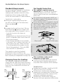
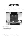
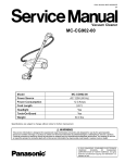
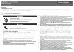
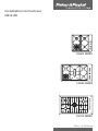
Installation Instructions
NZ & AU
CG602 SERIES
CG902 SERIES
CG913 SERIES
599257 A 01.2005 NZ & AU
Safety & Warnings
WARNING
Cut Hazard
Beware of sharp
edges when handling
stainless steel
appliances.
Failure to use caution
could result in injury
or cuts.
WARNINGS!
Particular attention shall be given to
the relevant requirements regarding
ventilation.
This product should not be sealed into
the bench with silicone or glue. Doing
so will make future servicing difficult.
Fisher & Paykel will not be liable for costs
associated with releasing such a product,
nor for repairing damage that may be
incurred in doing this.
When this product is installed it shall not
be used as a space heater, especially if
installed in boats or caravans.
No combustible material or products
should be placed on this product at any
time.
Do not spray aerosols in the vicinity of
this product while it is in operation.
CAUTION!
This product must be installed according
to these installation instructions and must
comply with local building regulations,
local gas authority codes and electrical
regulations.
Failure to install the product correctly could
invalidate any warranty or liability claims.
2
IMPORTANT!
Read these instructions carefully before
installing or using this product.
Please make this information available to the
person responsible for installing the product
as it could reduce your installation costs.
These products are registered:
in New Zealand at www.ess.govt.nz and
in Australia with AGA at www.gas.asn.au.
Before You Start
Prior to installation, ensure that the local
distribution conditions (nature of gas and
pressure) and the adjustment of the product
are compatible. For adjustment conditions
for this product see Gas Rate Summary.
This gas hob must be connected to a
220V - 240V 50Hz power supply only and
must be earthed via the power cord.
Ensure a suitable disconnection switch
is incorporated in the permanent wiring,
mounted and positioned to comply with
the local wiring rules and regulations. A
means of disconnection with at least a
3 mm air gap contact separation in all poles
must be incorporated into the fixed wiring in
accordance with the wiring rules, unless the
local wiring rules allow for alternative means.
Ensure that there is a power outlet within
reach of the cooktop cable (900 mm from
the rear right of the product). This must be
accessible after installation. The mains cable
should not touch any metal parts.
Make the bench top of a heat resistant
material.
Seal exposed bare edges of the cutout
with an oil-based paint or moisture proof
polyurethane to prevent possible damage
from moisture creeping between the
cooktop trim and the benchtop.
Dimensions
A
B
C
J
F
manifold
centre line
H
gas inlet
E
G
D
Product
A Width
B Depth
C Height
Pan support
to Benchtop
Cutout
D Width
E Depth
F Radius
G
H
J
Clearance to nearest
combustible service
CG602 series
CG902 series
CG913 series
578
914
914
511
533
546
40
40
76
43 (52 Wok)
43 (52 Wok)
22
CG602 series
CG902 series
CG913 series
560 (558-562)
870 (846-872)
870 (860-882)
490 (485-495)
494 (478-501)
494 (486-524)
R10
R10
R10
30
30
30
40
50
35
60
60
81
Note:
All measurements given in millimetres (mm).
Cutout dimensions are given as an ‘ideal measurement’ e.g. for new cutouts, followed by an
‘otherwise acceptable range’ (in brackets) e.g. for existing cutouts or replacement products.
3
Clearances
a
b
d
e
g
f
c
a 600 mm minimum from top of trivet to rangehood.
750 mm minimum from top of trivet to overhead exhaust fan. (Fisher & Paykel splashbacks are
750 mm high).
b 600 mm minimum from top of trivet to downward facing combustable surface.
(450 mm
minimum if protected by tiles or fire resistant materials).
CG602 SERIES
CG902 SERIES
CG913 SERIES
130 mm
120 mm
80 mm
100 mm
90 mm
90 mm
Clearance from rear edge of
product to any non-combustible
surface
10 mm
10 mm
10 mm
e Clearance below benchtop to any
60 mm
60 mm
81 mm
45 mm
45 mm
81 mm
c Clearance from side edge of
product to any combustible surface
d Clearance from rear edge of
product to any combustible surface
combustible surface
Clearance below benchtop to
F&P DishDrawer® or F&P oven
f
Ensure there is an earthed power outlet within 900 mm of the rear right-hand corner of the
product. When used with a flexible hose, the connector on the wall should be between 800
mm to 850 mm above the floor and in the region outside the width of the appliance to a
distance of 250 mm. This should be accessible with the appliance installed.
g When protecting a wall with non-combustible material it must be at least 150 mm high.
4
Installation Instructions
Gas Supply Connection
Australian and New Zealand Gas Installation
Standards (AS5601, NZS 5261) require a
cooktop to be installed so that the surface
temperature of any nearby combustible
surface will not exceed 65oC above ambient.
This cooktop is supplied set up for
Natural Gas but is suitable for installation
with either Natural Gas or LPG. Refer to
relevant table for pressures and appropriate
orifice sizes.
OR
B by protecting the wall, to at least 150 mm
high [Dimension g] along it’s length, with
non-combustible surface materials, such as:
- 5 mm thick ceramic tiles alone are
adequate.
- Tempered glass or sheetmetal (min. 0.4 mm
thick) is acceptable when used in front of a
fire resistant material.
- Fisher & Paykel Splashback (not available
in Australia): This is stainless steel with a 10
mm air gap to the wall. When used with
a 10 mm gap behind the product to the
front of the splashback. (Only with SB90
series and SB1216 splashbacks.)
These products meet the Standards
requirements when installed to the
dimensions in these Instructions. (They have
been tested by an Independent Testing Lab).
Clamping Down the Cooktop
This cooktop is supplied with fastening
clamps that will cope with a bench thickness
of 20-50 mm. For benchtops thicker than 50
mm, recess the underside to a thickness of
20-50 mm.
50 mm
20 mm
recessed to
50 mm
Gas connection to the product MUST use
the elbow supplied. The regulator will not
seal if installed without it.
Ensure the blue washer (supplied) is located
between the elbow (supplied) and product
inlet as below. Failure to use this washer
will cause the product to leak. Tighten the
floating nut to firm finger tight, plus an
additional 1/4 turn (90o).
Blue washer
Elbow (1/2” BSP male)
CG913 series
Typically this is achieved by:
A Having the cooktop spaced away from
the wall (see “Clearances” for dimensions)
[Dimension c and d]
CG602, CG902 series
Standards Requirements
Gas Inlet (1/2” BSP internal thread)
After installation, make sure all
connections are gas tight.
A duplicate data plate enclosed inside the
accessories pack should be placed on an
accessible surface adjacent to the cooktop.
Flexible Hoses
Flexible hose assemblies should be AS/NZS
1869 Class B or Class D certified.
Flexible hoses should not be exposed to
temperatures exceeding their certified value.
They should not touch hot surfaces on the
cooktop or neighbouring products.
Flexible hoses should not be subject to
abrasion, kinking or permanent deformation.
5
Installation Instructions
Natural Gas
For Natural Gas usage the gas supply is
connected to the regulator which is supplied
loose with a built in test point - 1kPa (4” WG)
and the inlet connection of 1/2 “ B.S.P. (male
thread). Do not over tighten.
The operation of the appliance, including
the ignition system, must be tested
before installation is complete.
If after following the instructions given,
satisfactory performance cannot be
obtained, contact the local gas authority
or your local Approved Service Agent for
advice and assistance.
The test point pressure should be preset
to 1.0 kPa with the wok and semi - rapid
burners operating at maximum.
Conversion to Different Gas Type
Burners can be used with NG or LPG,
provided that the orifices appropriate for the
gas supply are installed.
To change the orifices, you will need a 7 mm
box spanner (and a 10 mm ring spanner for
CG913TM).
LP Gas
For LPG usage the gas supply for the
appliance must be regulated to a pressure
of 2.75kPa (11” WG). See ‘Conversion to a
different gas type’ .
1
Turn off the main electrical supply.
Gas Supply Connection Check
WARNING!
The connection point shall be accessible
with the appliance installed.
To enable the gas supply to be readily shut
off, the gas supply must be connected with
an isolating valve close to the product.
After installation and making all connections
check thoroughly for possible leaks.
Electrical Shock Hazard.
Disconnect product from main power
supply before continuing.
2
3
4
5
1 Turn all control knobs on the unit to “off”
position.
2 Open the valve on the gas supply.
3 Using a suitable leak detection fluid solution
(e.g. Rocol) check each gas connection one
at a time by brushing the solution over the
connection.
Ensure all gas valves are turned off.
Remove all trivets and burner heads.
Pull off knobs.
Unscrew the orifices and replace them
with the correct ones. (size numbers are
stamped on the side, eg. 70= 0.70 mm)
(see figure 1)
6
Remove the 2 screws holding each burner
(3 on the wok burner).
7
Lift hob tray from the product.
Tighten the fitting and recheck for leaks.
Ensure the washer (supplied) is located
between elbow and product gas inlet.
5 Turn on each gas valve and light each
burner.
6 Check for a clear blue flame without yellow
tipping. If burners show any abnormalities,
check that they are located and assembled
properly. Check correct orifices are installed.
CG913TM only
4 The presence of bubbles will indicate a leak.
WARNING!
Cut Hazard.
Beware of sharp edges.
8
Replace the wok orifice with the correct
one using a 10 mm spanner.
9
Reset the venturi (see fig.2). Loosen the
venturi screw, move the venturi toward the
orifice approx. 2 mm.
10 To refit the CG913 series hob tray, repeat
steps 6 and 7 in reverse.
11 Check insulation resistance and earth
continuity.
6
continued...
Installation Instructions
12 Turn on main electrical supply and light the
Minimum Setting or Turn Down
burners.
13 Important!
This has been set at the factory for NG but
may need adjusting for local conditions.
14 Check all burners have good flame (see
When converting to LPG, the minimum
setting MUST be reset for each burner.
Reset the minimum setting
(see ‘Minimum Setting or Turndown’).
fig.3,4,5).
To adjust the minimum setting you will need
a Ø 2.5 x 45 mm screwdriver.
Venturi
figure 1
figure 3
figure 2
figure 4
1
Ignite the burner and set the knob to its
minimum position.
2
3
Remove the knob.
4
5
Replace the knob.
Rotate the turn down screw slowly until
a minimum regular flame is achieved.
(The flame will diminish when the screw
is turned clockwise and increase when
turned anti-clockwise (see fig.6).
When the setting is right check regulation
by quickly rotating the knob from the
maximum to the minimum delivery
position. The flame must not go out.
figure 5
Note: CG913TM models may require
progressive venturi adjustment on the wok
burner:
Fig.3 Lifting Off - move the venturi closer to
the orifice.
Fig.4 Yellow Tipping - move the venturi
away from the orifice.
Fig.5 Good Flame.
The label supplied with the orifices should
be placed over the existing gas type label
located on the underside of the product to
indicate the gas change.
figure 6
7
Installation Instructions
Gas Rate Summary
Burners
Natural Gas
Orifice size MJ/h@1 kPa
LPG
Orifice size MJ/[email protected] kPa
CG602
Auxiliary Burner (RH front)
0.85 mm
3.6 MJ/h
0.55 mm
3.9 MJ/h
Semi-Rapid Burner (LH & RH rear)
1.3 mm
8.5 MJ/h
0.8 mm
8.4 MJ/h
Wok Burner (LF front)
1.8 mm
15 MJ/h
1.05 mm
15 MJ/h
Rapid Burner (LH front)
1.55 mm
12 MJ/h
1.00 mm
13 MJ/h
Auxiliary Burner (RH front)
0.85 mm
3.7 MJ/h
0.55 mm
4.1 MJ/h
Semi-Rapid Burner (LH & RH rear)
1.3 mm
7.9 MJ/h
0.80 mm
7.9 MJ/h
Fish Burner (Centre)
1.45 mm
10 MJ/h
0.85 mm
10 MJ/h
Wok Burner (LH front)
1.8 mm
15 MJ/h
1.05 mm
15 MJ/h
CG902
GC913T
Simmer Burner (RH front)
0.85 mm
3.6 MJ/h
0.45 mm
2.7 MJ/h
Semi-Rapid Burner (LH rear)
1.22 mm
7.2 MJ/h
0.7 mm
6.2 MJ/h
Rapid Burner (LH front & RH rear)
1.45 mm
10.5 MJ/h
0.85 mm
9.3 MJ/h
Wok Burner (Centre)
1.80 mm
15.5 MJ/h
1.05 mm
14.5 MJ/h
Simmer Burner (RH front)
0.85 mm
3.6 MJ/h
0.45 mm
2.7 MJ/h
Semi-Rapid Burner (LH rear)
1.22 mm
7.2 MJ/h
0.7 mm
6.2 MJ/h
Rapid Burner (LH front & RH rear)
1.45 mm
10.5 MJ/h
0.85 mm
9.3 MJ/h
Wok Burner (Centre)
1.90 mm
16.3 MJ/h
1.10 mm
15.3 MJ/h
CG913TM
Customer Care
Current Information
New Zealand
P.O. Box 58732, Greenmount, Auckland.
Toll Free 0800 FP CARE (0800 37 2273)
Fax
09 273 0656
Email [email protected]
Current Installation Instructions, Product
dimensions and specifications are available
on the Fisher & Paykel web site:
Australia
P.O. Box 798, Cleveland, QLD 4163.
Toll Free 1300 650 590
Tel
07 3826 9100
Fax
07 3826 9298
Email [email protected]
8
www.fisherpaykel.com