1
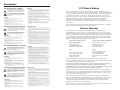
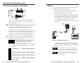
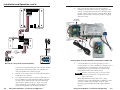
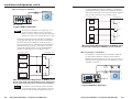
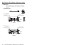
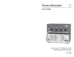
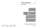
User’s Manual
SCREEN POSITION
DOWN
STOP
UP
RCM-SC
ROOM CONTROL
SCREEN POSITION
LIGHTING
ON / OFF
RCM-SCLT
Relay Control Modules
Control Accessories
www.extron.com
Extron Electronics, USA
Extron Electronics, Europe
Extron Electronics, Asia
Extron Electronics, Japan
1230 South Lewis Street
Anaheim, CA 92805
USA
714.491.1500
Fax 714.491.1517
Beeldschermweg 6C
3821 AH Amersfoort
The Netherlands
+31.33.453.4040
Fax +31.33.453.4050
135 Joo Seng Road, #04-01
PM Industrial Building
Singapore 368363
+65.6383.4400
Fax +65.6383.4664
Daisan DMJ Building 6F
3-9-1 Kudan Minami
Chiyoda-ku, Tokyo 102-0074 Japan
+81.3.3511.7655
Fax +81.3.3511.7656
© 2002 Extron Electronics. All rights reserved.
68-631-01
Printed in the USA
Precautions
Safety Instructions • English
This symbol is intended to alert the user of important
operating and maintenance (servicing) instructions
in the literature provided with the equipment.
This symbol is intended to alert the user of the
presence of uninsulated dangerous voltage within
the product's enclosure that may present a risk of
electric shock.
Caution
Read Instructions • Read and understand all safety and operating
instructions before using the equipment.
Retain Instructions • The safety instructions should be kept for future
reference.
Follow Warnings • Follow all warnings and instructions marked on the
equipment or in the user information.
Avoid Attachments • Do not use tools or attachments that are not
recommended by the equipment manufacturer because they may be
hazardous.
Consignes de Sécurité • Français
Ce symbole sert à avertir l’utilisateur que la
documentation fournie avec le matériel contient des
instructions importantes concernant l’exploitation
et la maintenance (réparation).
Ce symbole sert à avertir l’utilisateur de la présence
dans le boîtier de l’appareil de tensions dangereuses
non isolées posant des risques d’électrocution.
Attention
Lire les instructions• Prendre connaissance de toutes les consignes de
sécurité et d’exploitation avant d’utiliser le matériel.
Conserver les instructions• Ranger les consignes de sécurité afin de
pouvoir les consulter à l’avenir.
Respecter les avertissements • Observer tous les avertissements et
consignes marqués sur le matériel ou présentés dans la documentation
utilisateur.
Eviter les pièces de fixation • Ne pas utiliser de pièces de fixation ni
d’outils non recommandés par le fabricant du matériel car cela
risquerait de poser certains dangers.
Sicherheitsanleitungen • Deutsch
Dieses Symbol soll dem Benutzer in der im
Lieferumfang enthaltenen Dokumentation
besonders wichtige Hinweise zur Bedienung und
Wartung (Instandhaltung) geben.
Dieses Symbol soll den Benutzer darauf aufmerksam
machen, daß im Inneren des Gehäuses dieses
Produktes gefährliche Spannungen, die nicht isoliert
sind und die einen elektrischen Schock verursachen
können, herrschen.
Achtung
Lesen der Anleitungen • Bevor Sie das Gerät zum ersten Mal verwenden,
sollten Sie alle Sicherheits-und Bedienungsanleitungen genau
durchlesen und verstehen.
Aufbewahren der Anleitungen • Die Hinweise zur elektrischen Sicherheit
des Produktes sollten Sie aufbewahren, damit Sie im Bedarfsfall darauf
zurückgreifen können.
Befolgen der Warnhinweise • Befolgen Sie alle Warnhinweise und
Anleitungen auf dem Gerät oder in der Benutzerdokumentation.
Keine Zusatzgeräte • Verwenden Sie keine Werkzeuge oder Zusatzgeräte,
die nicht ausdrücklich vom Hersteller empfohlen wurden, da diese eine
Gefahrenquelle darstellen können.
Instrucciones de seguridad • Español
Este símbolo se utiliza para advertir al usuario sobre
instrucciones importantes de operación y
mantenimiento (o cambio de partes) que se desean
destacar en el contenido de la documentación
suministrada con los equipos.
Este símbolo se utiliza para advertir al usuario sobre
la presencia de elementos con voltaje peligroso sin
protección aislante, que puedan encontrarse dentro
de la caja o alojamiento del producto, y que puedan
representar riesgo de electrocución.
Precaucion
Leer las instrucciones • Leer y analizar todas las instrucciones de
operación y seguridad, antes de usar el equipo.
Conservar las instrucciones • Conservar las instrucciones de seguridad
para futura consulta.
Obedecer las advertencias • Todas las advertencias e instrucciones
marcadas en el equipo o en la documentación del usuario, deben ser
obedecidas.
Evitar el uso de accesorios • No usar herramientas o accesorios que no
sean especificamente recomendados por el fabricante, ya que podrian
implicar riesgos.
FCC Class A Notice
Warning
Power sources • This equipment should be operated only from the power source
indicated on the product. This equipment is intended to be used with a main
power system with a grounded (neutral) conductor. The third (grounding) pin is
a safety feature, do not attempt to bypass or disable it.
Power disconnection • To remove power from the equipment safely, remove all
power cords from the rear of the equipment, or the desktop power module (if
detachable), or from the power source receptacle (wall plug).
Power cord protection • Power cords should be routed so that they are not likely to
be stepped on or pinched by items placed upon or against them.
Servicing • Refer all servicing to qualified service personnel. There are no userserviceable parts inside. To prevent the risk of shock, do not attempt to service
this equipment yourself because opening or removing covers may expose you to
dangerous voltage or other hazards.
Slots and openings • If the equipment has slots or holes in the enclosure, these are
provided to prevent overheating of sensitive components inside. These openings
must never be blocked by other objects.
Lithium battery • There is a danger of explosion if battery is incorrectly replaced.
Replace it only with the same or equivalent type recommended by the
manufacturer. Dispose of used batteries according to the manufacturer's
instructions.
Note: This equipment has been tested and found to comply with the limits for a
Class A digital device, pursuant to part 15 of the FCC Rules. These limits are designed
to provide reasonable protection against harmful interference when the equipment is
operated in a commercial environment. This equipment generates, uses and can
radiate radio frequency energy and, if not installed and used in accordance with the
instruction manual, may cause harmful interference to radio communications.
Operation of this equipment in a residential area is likely to cause harmful
interference, in which case the user will be required to correct the interference at his
own expense.
Note: This unit was tested with shielded cables on the peripheral devices. Shielded
cables must be used with the unit to ensure compliance.
Avertissement
Alimentations• Ne faire fonctionner ce matériel qu’avec la source d’alimentation
indiquée sur l’appareil. Ce matériel doit être utilisé avec une alimentation
principale comportant un fil de terre (neutre). Le troisième contact (de mise à la
terre) constitue un dispositif de sécurité : n’essayez pas de la contourner ni de la
désactiver.
Déconnexion de l’alimentation• Pour mettre le matériel hors tension sans danger,
déconnectez tous les cordons d’alimentation de l’arrière de l’appareil ou du
module d’alimentation de bureau (s’il est amovible) ou encore de la prise secteur.
Protection du cordon d’alimentation • Acheminer les cordons d’alimentation de
manière à ce que personne ne risque de marcher dessus et à ce qu’ils ne soient
pas écrasés ou pincés par des objets.
Réparation-maintenance • Faire exécuter toutes les interventions de réparationmaintenance par un technicien qualifié. Aucun des éléments internes ne peut être
réparé par l’utilisateur. Afin d’éviter tout danger d’électrocution, l’utilisateur ne
doit pas essayer de procéder lui-même à ces opérations car l’ouverture ou le
retrait des couvercles risquent de l’exposer à de hautes tensions et autres dangers.
Fentes et orifices • Si le boîtier de l’appareil comporte des fentes ou des orifices,
ceux-ci servent à empêcher les composants internes sensibles de surchauffer. Ces
ouvertures ne doivent jamais être bloquées par des objets.
Lithium Batterie • Il a danger d'explosion s'll y a remplacment incorrect de la
batterie. Remplacer uniquement avec une batterie du meme type ou d'un ype
equivalent recommande par le constructeur. Mettre au reut les batteries usagees
conformement aux instructions du fabricant.
Vorsicht
Stromquellen • Dieses Gerät sollte nur über die auf dem Produkt angegebene
Stromquelle betrieben werden. Dieses Gerät wurde für eine Verwendung mit
einer Hauptstromleitung mit einem geerdeten (neutralen) Leiter konzipiert. Der
dritte Kontakt ist für einen Erdanschluß, und stellt eine Sicherheitsfunktion dar.
Diese sollte nicht umgangen oder außer Betrieb gesetzt werden.
Stromunterbrechung • Um das Gerät auf sichere Weise vom Netz zu trennen,
sollten Sie alle Netzkabel aus der Rückseite des Gerätes, aus der externen
Stomversorgung (falls dies möglich ist) oder aus der Wandsteckdose ziehen.
Schutz des Netzkabels • Netzkabel sollten stets so verlegt werden, daß sie nicht
im Weg liegen und niemand darauf treten kann oder Objekte darauf- oder
unmittelbar dagegengestellt werden können.
Wartung • Alle Wartungsmaßnahmen sollten nur von qualifiziertem
Servicepersonal durchgeführt werden. Die internen Komponenten des Gerätes
sind wartungsfrei. Zur Vermeidung eines elektrischen Schocks versuchen Sie in
keinem Fall, dieses Gerät selbst öffnen, da beim Entfernen der Abdeckungen die
Gefahr eines elektrischen Schlags und/oder andere Gefahren bestehen.
Schlitze und Öffnungen • Wenn das Gerät Schlitze oder Löcher im Gehäuse
aufweist, dienen diese zur Vermeidung einer Überhitzung der empfindlichen
Teile im Inneren. Diese Öffnungen dürfen niemals von anderen Objekten
blockiert werden.
Litium-Batterie • Explosionsgefahr, falls die Batterie nicht richtig ersetzt wird.
Ersetzen Sie verbrauchte Batterien nur durch den gleichen oder einen
vergleichbaren Batterietyp, der auch vom Hersteller empfohlen wird. Entsorgen
Sie verbrauchte Batterien bitte gemäß den Herstelleranweisungen.
Advertencia
Alimentación eléctrica • Este equipo debe conectarse únicamente a la fuente/tipo
de alimentación eléctrica indicada en el mismo. La alimentación eléctrica de este
equipo debe provenir de un sistema de distribución general con conductor
neutro a tierra. La tercera pata (puesta a tierra) es una medida de seguridad, no
puentearia ni eliminaria.
Desconexión de alimentación eléctrica • Para desconectar con seguridad la
acometida de alimentación eléctrica al equipo, desenchufar todos los cables de
alimentación en el panel trasero del equipo, o desenchufar el módulo de
alimentación (si fuera independiente), o desenchufar el cable del receptáculo de
la pared.
Protección del cables de alimentación • Los cables de alimentación eléctrica se
deben instalar en lugares donde no sean pisados ni apretados por objetos que se
puedan apoyar sobre ellos.
Reparaciones/mantenimiento • Solicitar siempre los servicios técnicos de personal
calificado. En el interior no hay partes a las que el usuario deba acceder. Para
evitar riesgo de electrocución, no intentar personalmente la reparación/
mantenimiento de este equipo, ya que al abrir o extraer las tapas puede quedar
expuesto a voltajes peligrosos u otros riesgos.
Ranuras y aberturas • Si el equipo posee ranuras o orificios en su caja/alojamiento,
es para evitar el sobrecalientamiento de componentes internos sensibles. Estas
aberturas nunca se deben obstruir con otros objetos.
Batería de litio • Existe riesgo de explosión si esta batería se coloca en la posición
incorrecta. Cambiar esta batería únicamente con el mismo tipo (o su equivalente)
recomendado por el fabricante. Desachar las baterías usadas siguiendo las
instrucciones del fabricante.
Extron’s Warranty
Extron Electronics warrants this product against defects in materials and
workmanship for a period of three years from the date of purchase. In the event of
malfunction during the warranty period attributable directly to faulty workmanship
and/or materials, Extron Electronics will, at its option, repair or replace said products
or components, to whatever extent it shall deem necessary to restore said product to
proper operating condition, provided that it is returned within the warranty period,
with proof of purchase and description of malfunction to:
USA, Canada, South America,
and Central America:
Extron Electronics
1230 South Lewis Street
Anaheim, CA 92805, USA
Asia:
Extron Electronics, Asia
135 Joo Seng Road, #04-01
PM Industrial Bldg.
Singapore 368363
Europe, Africa, and the Middle East:
Extron Electronics, Europe
Beeldschermweg 6C
3821 AH Amersfoort
The Netherlands
Japan:
Extron Electronics, Japan
Daisan DMJ Bldg. 6F,
3-9-1 Kudan Minami
Chiyoda-ku, Tokyo 102-0074
Japan
This Limited Warranty does not apply if the fault has been caused by misuse,
improper handling care, electrical or mechanical abuse, abnormal operating conditions
or non-Extron authorized modification to the product.
If it has been determined that the product is defective, please call Extron and ask for
an Applications Engineer at (714) 491-1500 (USA), 31.33.453.4040 (Europe),
65.6383.4400 (Asia), or 81.3.3511.7655 (Japan) to receive an RA# (Return Authorization
number). This will begin the repair process as quickly as possible.
Units must be returned insured, with shipping charges prepaid. If not insured, you
assume the risk of loss or damage during shipment. Returned units must include the
serial number and a description of the problem, as well as the name of the person to
contact in case there are any questions.
Extron Electronics makes no further warranties either expressed or implied with
respect to the product and its quality, performance, merchantability, or fitness for any
particular use. In no event will Extron Electronics be liable for direct, indirect, or
consequential damages resulting from any defect in this product even if Extron
Electronics has been advised of such damage.
Please note that laws vary from state to state and country to country, and that some
provisions of this warranty may not apply to you.
Table of Contents
Chapter 1 • Introduction .......................................................... 1-1
About the Relay Control Modules ................................. 1-2
Features ...................................................................................... 1-2
Chapter 2 • Installation and Operation ......................... 2-1
Installation Overview .......................................................... 2-2
UL Requirements .................................................................... 2-3
Rear Panel Connectors and Switches .......................... 2-4
Cabling ........................................................................................ 2-5
MLC relay wiring for an RCM-SC .......................................... 2-8
MLC relay wiring for an RCM-SCLT ....................................... 2-9
Front Panel Features and Operation ......................... 2-13
Setting Up the Buttons ..................................................... 2-13
Testing/Troubleshooting .................................................. 2-15
Mounting the Control Module Into an
AAP Wallplate or Device Faceplate ............................ 2-16
Appendix A • Specifications, Part Numbers,
Accessories, and Dimensions ............................................... A-1
Specifications ......................................................................... A-2
Included Parts ......................................................................... A-3
Accessories ............................................................................... A-3
Cables ......................................................................................... A-3
Dimensions .............................................................................. A-4
All trademarks mentioned in this manual are the properties of their respective owners.
68-631-01 Rev. A
Printed in the USA
01 02
Relay Control Modules • Table of Contents
i
Table of Contents, cont’d
Relay Control Modules
1
Chapter One
Introduction
About the Relay Control Modules
Features
ii
Relay Control Modules • Table of Contents
Introduction
About the Relay Control Modules
The Extron Relay Control Modules (RCMs) are hard-wired
remote control keypads designed for use with the Extron
MediaLink Controller (MLC). Refer to the MediaLink Controllers
User’s Manual for information on installing, operating, and
setting up the controller.
All setup must be done via RS-232. See chapter two and
refer to the MediaLink Control Program or the
MediaLink Controllers User’s Manual for details.
Each control module fits into a double-space high area (1.4” H x
3.5” W) in an Extron Architectural Adapter Plate, interface, or
distribution amplifier.
The relay control modules toggle relays within a MediaLink
Controller to operate controls for various items in a room (such
as a screen control or a light switch). The RCM-SC controls the
movement of a projection screen. The RCM-SCLT controls up/
down screen movement and also lighting. In this manual Relay
Control Modules are referred to as “modules”, “RCMs”, or
“control modules” when instructions apply to more than one
model.
Features
Grey, black, or white faceplates — The control modules are
offered in three shades for integration into a variety of
environments.
System expandability — Up to four control modules (RCMs,
infrared control modules/IRCMs, audio control modules/
ACMs) can be daisy chained together in any combination
and connected to a MediaLink Controller to provide basic
A/V source and room control from several locations.
Furniture and wall mountability — The control modules can be
mounted onto or in furniture or walls if they are installed
in optional mounting plates (AAP 102, AAP 104) or in the
MediaLink Controller’s accessory faceplates.
Relay Control Modules
2
Chapter Two
Installation and Operation
Installation Overview
UL Requirements
Rear Panel Connectors and Switches
Cabling
Front Panel Features and Operation
Testing/Troubleshooting
1-2
Relay Control Modules • Introduction
Installation and Operation
Installation Overview
CAUTION
Installation and service must be performed by
authorized personnel only. These products should
be used with UL approved electrical boxes. See
“UL Requirements”, page 2-3.
To install and set up Relay Control Modules, follow these steps:
1
Turn the equipment off. Make sure that the control
module(s) and the MediaLink Controller (MLC) are
disconnected from the power source.
2
Run cables through the wall or furniture where the control
module(s) will be installed.
3
If applicable, follow the site preparation (hole cutting,
electrical box or mud ring/mounting bracket installation,
and cable preparation) instructions included with the
device, faceplate, or AAP wall plate into which the control
module will be installed. Cable clamps should be used to
hold the cables in place for strain relief. Trim back and/or
insulate exposed cable shields with heat shrink to reduce
the chance of short circuits.
4
2-2
Attach the control module(s) to the Extron faceplate(s) or
AAP wall plate(s).
5
Set the identification DIP switches on each control
module’s circuit board.
6
Connect daisy-chained control modules to each other (if
applicable). Wire the 3.5 mm, 5-pole captive screw
connectors on both ends of each cable that will connect
one control module to another. Plug the wired connectors
into the receptacles on the back of the control modules.
7
Connect the control module(s) to the MLC. At the control
module end of the cable, wire the connector that will
attach the MLC to the control module(s). Plug the wired
connector into the receptacles on the back of the control
module(s), and insert and fasten the wires to the
appropriate pins of the MLS/Power port on the bottom of
the MLC.
8
Connect the projector’s RS-232 port to the MLC’s Display/
Source Control RS-232 port (refer to the MediaLink
Controllers User’s Manual). If infrared control modules
(IRCMs) are part of the system, connect IR Emitters or an
IR Broadcaster to the MLC’s Display/Source Control IR
port.
Relay Control Modules • Installation and Operation
9
Connect a MediaLink Switcher (MLS) to the MLC 206 and
to the projector, if applicable.
10
Restore power to the MLC, and connect the optional MLS
switcher to a power supply.
11
Set up the MLC.
The setup/configuration requires an RS-232 connection
to the MLC’s Config port. Setup should be done before
the MLC is installed into the wall or furniture.
12
Press a button on each control module. If the expected
action (a lighting or screen position change, for example)
doesn’t occur, disconnect power from the MLC and verify
correct connector wiring at both ends of the cable(s).
13
Mount the MLC and the faceplate/wallplate containing
the control module(s) into the wall/furniture. Make sure
that the faceplate is grounded.
UL Requirements
1.
These units are not to be connected to a centralized DC
power source or used beyond their rated voltage range.
2.
These units must be installed in UL listed junction boxes.
The UL approved electrical wall box (junction box) is not
included with the control module; the installer is
responsible for obtaining and installing the box.
3.
These units must be installed with accordance with the
National Electrical Code and with local electrical codes.
Relay Control Modules • Installation and Operation
2-3
Installation and Operation, cont’d
Rear Panel Connectors and Switches
For each control module to be connected to an MLC, set the rear
panel DIP switches, then follow these steps:
1
1
A B C D E
A B C D E
1 2
ON
2
The same type and quantity of connectors and DIP switches
shown above can be found on the rear panels of all models of
the control modules.
1
Cabling
1.
If it hasn’t already been done when the wall box was
installed, cut a length of Extron Comm-Link cable to go
between the MLC and the control module.
2.
Using the following diagram as a guide, attach a 3.5 mm,
5-pole captive screw connector to the end of the cable that
will be plugged into the control module, and connect wires
on the other end of the cable to the MLC’s IR/RCM port (a
4-pole direct insertion captive screw connector).
Wire both ends of the cable identically (pin A to pin A, pin
B to pin B, etc.).
Control
Module
connector
Communications connectors — Use these connectors to connect
control modules together and to connect them to the MLC and
to an optional IR Link infrared repeater. Both connectors
function the same way, so they are interchangeable.
ABCD E
RCM Control
Module(s)
ROOM CONTROL
SCREEN POSITION
LIGHTING
ON / OFF
Plug one end of an Extron Comm-Link cable into one of these
3.5 mm, 5-pole captive screw connectors, and plug the other end
into a connector on another control module or an IR Link, or
connect those wires to the direct insertion IR/RCM captive screw
connector of an MLC. Do not install more than one IR Link.
2
DIP switches — Set these switches to identify the address of
each module. Each module must have a unique address. Note
the direction of the arrow on the switch.
ON
1 2
ON
1 2 3 4
Address DIP switches can be 4-position or
2-position, but only 1 and 2 are used.
1, 2 — Control module address identification — See the following illustrations for the appropriate settings for each address.
3, 4 — Not used
ON
1 and 2 down (off)
=
address 0, control module #1
1 2
A
A
+12VDC
Ground ( )
B
B
C Control signal (RCM/ C
IRCM)
DISPLAY
POWER
MLC
IR / RCM
port
VCR
DVD
Laptop
VOLUME
MAX/
MIN
Extron
A B C D
MLC 206
MediaLink Controller
IR / RCM
MLC 206
MLC 206 to a Relay Control Module
Only three wires are required, but use four wires (A, B, C, D)
if an IR Link infrared repeater will be daisy chained with
the control modules. Refer to the IR Link User’s Manual for
details.
Do not install more than one IR Link in a MediaLink
system. Also, do not connect more than four control
modules (RCMs, ACMs, IRCMs) at a time to an MLC.
ON
1 up (on), 2 down (off) = address 1, control module #2
1 2
ON
1 down (off), 2 up (on) = address 2, control module #3
The MLC contains three relays, so you may install a
maximum of one RCM-SC or one RCM-SCLT in a
system with an MLC.
1 2
ON
1 up (on), 2 up (on)
= address 3, control module #4
1 2
DIP switch settings
2-4
Relay Control Modules • Installation and Operation
Relay Control Modules • Installation and Operation
2-5
Installation and Operation, cont’d
5.
A B C D E
A B C D E
Plug one end of the cable into the control module’s
remaining communications connector, and plug the other
end into a communications connector on the next control
module. The photo below shows control modules (RCM,
IRCMs, and/or ACMs) connected to an MLC in a typical
daisy chain setup.
To 1–2 additional
Control Modules
(IRCMs, ACMs, RCMs)
Control Module #2
rear view
MLM faceplate
MLC 206 rear view
Control Module
To an
MLS
switcher
A
B
C
Control Module
DVD CONTROL
Tx
MENU
Control Module #1
rear view
TITLE
A B C D E
A B C D E
ENTER
REW
PLAY
NEXT
PAUSE
RS-232
projector
connection
STOP
Control
Module
1 2
ON
ROOM CONTROL
SCREEN POSITION
LIGHTING
ON / OFF
MLC
IR / RCM
port
IR Emitter
RCM
Control
Module
A
A
+12VDC
Ground ( )
B
B
C Control signal (RCM/ C
IRCM)
(Connect 1 per
each IRCM.)
IR Link Infrared Repeater
rear view
DISPLAY
POWER
VCR
DVD
Laptop
VOLUME
MAX/
MIN
A daisy chain of control modules connected to an MLC 206
A B C D
IR / RCM
Extron
MLC 206
MediaLink Controller
MLC 206 to a daisy chain of Control Modules
MLC 206
Connectors are included with each control module, but the
cable must be purchased separately. See appendix A for
cable part numbers and conductor gauges.
2-6
3.
Plug the 5-pole connector into one of the control module’s
communications connectors.
4.
Cut a cable and attach 5-pole connectors to both ends of it
for each additional control module that will be connected
in a daisy chain. Wire both ends of the cable identically
(pin A to pin A, pin B to pin B, etc.). Up to a total of 4
control modules in any combination of models can be
daisy chained together and connected to the MLC.
Relay Control Modules • Installation and Operation
6.
Connect the MLC’s rear/bottom panel relay ports to a
screen controller or a relay controller (A/C trigger box) if it
is appropriate for your installation. Use the following
block diagrams as a general reference, and refer to the
wiring diagrams that came with the screen.
The MLC contains three relays, so you may install a
maximum of one RCM-SC or one RCM-SCLT in a
system with an MLC.
Many different brands and models of low voltage
controllers can be used with the MLC and RCM to control
screen movement. A few examples are given on the
following pages, but different models require different
wiring.
Relay Control Modules • Installation and Operation
2-7
Installation and Operation, cont’d
MLC relay wiring for an RCM-SC
For Stewart Filmscreen screen controllers, a momentary
closure between the up and common terminals, the down
and common terminals, or the stop and common terminals
will cause the screen to go up, go down, or stop.
Low Voltage
Controller
Stop
Low Voltage Controller
SCREEN POSITION
DISPLAY
POWER
DOWN
VCR
DVD
STOP
UP
MLC Relay Ports
Laptop
VOLUME
UNSWITCHED
MAX/
RCM-SC
MIN
1A
Up
100-240V - 5AMAX
Extron
Up
MLC 206
MediaLink Controller
1B
MLC 206 w/ AAP
A typical RCM-SC application
The diagrams included here are examples only. Your
equipment may have different wiring requirements.
Refer to the specific wiring instructions provided by the
manufacturer of the screen controller that you are using.
For DaLite and Draper screen controllers, a momentary
closure between either the up and common terminals or
the down and common terminals causes the screen to
move up or move down. A momentary closure between
all three terminals (up, down, and common) stops the
screen in its current position. Use the included diodes
(1N4001 or equivalent) for reverse bias protection.
Low Voltage Controller
2A
Down
MLC Relay Ports
3A
Stop
Stop
3B
Common
MLC relay wiring block diagram for an RCM-SC and a
Stewart SFC Control (part #6300891) screen controller
MLC relay wiring for an RCM-SCLT
For controllers, a momentary closure between either the
up and common terminals or the down and common
terminals causes the screen to move up or move down. A
latching contact toggles the AC power/lighting (or other)
controller on and off.
1A
Red
Up
1B
2A
Black
Down
2B
Down
AC Power
Controller
2B
3A
White (Da Lite)
Blue (Draper)
Low Voltage
Controller
Stop
3B
ROOM CONTROL
DISPLAY
POWER
SCREEN POSITION
VCR
DVD
Laptop
VOLUME
LIGHTING
ON / OFF
UNSWITCHED
MAX/
RCM-SC LT
MIN
MLC relay wiring block diagram for an RCM-SC and a
Da Lite single motor LVC-4 (part #40973) screen controller or a
Draper single motor LVCIII screen controller (part #6300858)
Use 1N4001 or equivalent diodes (100mA maximum
current through the diode, 50V maximum reverse bias)
for the Da Lite and Draper installations shown above.
2-8
Relay Control Modules • Installation and Operation
100-240V - 5AMAX
Extron
MLC 206
MediaLink Controller
MLC 206 w/ AAP
A typical RCM-SCLT application
Relay Control Modules • Installation and Operation
2-9
Installation and Operation, cont’d
The diagrams included here are examples only. Your
equipment may have different wiring requirements.
Refer to the specific wiring instructions provided by the
manufacturer of the screen controller and AC power
controller that you are using.
Low Voltage Controller
Red
(Da Lite/Draper)
Up (Stewart)
The following two illustrations give examples of how to
connect a relay controller to the MLC to turn lights or
another device on and off. Refer to the manual that came
with the controller for specific wiring information for
the equipment you are using.
MLC Relay Ports
1A
1 2 3 4
Up
AC1
1B
Black
(Da Lite/Draper)
Down (Stewart)
OFF
ON
2A
Down
2B
CONTROL
1 2 3 4
White (Da Lite)
Blue (Draper)
110 VAC/1200W
110 VAC
50/60 HZ
Common (Stewart)
3A
AC Power Controller
3A
3B
12VDC
3B
Common
MLC relay wiring block diagram for an RCM-SCLT
and a Da Lite (#40973), Draper (#6300858), or
Stewart (#6300891) screen controller and a relay
controller
2-10
Relay Control Modules • Installation and Operation
MLC Relay Port
Connecting an AMX PC-1 AC power controller to
the MLC for lighting control
The AMX PC-1 relay box can be configured for momentary
or latching operation. All front panel DIP switches should
be in the down position for latching mode operation. See
AMX’s instructions if you need to change modes. Also set
the MLC’s relay to “latching” and “normally open”.
Relay Control Modules • Installation and Operation
2-11
Installation and Operation, cont’d
Front Panel Features and Operation
120 VAC 50/60 Hz
MAX LOAD 15 A
SCREEN POSITION
DOWN
ROOM CONTROL
STOP
UP
SCREEN POSITION
LIGHTING
C
ON / OFF
LISTED
7Z37
PROFESSIONAL
AUDIO EQUIPMENT
MINIPORT-15
POWER RELAY
CLASS2 WIRING
+12VDC
6Ma MAX
STATUS REM GND
POWER
DELAY
OUT
3A
RCM-SC
Front
1
2
1
1
3
RCM-SCLT
Front
1
Screen Position Up ( )/Down ( ) buttons — These buttons can
be set up (via the control software) to toggle the screen to move
up or down.
2
Screen Position Stop button — Press this button to stop the
up/down motion of the screen.
3
Lighting On/Off button — This button acts like a light switch,
toggling the room lights on or off when pressed. This button
must also be set up via the control software before it can control
the lights.
3B
MLC Relay Port
Connecting a Furman MiniPort-15 AC power
controller to the MLC for lighting control
For the Furman controller, connect pins 3A and 3B of the
MLC’s relay port to the 12VDC and REM poles. The relay
should be set for latching connection, and the MLC
contacts should be set to “normally open”.
7.
Use the MediaLink Control Software to set up the modules
and the relays. See “Setting Up the Buttons” in this
chapter for details.
Setting Up the Buttons
Before the control module’s buttons can control the MLC’s
relays, you must set up the MLC for each of the RCM’s buttons.
Refer to the MediaLink Control Program for specific details.
1.
Cable and supply power to the MLC, the control
module(s), and a host computer.
2.
Start the Windows-based MediaLink Control Program.
3.
In the Controller (MLC) Configuration section of the
program, select (click on) the control module button that
you wish to set up, and select (click on) the box
corresponding to the relay you want to tie to that button.
Assign the appropriate relay to each RCM button in the
Controller (MLC) Config section of the software. In the
Relay & Misc. Options section of the software, set all the
relays to NO (normally open). Also set the relays used for
screen control to momentary contact, and set relays used for
lighting control to latching contact.
2-12
Relay Control Modules • Installation and Operation
Relay Control Modules • Installation and Operation
2-13
Installation and Operation, cont’d
Testing/Troubleshooting
Before installing the control modules into the wall or furniture,
test the system to make sure that the connections are correct and
the modules are working correctly.
4.
6.
Connect the cables between the MLC and the control
module(s), connect IR Emitters or an IR Broadcaster to the
MLC (if IRCM modules are used), and connect a host
computer to the MLC’s Config port. If available, cable the
A/V source device(s) to the display device (projector), and
connect the projector and any relay-controllable items to
the MLC. Refer the MediaLink Controller User’s Manual for
wiring diagrams.
2.
Connect the MLC to a 12VDC power source. Connect the
host computer, A/V source device(s), and projector to a
power source and turn them on.
3.
Start the MediaLink Control Program, and set up the
control modules and the MLC (for each button set up the
relays, select or type in RS-232 commands, or perform IR
learning).
4.
Press the buttons on the control module, watch the
module’s LED (for IRCM and ACM modules), and observe
the item being controlled by the module (lights, screen,
projector mount, VCR, DVD, MLS switcher, etc.).
In the Relay & Misc. Options portion of the control
program, select the appropriate options for each relay.
For example, set the relays that are tied to the Screen
Position Up ( ), Screen Position Down ( ), and Stop
buttons to Momentary, and select the duration for the
momentary contact. For the relay that is tied to the
Lighting On/Off button (RCM-SCLT only), select Latched.
5.
1.
Set each relay to (NO) Open (normally open). Refer to the
MediaLink Controllers User’s Manual and the MediaLink
Control Program for more information.
Repeat steps 3, 4, and 5 for each RCM button.
The MLC contains three relays, so you may install a
maximum of one RCM-SC or one RCM-SCLT in a
system with an MLC.
4A
If the LED does not light when a button is pressed,
check the captive screw connector wiring at both the
MLC and the control module. If the conductor
assignments are not the same at both ends, the
circuits may be damaged if power is applied to the
wrong pole, and the control module will not turn on.
Verify that the connectors are wired identically at
both ends of the cable.
4B
If power is present at the MLC and at the control
module, but the item being controlled does not
respond when a button is pressed:
• Make sure the control module’s address DIP
switch settings are correct and that each module
has a unique address.
• For IRCM and CM modules, check the MediaLink
control software to verify that an IR command
has been “learned” for that button.
• For IRCM and CM modules, verify that an IR
Emitter or IR Broadcaster has been connected to
the MLC’s Display/Source Control IR connector.
2-14
Relay Control Modules • Installation and Operation
Relay Control Modules • Installation and Operation
2-15
Installation and Operation, cont’d
All IR control signals are sent to all devices (video
sources, projector, etc.) at the same time even if two or
three IR Emitters or an IR Broadcaster are installed. The
IR sending devices share the same IR Display/Control
port on the MLC.
• For RCM modules, ensure that the wiring from
the MLC to the screen motor’s low voltage
controller is correct. Refer to the screen
manufacturer’s user’s guides. For the
RCM-SCLT, ensure that the wiring from the MLC
to the AC power controller is correct for the
model you are using.
5.
Call the Extron S3 Sales and Technical Support Hotline if
the item(s) being controlled still does (do) not respond
when the control module’s buttons are pressed.
Mounting the Control Module Into an AAP
Wallplate or Device Faceplate
The control module and any other adapter plates must be
attached to a device faceplate or AAP wallplate and cabled
before the device or wallplate is installed in a wall or furniture.
The screws needed for installing the control module are built
into its front panel, so no additional screws will be needed.
1.
Before any cables are attached, insert the control module’s
screws through the holes in the device’s faceplate or AAP
wallplate. Secure the control module to the faceplate/
wallplate with the provided captive washers and #4-40
nuts.
2.
Follow steps 5 through
section of this chapter.
3.
If the control module is not installed into a grounded metal wall
box, ground the faceplate before fastening the faceplate
into the wall or furniture.
12
A
Appendix A
Specifications, Part Numbers,
Accessories, and Dimensions
in the “Installation Overview”
Do not tie a module’s faceplate to both a separate earth
ground and the circuit ground (via a connector pin). If
you tie a product to two different ground sources, you
may introduce ground loops or other grounding-related
problems into the system.
2-16
Relay Control Modules
Relay Control Modules • Installation and Operation
Specifications
Included Parts
Accessories
Cables
Dimensions
Specifications, Part #s, Accessories, Dimensions
Specifications
Included Parts
These items are included in each order for a control module:
General
Power ............................................. 12VDC from the MLC 206
Temperature/humidity .............. Storage -40° to +158°F (-40° to +70°C) /
10% to 90%, non-condensing
Operating +32° to +122°F (0° to +50°C) /
10% to 90%, non-condensing
Rack mount ................................... Yes, with optional faceplate, and
furniture/wall mountable with optional
faceplates or AAP wall plates
Enclosure type .............................. Metal
Enclosure dimensions
Faceplate ................... 1.4" H x 3.5" W x 0.1” D (3.5 cm H x 8.9
cm W x 0.3 cm D) (double space high AAP
plate)
Boards ........................ 1.3" H x 2.6" W x 0.9" D
(3.3 cm H x 6.6 cm W x 2.3 cm D)
(Depth excludes buttons. Allow at least
2.1” (5.3 cm) depth in the wall/furniture.)
Product weight ............................. 0.1 lbs (<0.1 kg)
Shipping weight ........................... 1 lbs (0.5 kg)
Vibration ....................................... ISTA/NSTA 1A in carton (International
Safe Transit Association)
Listings .......................................... UL, CUL as components of the MLC 206
Compliances ................................. CE, FCC Class A, VCCI, AS/NZS, ICES as
components of the MLC 206
MTBF ............................................. 30,000 hours
Warranty ....................................... 3 years parts and labor
Included parts
or
Part number
RCM-SC (grey, black, white)
70-183-01, -02, -03
RCM-SCLT (grey, black, white)
70-184-01, -02, -03
3.5 mm, 5-pole captive screw connectors
10-319-10
1N4001 or equivalent diodes
(100mA max. current, 50V max. reverse bias)
for Da Lite and Draper installations
Relay Control Modules User’s Manual
68-631-01
Accessories
Accessories
Part number
AAP 102 (grey, black, white) (2 gang)
60-300-01, -02, -03
AAP 104 (grey, black, white) (4 gang)
60-301-01, -02, -03
Cables
Comm-link cable
Part number
50 feet/15.2 meters long
26-461-01
100 feet/30.5 meters long
26-461-02
Specifications are subject to change without notice.
(7.32-112601-D1)
Conductor gauges in Extron Comm-Link cables
red and black single strands (for power/ground)
18 AWG
white and violet shielded single strands (for signals) 22 AWG
drain wire
A-2
Relay Control Modules • Specifications, Part #s, Dimensions
24 AWG
Relay Control Modules • Specifications, Part #s, Dimensions
A-3
Specifications, Part Numbers, Accessories, cont’d
Dimensions
The following diagrams have been reduced to fit on the page.
All dimensions are given in inches. The symbol “ø“ indicates a
diameter.
RCM dimensions
.363
.182
.160
DETAIL A
+.000/
Ø.160-.010 max. extrusion around
stud on far side,
+.003/
+.003/
Ø.112-.000 thru (4 places).
Ø.166-.000 thru (2 places).
PEM insert BSOS-440-16 or
equiv. Insert from near side.
2.900
PEM insert FHS-440-6 or equiv.
Insert from near side. (4 req'd)
+.000
1.390-.015
1.195
1.045
0.695
DETAIL A
0.345
0.195
0.000
3.500
3.250
2.786
1.750
0.600
0.714
0.250
0.000
(5 PLCS)
R.050
(4 PLCS)
RCM-SC
+.000/
Ø.160-.010 max. extrusion around
stud on far side,
+.003/
+.003/
Ø.112-.000 thru (4 places).
Ø.166-.000 thru (2 places).
PEM insert BSOS-440-16 or
equiv. Insert from near side.
2.900
PEM insert FHS-440-6 or equiv.
Insert from near side. (4 req'd)
+.000
1.390-.015
1.195
1.045
0.695
DETAIL A
0.345
0.195
0.000
3.500
3.250
2.786
1.232
0.714
0.600
0.250
0.000
(5 PLCS)
R.050
(4 PLCS)
RCM-SCLT
A-4
.320
Relay Control Modules • Specifications, Part #s, Dimensions