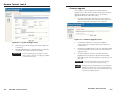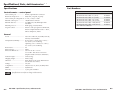
1
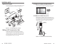
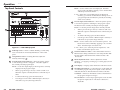
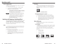
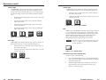
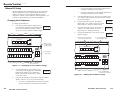
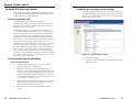
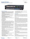
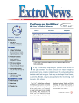
User’s Manual
RCP 2000
Remote Control Panel
www.extron.com
Extron Electronics, USA
Extron Electronics, Europe
Extron Electronics, Asia
Extron Electronics, Japan
1230 South Lewis Street
Anaheim, CA 92805
USA
714.491.1500
Fax 714.491.1517
Beeldschermweg 6C
3821 AH Amersfoort
The Netherlands
+31.33.453.4040
Fax +31.33.453.4050
135 Joo Seng Road, #04-01
PM Industrial Building
Singapore 368363
+65.6383.4400
Fax +65.6383.4664
Kyodo Building
16 Ichibancho
Chiyoda-ku, Tokyo 102-0082 Japan
+81.3.3511.7655
Fax +81.3.3511.7656
© 2005 Extron Electronics. All rights reserved.
68-792-01 Rev. C
03 05
FCC Class A Notice
Precautions
Safety Instructions • English
This symbol is intended to alert the user of important
operating and maintenance (servicing) instructions
in the literature provided with the equipment.
This symbol is intended to alert the user of the
presence of uninsulated dangerous voltage within
the product's enclosure that may present a risk of
electric shock.
Caution
Read Instructions • Read and understand all safety and operating
instructions before using the equipment.
Retain Instructions • The safety instructions should be kept for future
reference.
Follow Warnings • Follow all warnings and instructions marked on the
equipment or in the user information.
Avoid Attachments • Do not use tools or attachments that are not
recommended by the equipment manufacturer because they may be
hazardous.
Consignes de Sécurité • Français
Ce symbole sert à avertir l’utilisateur que la
documentation fournie avec le matériel contient des
instructions importantes concernant l’exploitation
et la maintenance (réparation).
Ce symbole sert à avertir l’utilisateur de la présence
dans le boîtier de l’appareil de tensions dangereuses
non isolées posant des risques d’électrocution.
Attention
Lire les instructions• Prendre connaissance de toutes les consignes de
sécurité et d’exploitation avant d’utiliser le matériel.
Conserver les instructions• Ranger les consignes de sécurité afin de
pouvoir les consulter à l’avenir.
Respecter les avertissements • Observer tous les avertissements et
consignes marqués sur le matériel ou présentés dans la documentation
utilisateur.
Eviter les pièces de fixation • Ne pas utiliser de pièces de fixation ni
d’outils non recommandés par le fabricant du matériel car cela
risquerait de poser certains dangers.
Sicherheitsanleitungen • Deutsch
Dieses Symbol soll dem Benutzer in der im
Lieferumfang enthaltenen Dokumentation
besonders wichtige Hinweise zur Bedienung und
Wartung (Instandhaltung) geben.
Dieses Symbol soll den Benutzer darauf aufmerksam
machen, daß im Inneren des Gehäuses dieses
Produktes gefährliche Spannungen, die nicht isoliert
sind und die einen elektrischen Schock verursachen
können, herrschen.
Achtung
Lesen der Anleitungen • Bevor Sie das Gerät zum ersten Mal verwenden,
sollten Sie alle Sicherheits-und Bedienungsanleitungen genau
durchlesen und verstehen.
Aufbewahren der Anleitungen • Die Hinweise zur elektrischen Sicherheit
des Produktes sollten Sie aufbewahren, damit Sie im Bedarfsfall darauf
zurückgreifen können.
Befolgen der Warnhinweise • Befolgen Sie alle Warnhinweise und
Anleitungen auf dem Gerät oder in der Benutzerdokumentation.
Keine Zusatzgeräte • Verwenden Sie keine Werkzeuge oder Zusatzgeräte,
die nicht ausdrücklich vom Hersteller empfohlen wurden, da diese eine
Gefahrenquelle darstellen können.
Instrucciones de seguridad • Español
Este símbolo se utiliza para advertir al usuario sobre
instrucciones importantes de operación y
mantenimiento (o cambio de partes) que se desean
destacar en el contenido de la documentación
suministrada con los equipos.
Este símbolo se utiliza para advertir al usuario sobre
la presencia de elementos con voltaje peligroso sin
protección aislante, que puedan encontrarse dentro
de la caja o alojamiento del producto, y que puedan
representar riesgo de electrocución.
Precaucion
Leer las instrucciones • Leer y analizar todas las instrucciones de
operación y seguridad, antes de usar el equipo.
Conservar las instrucciones • Conservar las instrucciones de seguridad
para futura consulta.
Obedecer las advertencias • Todas las advertencias e instrucciones
marcadas en el equipo o en la documentación del usuario, deben ser
obedecidas.
Evitar el uso de accesorios • No usar herramientas o accesorios que no
sean especificamente recomendados por el fabricante, ya que podrian
implicar riesgos.
Warning
Power sources • This equipment should be operated only from the power source
indicated on the product. This equipment is intended to be used with a main
power system with a grounded (neutral) conductor. The third (grounding) pin is
a safety feature, do not attempt to bypass or disable it.
Power disconnection • To remove power from the equipment safely, remove all
power cords from the rear of the equipment, or the desktop power module (if
detachable), or from the power source receptacle (wall plug).
Power cord protection • Power cords should be routed so that they are not likely to
be stepped on or pinched by items placed upon or against them.
Servicing • Refer all servicing to qualified service personnel. There are no userserviceable parts inside. To prevent the risk of shock, do not attempt to service
this equipment yourself because opening or removing covers may expose you to
dangerous voltage or other hazards.
Slots and openings • If the equipment has slots or holes in the enclosure, these are
provided to prevent overheating of sensitive components inside. These openings
must never be blocked by other objects.
Lithium battery • There is a danger of explosion if battery is incorrectly replaced.
Replace it only with the same or equivalent type recommended by the
manufacturer. Dispose of used batteries according to the manufacturer's
instructions.
Avertissement
Alimentations• Ne faire fonctionner ce matériel qu’avec la source d’alimentation
indiquée sur l’appareil. Ce matériel doit être utilisé avec une alimentation
principale comportant un fil de terre (neutre). Le troisième contact (de mise à la
terre) constitue un dispositif de sécurité : n’essayez pas de la contourner ni de la
désactiver.
Déconnexion de l’alimentation• Pour mettre le matériel hors tension sans danger,
déconnectez tous les cordons d’alimentation de l’arrière de l’appareil ou du
module d’alimentation de bureau (s’il est amovible) ou encore de la prise secteur.
Protection du cordon d’alimentation • Acheminer les cordons d’alimentation de
manière à ce que personne ne risque de marcher dessus et à ce qu’ils ne soient
pas écrasés ou pincés par des objets.
Réparation-maintenance • Faire exécuter toutes les interventions de réparationmaintenance par un technicien qualifié. Aucun des éléments internes ne peut être
réparé par l’utilisateur. Afin d’éviter tout danger d’électrocution, l’utilisateur ne
doit pas essayer de procéder lui-même à ces opérations car l’ouverture ou le
retrait des couvercles risquent de l’exposer à de hautes tensions et autres dangers.
Fentes et orifices • Si le boîtier de l’appareil comporte des fentes ou des orifices,
ceux-ci servent à empêcher les composants internes sensibles de surchauffer. Ces
ouvertures ne doivent jamais être bloquées par des objets.
Lithium Batterie • Il a danger d'explosion s'll y a remplacment incorrect de la
batterie. Remplacer uniquement avec une batterie du meme type ou d'un ype
equivalent recommande par le constructeur. Mettre au reut les batteries usagees
conformement aux instructions du fabricant.
Vorsicht
Stromquellen • Dieses Gerät sollte nur über die auf dem Produkt angegebene
Stromquelle betrieben werden. Dieses Gerät wurde für eine Verwendung mit
einer Hauptstromleitung mit einem geerdeten (neutralen) Leiter konzipiert. Der
dritte Kontakt ist für einen Erdanschluß, und stellt eine Sicherheitsfunktion dar.
Diese sollte nicht umgangen oder außer Betrieb gesetzt werden.
Stromunterbrechung • Um das Gerät auf sichere Weise vom Netz zu trennen,
sollten Sie alle Netzkabel aus der Rückseite des Gerätes, aus der externen
Stomversorgung (falls dies möglich ist) oder aus der Wandsteckdose ziehen.
Schutz des Netzkabels • Netzkabel sollten stets so verlegt werden, daß sie nicht
im Weg liegen und niemand darauf treten kann oder Objekte darauf- oder
unmittelbar dagegengestellt werden können.
Wartung • Alle Wartungsmaßnahmen sollten nur von qualifiziertem
Servicepersonal durchgeführt werden. Die internen Komponenten des Gerätes
sind wartungsfrei. Zur Vermeidung eines elektrischen Schocks versuchen Sie in
keinem Fall, dieses Gerät selbst öffnen, da beim Entfernen der Abdeckungen die
Gefahr eines elektrischen Schlags und/oder andere Gefahren bestehen.
Schlitze und Öffnungen • Wenn das Gerät Schlitze oder Löcher im Gehäuse
aufweist, dienen diese zur Vermeidung einer Überhitzung der empfindlichen
Teile im Inneren. Diese Öffnungen dürfen niemals von anderen Objekten
blockiert werden.
Litium-Batterie • Explosionsgefahr, falls die Batterie nicht richtig ersetzt wird.
Ersetzen Sie verbrauchte Batterien nur durch den gleichen oder einen
vergleichbaren Batterietyp, der auch vom Hersteller empfohlen wird. Entsorgen
Sie verbrauchte Batterien bitte gemäß den Herstelleranweisungen.
Advertencia
Alimentación eléctrica • Este equipo debe conectarse únicamente a la fuente/tipo
de alimentación eléctrica indicada en el mismo. La alimentación eléctrica de este
equipo debe provenir de un sistema de distribución general con conductor
neutro a tierra. La tercera pata (puesta a tierra) es una medida de seguridad, no
puentearia ni eliminaria.
Desconexión de alimentación eléctrica • Para desconectar con seguridad la
acometida de alimentación eléctrica al equipo, desenchufar todos los cables de
alimentación en el panel trasero del equipo, o desenchufar el módulo de
alimentación (si fuera independiente), o desenchufar el cable del receptáculo de
la pared.
Protección del cables de alimentación • Los cables de alimentación eléctrica se
deben instalar en lugares donde no sean pisados ni apretados por objetos que se
puedan apoyar sobre ellos.
Reparaciones/mantenimiento • Solicitar siempre los servicios técnicos de personal
calificado. En el interior no hay partes a las que el usuario deba acceder. Para
evitar riesgo de electrocución, no intentar personalmente la reparación/
mantenimiento de este equipo, ya que al abrir o extraer las tapas puede quedar
expuesto a voltajes peligrosos u otros riesgos.
Ranuras y aberturas • Si el equipo posee ranuras o orificios en su caja/alojamiento,
es para evitar el sobrecalientamiento de componentes internos sensibles. Estas
aberturas nunca se deben obstruir con otros objetos.
Batería de litio • Existe riesgo de explosión si esta batería se coloca en la posición
incorrecta. Cambiar esta batería únicamente con el mismo tipo (o su equivalente)
recomendado por el fabricante. Desachar las baterías usadas siguiendo las
instrucciones del fabricante.
Note: This equipment has been tested and found to comply with the limits for a
Class A digital device, pursuant to part 15 of the FCC Rules. These limits are
designed to provide reasonable protection against harmful interference when the
equipment is operated in a commercial environment. This equipment generates,
uses and can radiate radio frequency energy and, if not installed and used in
accordance with the instruction manual, may cause harmful interference to radio
communications. Operation of this equipment in a residential area is likely to
cause harmful interference, in which case the user will be required to correct the
interference at his own expense.
Note: This unit was tested with shielded cables on the peripheral devices.
Shielded cables must be used with the unit to ensure compliance.
Extron’s Warranty
Extron Electronics warrants this product against defects in materials and
workmanship for a period of three years from the date of purchase. In the event of
malfunction during the warranty period attributable directly to faulty
workmanship and/or materials, Extron Electronics will, at its option, repair or
replace said products or components, to whatever extent it shall deem necessary to
restore said product to proper operating condition, provided that it is returned
within the warranty period, with proof of purchase and description of malfunction
to:
USA, Canada, South America,
and Central America:
Europe, Africa, and the Middle East:
Extron Electronics
1001 East Ball Road
Anaheim, CA 92805, USA
Extron Electronics, Europe
Beeldschermweg 6C
3821 AH Amersfoort
The Netherlands
Asia:
Japan:
Extron Electronics, Asia
135 Joo Seng Road, #04-01
PM Industrial Bldg.
Singapore 368363
Extron Electronics, Japan
Kyodo Building
16 Ichibancho
Chiyoda-ku, Tokyo 102-0082
Japan
This Limited Warranty does not apply if the fault has been caused by misuse,
improper handling care, electrical or mechanical abuse, abnormal operating
conditions or non-Extron authorized modification to the product.
If it has been determined that the product is defective, please call Extron and ask
for an Applications Engineer at (714) 491-1500 (USA), 31.33.453.4040 (Europe),
65.6383.4400 (Asia), or 81.3.3511.7655 (Japan) to receive an RA# (Return
Authorization number). This will begin the repair process as quickly as possible.
Units must be returned insured, with shipping charges prepaid. If not insured,
you assume the risk of loss or damage during shipment. Returned units must
include the serial number and a description of the problem, as well as the name of
the person to contact in case there are any questions.
Extron Electronics makes no further warranties either expressed or implied with
respect to the product and its quality, performance, merchantability, or fitness for
any particular use. In no event will Extron Electronics be liable for direct, indirect,
or consequential damages resulting from any defect in this product even if Extron
Electronics has been advised of such damage.
Please note that laws vary from state to state and country to country, and that
some provisions of this warranty may not apply to you.
Quick Start Guide — RCP 2000
Step 1
Turn the equipment off and disconnect it from the power source.
Make sure that the ISS 108/408 or SGS 408 and all attached devices
are turned off and, if applicable, disconnected from the power
source.
Step 2
Set the RCP 2000 on a table or other flat surface.
Step 3
SGS Switcher:
Attach one of the RS-232 cables provided with the RCP 2000 between
the RS-232 Remote port on the rear panel of the SGS and the
To Switcher port on the rear panel of the RCP 2000.
ISS Switcher:
Attach one of the RS-232 cables provided with the RCP 2000 between
the RS-232 port on the rear panel of the ISS and the To Switcher port
on the rear panel of the RCP 2000; or attach a network cable between
the ISS and RCP 2000 rear panel Ethernet ports.
Preview
Monitor
Program
Monitor
Projector
Extron
ISS 408
RAM
PROG
S VIEW
PUTPRE
OUT
M
GRA
R
PRO
DVI
OUT
System
Control
IEW
PREV
R
G
2
RS-23
G
B
Seamless Switcher
B
8
H/HV
7
RNET
ETHE
LINK
ACT
R
H/HV
6
V
R
TS 5
INPU
V
R
G
4
R
G
3
R
G
B
2
R
G
B
1
R
G
R
B
G
B
G
H/HV
H/HV
B
G
H/HV
B
H/HV
B
H/HV
8
B
H/HV
7
6
H/HV
Hz
5
50/60
240 MAX.
100- 1.2A
H/HV
4
3
2
1
DVD Player
H
RE
TU
PIC
LS
RO
T
NT
CON HT
CO
OR
COL
TINT
E
WIP
BRIG
IL
DETA
CUT
E
FAD
SIZE
CEN
TER
R
ME
DIM
OG
PR
Codec
CK
BLA
Extron
RGB 109xi
Interface
VCR
1
2
3
4
EZE
FRE
COM
5
2
1
CK
BLA
EZE
FRE
RA
M
6
3
7
4
8
5
9
7
6
PR
11
10
EV
8
12
9
OLVE
DISS
12
11
10
IEW
ION
ICAT
MUNTx
Rx
Extron
RCP 2000
Remote Control Panel
Laptop
Podium PC
RCP 2000 to ISS connection diagram
RCP 2000 • Quick Start Guide
QS-1
Quick Start Guide — RCP 2000, cont’d
Six sizes of male-to-male RS-232 cables are provided with the
RCP 2000, any of which can be used to connect the SGA or
ISS switcher’s RS-232 port to the RCP 2000’s To Switcher
(RS-232) port. If you require a length of cable other than what
is provided, you can make your own communication cable (see
Making an RCP Communication Cable in chapter 2).
Additionally, you can connect the RCP 2000 to the ISS via
Ethernet using a network cable (not provided).
Step 4
Continue the procedure for installing the ISS 108/408 or SGS 408.
Step 5
Attach power cords and plug the ISS or SGS seamless switcher, the
input devices, and the output devices into a grounded AC source.
Attach the power cord to the RCP 2000.
Step 6
Select an input using the RCP 2000 top panel (Program input)
buttons. The image should now appear.
Step 7
If the image does not appear, do the following:
• Ensure that all devices are plugged in and receiving power.
• Check the cabling and make adjustments as needed.
• Select a different input to check for an image.
Table of Contents
Chapter 1 • Introduction .......................................................... 1-1
Features ...................................................................................... 1-2
Chapter 2 • Installation ............................................................ 2-1
Rear Panel Connectors ........................................................ 2-2
Installation ................................................................................ 2-2
Application Example ............................................................ 2-4
Making an RCP Communication Cable ....................... 2-4
RCP 2000 to ISS 108/408, SGS 408 RS-232 link ..................... 2-5
RCP 2000 to ISS 108/408 Ethernet link ................................. 2-5
Chapter 3 • Operation ................................................................ 3-1
Top Panel Controls ................................................................. 3-2
Using the Picture Controls ................................................ 3-5
Adjusting color and tint ........................................................ 3-5
Adjusting contrast and brightness ....................................... 3-5
Sizing an image ..................................................................... 3-5
Centering an image ............................................................... 3-5
Detail adjustments ................................................................. 3-6
Applying and Changing a Switching Effect ............. 3-6
Cuts ......................................................................................... 3-6
Dissolves ................................................................................. 3-7
Changing the duration of a dissolve .............................. 3-7
Wipes (SGS only) .................................................................... 3-7
Standard wipe .................................................................. 3-7
Curtain wipe ..................................................................... 3-8
Plus wipe .......................................................................... 3-8
Square wipe ..................................................................... 3-9
Title ................................................................................... 3-9
Selecting a wipe and a wipe duration ............................ 3-9
Implementing an effect ...................................................... 3-10
Implementing a title ............................................................ 3-11
Resetting the Unit ............................................................... 3-11
Chapter 4 • Remote Control .................................................. 4-1
Manual IP Setup ..................................................................... 4-2
Changing the IP addresses .................................................... 4-2
Network IP Setup and Control ........................................ 4-4
Contacting the RCP unit ........................................................ 4-4
QS-2
RCP 2000 • Quick Start Guide
RCP 2000 • Table of Contents
iii
Table of Contents, cont’d
Accessing and using the Web pages .................................... 4-4
Logon and system status ................................................. 4-4
Establishing or changing system settings ............................. 4-5
Firmware upgrade ................................................................. 4-7
File management ................................................................... 4-8
RCP 2000 Remote Control Panel
Network Switcher Control ................................................ 4-9
Accessing network switcher control ..................................... 4-9
Using network switcher control ......................................... 4-10
Appendix A • Specifications, Parts, and
Accessories ..................................................................................... A-1
Specifications ......................................................................... A-2
Part Numbers .......................................................................... A-3
All trademarks mentioned in this manual are the properties of their respective owners.
68-792-01 Rev. C
03 05
1
Chapter One
Introduction
Features
iv
RCP 2000 • Table of Contents
Introduction, cont’d
Introduction
The Extron RCP 2000 remote control panel provides complete
remote control of a seamless switcher. The RCP controls the
input selection, transition effect (cut, dissolve, or wipe),
transition duration (automatic or T-bar manual control), and
picture controls (color, tint, contrast, brightness, sizing, and
centering) that are available on the ISS 108/408 or SGS 408
seamless switcher.
The RCP 2000 offers bi-directional Ethernet communication for
the ISS 108/408, and RS-232 communication for both the ISS
and the SGS 408. The RCP 2000 allows a switch to occur from
either the RCP or the seamless switcher while the other device is
being updated.
Features
Comprehensive picture controls — Enable you to adjust the
following:
Contrast/Brightness — Adjusts the light intensity and the
range of dark and light values of the output.
Centering and sizing — Allow the output to be centered
or sized, both horizontally and vertically.
Detail — Adjusts the level of picture sharpness.
Color/Tint — Adjusts the intensity and appearance of the
picture colors.
Remote operation — Allow seamless switchers to be operated
remotely via Ethernet (Internet or intranet) or RS-232.
Program and preview inputs — Allow you to select the
upcoming switch.
Transition controls (Cut, Dissolve, Wipe, and Take) — Control
the type of switch that will occur between the preview
and program outputs. See Applying and Changing a
Switching Effect in chapter 3 for descriptions of the
transitions controlled by these buttons.
Freeze and Black buttons — Allow you to freeze or blank any
input on either the program or the preview.
RCP 2000 Remote Control Panel
2
Chapter Two
Installation
Rear Panel Connectors
Installation
Application Example
Making an RCP Communication Cable
1-2
RCP 2000 • Introduction
Installation, cont’d
Installation
Rear Panel Connectors
120-240VAC
3
50/60 Hz
ISS Switcher:
Attach one of the RS-232 cables provided with the RCP
2000 between the RS-232 port on the rear panel of the ISS
and the To Switcher port on the rear panel of the RCP
2000; or attach a network cable between the ISS and RCP
2000 rear panel Ethernet ports.
ETHERNET
TO SWITCHER
RS-232
RESET
ACT
1.2A MAX.
2
1
3
LINK
4
5
4
Continue the procedure for installing the ISS 108/408 or
SGS 408.
5
Attach power cords and plug the ISS/SGS seamless
switcher, the input devices, and the output devices into a
grounded AC source.
6
Attach the power cord to the RCP 2000.
7
Select an input using the RCP 2000 top panel Program
input buttons. The image should now appear.
8
If the image does not appear, do the following:
Figure 2-1 — RCP 2000 rear panel
1
AC power connector — Plug a standard IEC power cord from a
100 to 240 VAC, 50/60 Hz power source into this connector.
2
To Switcher port — This 9-pin female D connector provides for
two-way RS-232 serial communications with the SGS or ISS
switcher. Connect an RS-232 cable from this port to the
switcher’s RS-232 port.
3
SGS Switcher:
Attach one of the RS-232 cables provided with the RCP
2000 between the RS-232 Remote port on the rear panel of
the SGS and the To Switcher port on the rear panel of the
RCP 2000.
RS-232 port — This 9-pin female D connector provides for twoway RS-232 serial communication with the computer to control
the RCP 2000.
4
RJ-45 connector — Connect the RCP 2000 to an ISS 108/408
over an Ethernet LAN using this female RJ-45 connector.
5
Reset button — Use an Extron Tweeker or a small screwdriver
to press this recessed button to reset the RCP 2000 unit. See
Resetting the Unit in chapter 3 for additional information.
•
Ensure that all devices are plugged in and receiving
power.
•
Check the cabling and make adjustments as needed.
•
Select a different input to check for an image.
Installation
To install and set up the RCP 2000, follow these steps:
2-2
1
Turn all of the equipment off. Make sure that the
ISS 108/408 or SGS 408 and all attached devices are
turned off and, if applicable, disconnected from the power
source.
2
Set the RCP 2000 on a table or other flat surface.
RCP 2000 • Installation
RCP 2000 • Installation
2-3
Installation, cont’d
RCP 2000 to ISS 108/408, SGS 408 RS-232 link
Application Example
The following diagram is an example of the RCP 2000 connected
to an ISS 408, along with various input and output devices.
Both ends of the RS-232 cable must be terminated with a 9-pin
male D connector. See figure 2-3 for RS-232 pin assignments.
Pin
1
2
3
4
5
6
7
8
9
Preview
Monitor
Program
Monitor
RS-232
—
TX
RX
—
Gnd
—
—
—
—
Function
Not used
Transmit data
Receive data
Not used
Signal ground
Not used
Not used
Not used
Not used
1
5
6
9
Male
Figure 2-3 — RCP 2000 RS-232 pinouts
Projector
Extron
ISS 408
M
GRA
PRO
S VIEW
PUTPRE
OUT
M
GRA
R
PRO
DVI
OUT
System
Control
IEW
PREV
R
G
32
RS-2
G
B
Seamless Switcher
RCP 2000 to ISS 108/408 Ethernet link
B
8
H/HV
7
RNET
ETHE
LINK
ACT
R
H/HV
6
V
R
TS 5
INPU
V
R
G
4
R
G
3
R
G
B
2
R
G
B
1
R
G
R
V
H/H
B
G
V
H/H
B
G
V
H/H
B
G
B
V
H/H
V
H/H
B
8
V
H/H
B
7
V
H/H
Hz
6
5
V
H/H
50/60
240 MAX.
100- 1.2A
4
3
2
1
DVD Player
H
RE
TU
PIC
LS
RO
T
NT
CON HT
CO
OR
COL
TINT
E
WIP
BRIG
AIL
DET
CUT
E
FAD
SIZE
CEN
ME
DIM
R
M
RA
OG
PR
Codec
CK
BLA
Extron
RGB 109xi
Interface
VCR
TER
FRE
1
2
3
4
EZE
EZE
COM
3
2
1
CK
BLA
FRE
5
ATIO
NIC
MU Tx
Rx
6
7
4
8
5
9
6
EV
PR
11
10
7
8
12
9
1
10
DISS
OLV
E
2
11
IEW
The RCP 2000 can communicate with the ISS 108/408 via an
Ethernet link using the RJ-45 connector on both the RCP and the
ISS. The RJ-45 connector is illustrated in the following diagram.
The RCP 2000 can be connected to the ISS through Ethernet
either directly or indirectly, as described on the next page.
Side
Clip Down
Pins 1 2 3 4 5 6 7 8
RJ-45
Connector
N
Extron
RCP 2000
Remote Control Panel
Laptop
Podium PC
Figure 2-2 — RCP 2000 application example
12345678
Making an RCP Communication Cable
The RCP 2000 communicates with the SGS 408 via RS-232.
Communication between the RCP 2000 and the ISS 108/408 is
via RS-232 or Ethernet. You are provided with six RS-232 cables
of different lengths. If you need an RCP communication cable
that is a different length from those that are provided, use the
following guidelines to make your own cable.
Twisted
Pairs
1&2
7&8
3&6 4&5
Figure 2-4 — RCP 2000 RJ-45 connector wiring
2-4
RCP 2000 • Installation
RCP 2000 • Installation
2-5
Installation, cont’d
•
When connecting the RCP 2000 directly (no intermediate
device present, such as a network hub) to the ISS 108/408,
you must use a crossover cable. See the table on the next
page for RJ-45 crossover cable connections.
RCP 2000 Remote Control Panel
RJ-45 Ethernet Crossover Cable
•
Pin
RCP 2000 end
Signal
Wire color
1
White-orange Transmit +
Intermediate hub, etc., end
Signal
Pin Wire color
3
White-orange Receive +
2 Orange
Transmit -
6
Orange
Receive -
3 White-green
Receive +
1
White-green
Transmit +
6 Green
Receive -
2
Green
Transmit -
4 Blue
N/A
4
Blue
N/A
5 White-blue
N/A
5
White-blue
N/A
7 White-brown
N/A
7
White-brown
N/A
8 Brown
N/A
8
Brown
N/A
When connecting the RCP 2000 indirectly (intermediate
device present, such as a network hub) to the ISS 108/408,
you must use a patch (straight-through) cable. See the
table below for RJ-45 patch cable connections.
RJ-45 Ethernet Patch Cable
Pin
RCP 2000 end
Signal
Wire color
1
White-orange Transmit +
SGS 408, ISS 108/408 end
Signal
Pin Wire color
1
White-orange Receive +
2 Orange
Transmit -
2
Orange
Receive -
3 White-green
Receive +
3
White-green
Transmit +
4 Blue
N/A
4
Blue
N/A
5 White-blue
N/A
5
White-blue
N/A
6 Green
Receive -
6
Green
Transmit -
7 White-brown
N/A
7
White-brown
N/A
8 Brown
N/A
8
Brown
N/A
3
Chapter Three
Operation
Top Panel Controls
Using the Picture Controls
Applying and Changing a Switching Effect
Resetting the Unit
2-6
RCP 2000 • Installation
Operation,
Operationcont’d
Top Panel Controls
1
LAMP
Black — Causes a black screen to be displayed. The black
screen can be switched by applying a cut or another effect.
A black input cannot be frozen.
10
PICTURE CONTROLS
H
11
V
12
DIMMER
2
3
COLOR
TINT
CONT
BRIGHT
SIZE
CENTER
DETAIL
PROGRAM
FREEZE
BLACK
1 – 12 — Selects the corresponding input to be displayed.
Normally, you will not use these buttons during a show. If
a program input selection button is pressed, the resulting
switch is not seamless.
4
7
6
Freeze — Locks the preview image that is currently selected.
1 2 3 4 5 6 7 8 9 10 11 12
ADJUST
4
FREEZE
BLACK
1 2 3 4 5 6 7 8 9 10 11 12
COMMUNICATION
WIPE
DISOLVE
CUT
TAKE
8
9
Figure 3-1 — RCP 2000 top panel
1
XLR lamp socket — Allows a Littlite® flexible gooseneck lamp
to be connected for low intensity illumination of the control
panel.
2
Lamp dimmer control — Rotating this knob adjusts the
intensity of the lamp ( 1 ).
3
Program input selection buttons — Allow the system operator
to view the image switch as it happens. The button lights for
the currently selected program input.
Freeze — Locks the output display to the image that is currently
displayed on the program output.
3-2
When a preview image is frozen, a switch can still occur.
When the output is switched, the freeze command stays in
effect.
•
•
To unfreeze the image, press the Freeze button.
If an image is frozen when a different input is selected, or
if the unit loses power, the image unfreezes.
Black — Causes a black screen to be selected for preview. The
black screen can be switched by applying a cut or another
effect. The black input cannot be frozen.
5
•
•
•
PREVIEW
Tx
Rx
•
Preview input selection buttons — Allow the system operator
to view the image before switching it to the program output.
The button for the currently selected preview input lights.
When a program image is frozen, a switch can still occur.
When the output is switched, the freeze command stays in
effect.
To unfreeze the image, press the Freeze button.
If an image is frozen when a different input is selected, or
if the unit loses power, the image unfreezes.
RCP 2000 • Operation
1 – 12 — Allow you to select the preview input device. The
button is lit while the input is active.
5
Transmit and Receive LEDs — These LEDs flicker whenever
Ethernet data is being transmitted or received by the RCP 2000.
The data traffic is between the RCP and the SGS 408 or the
ISS 108/408.
6
Menu adjustment knob — Allows adjustment of menu
selections. See Applying and Changing a Switching Effect, later in
this chapter.
7
LCD display — Displays status information and menu screens.
8
Switching effect buttons — Control the type of switch that will
occur between program and preview inputs. Unless otherwise
indicated, the buttons affect both the ISS and SGS switchers.
Cut button — Initiates an immediate seamless switch between
the program and preview images.
Dissolve button — Causes the program input to fade out while
the preview input fades in. The dissolve duration is
adjustable.
RCP 2000 • Operation
3-3
Operation, cont’d
Wipe button (SGS only) — Causes the preview image to
appear to unroll over the program image horizontally or
vertically. The different wipe effects include standard,
curtain, plus, square, and title window.
Take button — Initiates the switch selected through the
switching effect buttons.
For further information, see Applying and Changing a Switching
Effect, later in this chapter.
The picture controls allow you to adjust the centering, size,
detail, contrast/brightness, and color/tint of the preview image.
Adjusting color and tint
To adjust the color and tint of an image, do the following:
1.
Press and release the Color/Tint button. The button lights.
2.
To change the color, rotate the H adjustment knob.
3.
To change the tint, rotate the V adjustment knob.
9
T-bar controller — Allows you to manually override the
duration of an effect by pulling on the T-bar handle. See
Applying and Changing a Switching Effect, later in this chapter.
10
Picture control buttons — Allow you to make adjustments to
the picture for either the program or the preview output. The
five control buttons control color and tint, contrast and
brightness (Cont/Bright), sizing (Size), centering (Center), and
detail. These buttons light when pressed. See Using the Picture
Controls, later in this chapter.
To adjust the contrast and brightness of an image, do the
following:
After an input is selected, press the desired picture control
button, then rotate the appropriate encoder knob 11 or 12
while viewing the output display. You can adjust the centering,
sizing, and detail horizontally or vertically using the horizontal
(H) and vertical (V) adjustment knobs. Contrast and color are
adjusted using the H knob; brightness and tint are adjusted
using the V knob.
11
12
3-4
Using the Picture Controls
Horizontal adjustment knob (H) — Allows horizontal
adjustments to the centering, sizing, and detail picture controls.
Contrast and color are also adjusted using this knob. After
selecting an input, press the desired picture control button and
rotate this knob to make the adjustment.
Vertical adjustment knob (V) — Allows vertical adjustments to
the centering, sizing, and detail picture controls. Brightness and
tint are also adjusted using this knob. After selecting an input,
press the desired picture control button and rotate this knob to
make the adjustment.
RCP 2000 • Operation
Adjusting contrast and brightness
1.
Press and release the Cont/Bright button. The button
lights.
2.
To change the contrast, rotate the H adjustment knob.
3.
To change the brightness, rotate the V adjustment knob.
Sizing an image
To adjust the image size, do the following:
1.
Press and release the Size button. The button lights.
2.
To adjust the vertical size (height), rotate the V adjustment
knob.
3.
To adjust the horizontal size (width), rotate the H
adjustment knob.
Centering an image
To adjust the image centering, do the following:
1.
Press and release the Center button. The button lights.
2.
To adjust the vertical centering, rotate the V adjustment
knob.
3.
To adjust the horizontal centering, rotate the H adjustment
knob.
RCP 2000 • Operation
3-5
Operation, cont’d
Detail adjustments
To apply a horizontal or vertical filter to improve the sharpness
of an image, do the following:
1.
Press and release the Detail button. The button lights.
2.
Various levels of detail adjustment are available,
depending on the input signal format.
•
To change the vertical filter (if available), rotate the V
adjustment knob. Choose the filter that provides the
most improvement to the image detail.
The availability of some filters depends on the type of
switcher that is connected. Check your switcher’s user
manual for to find out if this feature is supported.
•
To change the horizontal filter (if available), rotate
the H adjustment knob. Choose the filter that
provides the sharpest image.
Dissolves
A dissolve causes the program image to fade out while the
preview image fades in (figure 3-2). See Implementing an effect,
later in this chapter, for information on how to implement a
dissolve.
Dissolve
Figure 3-2 — A dissolve effect
Changing the duration of a dissolve
To change the duration of a dissolve, do the following:
1.
Press the Dissolve button. The Dissolve button lights.
2.
Rotate the Adjust knob next to the buttons. A duration
menu appears on the LCD screen, showing the current
duration selected for the dissolve. Select any dissolve
duration time from 0.2 to 5.0 seconds.
Applying and Changing a Switching Effect
You can switch the program and preview inputs using a variety
of switching effects. For a description of each effect, and the
technique to implement it, see the instructions for the effect in
this section. Unless otherwise indicated, the effects are available
for both the ISS and SGS switchers.
Wipes (SGS only)
The different types of wipes available on the RCP 2000 are
described in this section.
Standard wipe
Cuts
A cut seamlessly replaces the program image with the preview
image. No effect is applied to the switch. As soon as the Cut
button is pressed, the switch occurs.
To switch using a cut, do the following:
1.
2.
A standard wipe causes the preview image to appear to unroll
over the program image horizontally or vertically. A standard
wipe can have either hard (sharp) or soft (fuzzy) edges.
The preview image can have the following transitions (see
figure 3-3):
Press the preview input button that corresponds to the
input that you want to switch to.
•
From left to right
•
From right to left
Press the Cut button. The seamless switch takes effect
immediately, and the preview image becomes the new
program image.
•
From top to bottom
•
From bottom to top
Figure 3-3 — Standard wipe transitions
3-6
RCP 2000 • Operation
RCP 2000 • Operation
3-7
Operation, cont’d
Curtain wipe
Square wipe
A curtain wipe causes the preview image to appear to unroll
over the program image in two directions simultaneously. A
curtain wipe can have either hard (sharp) or soft (fuzzy) edges.
The preview image can have the following transitions (figure
3-4):
•
In from the left and right edges of the screen to the center
of the screen
•
Out from the center of the screen to the left and right
edges of the screen
•
In from the top and bottom edges of the screen to the
center of the screen
•
Out from the center of the screen to the top and bottom
edges of the screen.
Figure 3-4 — Curtain wipe effects
A square wipe causes the preview image to appear to unroll
over the program image in one of two transitions (figure 3-6):
•
Starting at all four edges of the screen and moving in to
the center of the screen.
•
Starting at the center of the screen and moving out to the
edges of the screen.
Figure 3-6 — Square wipe effects
Title
A title causes a predefined box in the program image to dissolve
to reveal the preview image (figure 3-7). The effect is as if the
preview image were located behind the program image, and a
window in the program image opens to show the preview
image. When the effect ends, the preview image has
disappeared, and the program image is again intact.
The title box can be sized and centered anywhere on the
screen. See chapter 3 of the SGS 408 User’s Manual
for more information.
Plus wipe
A plus wipe causes the preview image to appear to unroll over
the program image in one of two transitions (figure 3-5):
•
Starting in all four corner of the screen and moving in to
the center of the screen.
•
Starting at the center of the screen and moving out to the
corners of the screen.
Figure 3-7 — A title effect
Selecting a wipe and a wipe duration
To select a wipe, do the following:
Figure 3-5 — Plus wipe effects
3-8
RCP 2000 • Operation
1.
Press and hold the Wipe button. The Wipe button lights
and a wipe menu appears on the LCD screen, showing the
currently selected wipe.
2.
Rotate the Adjust knob next to the buttons and select a
wipe from the 21 choices presented in sequence (see
figure 3-8 on the next page).
RCP 2000 • Operation
3-9
Operation, cont’d
If you want to control the effect by hand, move the T-bar at
the desired rate.
Start here
SOFTWIPE
LT t o R T
SOFTWIPE
R T t o LT
SOFTWIPE
TP to BM
SOFTWIPE
BM to TP
HARDWIPE
LT t o R T
HARDWIPE
R T t o LT
HARDWIPE
TP to BM
HARDWIPE
BM to TP
S CURT
HRZ IN
S CURT
HRZ OUT
S CURT
VERT IN
S CURT
VERT OUT
H CURT
HRZ IN
H CURT
HRZ OUT
H CURT
VERT IN
H CURT
VERT OUT
PLUS
WIPE IN
PLUS
WIPE OUT
SQUARE
WIPE IN
SQUARE
WIPE OUT
Implementing a title
To implement a title, do the following:
TITLE
WINDOW
Figure 3-8 — Available wipes
To select the duration of a wipe, do the following:
1.
Press and release the Wipe button. The Wipe button lights
and a duration menu appears on the LCD screen, showing
the current duration selected for the wipe.
2.
Rotate the Adjust knob next to the buttons, and select any
wipe duration from 0.2 to 5.0 seconds as indicated on the
LCD screen.
HW Left
0.2 Sec.
HW Left
0.3 Sec.
HW Left
0.4 Sec.
2.
Press the Effect button for the desired effect. (If the button
is already lit, you do not need to press it.)
3.
When you want the effect to occur, press the Take button.
The Take button lights, the effect occurs during the time
specified by the duration, and the Take button light turns
off.
- OR-
3-10
RCP 2000 • Operation
Press the Effect button that has been selected for the title.
(If the button is already lit, you do not need to press it.)
3.
When you want the title to begin, press the Take button.
The portion of the program image dissolves to reveal the
title. The Take light remains on.
4.
When you want to end the title, press the Take button
again. The title dissolves during the time specified by the
duration, and the Take button light turns off.
CAUTION
RESET
MODE 1
To implement an effect after it has been set up on the RCP 2000,
follow these steps. (For a title effect, see Implementing a title, on
the next page.)
Press the preview input button to display the preview
image on the preview monitor.
2.
There are three reset modes available by using the Reset button
(item 5 , page 2-2) on the rear panel. The Reset switch is
recessed, so use of a pointed stylus, ballpoint pen, or Extron
Tweeker is suggested.
Implementing an effect
1.
Press the preview input button to display the preview
image on the preview monitor.
Resetting the Unit
HW Left
0.5 Sec.
Figure 3-9 — Wipe duration
1.
Review the reset modes carefully. Use of the wrong
reset mode may result in unintended loss of flash
memory programming, reassignment of ports, or
unit reboot.
Mode 1 — Pressing and holding the Reset button until the front
panel LCD display shows “Reset Mode 1” (3 seconds),
then immediately pressing the button momentarily (for
less than one second), causes all events to stop running.
The LCD screen displays “Unit reset” when the Mode 1
reset is complete.
Nothing happens if the second, momentary press does
not occur within one second.
RESET
MODE 2
Mode 2 — Pressing and holding the Reset button until the front
panel LCD display shows “Reset Mode 2” (5 seconds),
then immediately pressing the button momentarily (for
less than one second) erases all user flash memory, resets
ports to default conditions, and reboots the unit. The LCD
screen displays “Unit reset” when the Mode 2 reset is
complete.
Nothing happens if the second, momentary press does
not occur within one second.
RCP 2000 • Operation
3-11
Operation, cont’d
RESET
MODE 3
Mode 3 — Pressing and holding the Reset button until the front
panel LCD display shows “Reset Mode 3” (10 seconds),
then immediately pressing the button momentarily (for
less than one second) causes an absolute system reset to
factory defaults. The LCD screen displays “Unit reset”
when the Mode 3 reset is complete.
Nothing happens if the second, momentary press does
not occur within one second.
RCP 2000 Remote Control Panel
4
Chapter Four
Remote Control
Manual IP Setup
Network IP Setup and Control
Network Switcher Control
3-12
RCP 2000 • Operation
Remote Control,
Remote
Controlcont’d
Manual IP Setup
The RCP 2000 unit ships with default server (ISS) and client
(RCP) IP addresses, as well as Subnet Mask and Gateway
Address, already set. These default IP addresses can be
changed to conform to the IP address format required for your
network or designated by your network administrator.
Changing the IP addresses
Press the four effects buttons (Wipe, Disolve,
Cut, and Take) simultaneously until the LCD
screen shows the RCP unit’s MAC address
(xx-xx-xx-xx-xx-xx), and the Cut button lights.
XX-XX-XX
XX-XX-XX
Press the Size button and use the H adjust knob to
change the third block of the address.
•
Press the Center button and use the H adjust knob to
change the fourth block of the address.
4.
Press the Take button again. The server IP address (SI) is
now visible on the LCD screen. Repeat step 3 to change
the server IP address.
5.
Press the Take button again. The Subnet
Mask (SM) is now visible on the LCD screen.
Repeat step 3 to change the Subnet Mask.
6.
Press the Take button again. The Gateway
(GM) is now visible on the LCD screen.
Repeat step 3 to change the Gateway.
7.
Press the Detail button to exit and to save all
address changes.
To change the IP addresses:
1.
•
3. Use the Picture Controls buttons
to move between address blocks.
H
PICTURE CONTROLS
COLOR
TINT
CONT
BRIGHT
SIZE
CENTER
S 255.255.
M 255.128
G 255.255.
M 255.255
2. Use the H adjust knob to
change the address block.
DETAIL
2. After 2 seconds,
the display shows
the MAC address.
V
H
PICTURE CONTROLS
PROGRAM
COLOR
TINT
2 3 4 5 6 7 8 9 10 11 12
CONT
BRIGHT
SIZE
CENTER
DETAIL
ADJUST
2 3 4 5 6 7 8 9 10 11 12
V
WIPE
DISOLVE
CUT
TAKE
1. Press and hold
all four buttons.
PROGRAM
2 3 4 5 6 7 8 9 10 11 12
PREVIEW
ION
S 192.168.
I 128.128
ADJUST
2 3 4 5 6 7 8 9 10 11 12
3. The CUT button is lit.
ION
WIPE
DISOLVE
CUT
TAKE
PREVIEW
Figure 4-1 — Setting up for an IP address change
2.
3.
Press the Take button. The Cut button stays
on, the Take, Cont/Bright, Size, and Center
buttons light, and the Color/Tint button
blinks. The client IP address (IP) is visible
on the LCD screen.
1. Press the TAKE button to
move between IP addresses.
Figure 4-2 — Making the IP address change
Using the H adjust knob, change the first block of the IP
address. Then do one or more of the following::
•
4-2
I 192.168.
P 128.128
Press the Cont/Bright button and use the H adjust
knob to change the second block of the address.
RCP 2000 • Remote Control
RCP 2000 • Remote Control
4-3
Remote Control, cont’d
Network IP Setup and Control
Once the IP addresses have been changed, if required, you can
contact and control the RCP 2000 by using Web pages that are
resident, in firmware, on the RCP unit.
Establishing or changing system settings
The System Settings screen is used to review the configuration
of the RCP unit and to access the Web pages for the controlled
switcher. The System Settings screen can be accessed from the
initial (System Status) screen.
Contacting the RCP unit
The resident Web pages are the primary means of
communication with, and control through, the RCP unit. The
Web pages are accessed via a Web browser, such as Internet
Explorer (version 5.5 or higher).
The PC that is used to access the Web server must have a
connection in common with the RCP unit. For example, if the
unit is connected to your local intranet, the PC that is used to
access the unit must also be connected to your local intranet.
Similarly, if the unit is connected only to the Internet, the PC
that is used to access the unit must have an Internet connection.
When your browser accesses the RCP unit, if you have
established passwords for the unit you are shown a Password
window (except when you initially access the Web page,
because at that time no passwords have been established). Your
level of control over the unit depends on the password you
enter on this password screen. If you enter the administrator
password, you are permitted to configure or change all settings.
If you enter a user password, you are permitted only to control
A/V devices and to view status.
Accessing and using the Web pages
Logon and system status
4-4
1.
Double-click the Web browser icon on your Windows
desktop to launch your Web browser.
2.
Enter the IP address of the unit (see Changing the IP
addresses, earlier in this chapter) in the address field at the
top of the screen, and press the Enter key. The Password
window is opened if a password has been set. (This does
not happen the first time you access the interface, because
no password is set at the factory).
3.
Enter the appropriate password (if required). The System
Status page opens (figure 4-3), showing the current IP
address and other settings of the unit.
4.
Click Log Off on the left side of the screen to exit the
system.
RCP 2000 • Remote Control
Figure 4-3 - System Status screen
To change system settings:
1.
Select the Configuration tab. The System Settings screen
(figure 4-4) opens.
RCP 2000 • Operation
4-5
Remote Control, cont’d
Firmware upgrade
Also available on the Configuration tab is the Firmware
Upgrade screen. This screen is used to check and, if necessary,
upgrade the firmware for the RCP unit. To check and/or
upgrade the firmware, follow these steps:
1.
From the Configuration tab, click on Firmware Upgrade
from the menu column on the left side of the screen. The
Firmware Upgrade screen (figure 4-5) is opened.
Figure 4-5 — Firmware Upgrade screen
Figure 4-4 — System Settings screen
2.
Make changes to the IP Settings, Date/Time settings, etc.,
as necessary.
3.
Click the Submit button to enter the changes, or click the
Cancel button to revert to the previous settings.
CAUTION
Be aware that changing the IP address, Subnet
mask, or other IP Settings could affect your ability
to contact the RCP unit.
2.
Use the Browse button to access Extron’s Website
(www.extron.com), and select the product category for
your RCP unit.
3.
Review the available firmware versions and compare them
to the Current Firmware Version shown on the Firmware
Upgrade screen.
4.
If a newer firmware version is available, select and
highlight the file (it must have the file extension .S19),
then click Upload. The new firmware is uploaded to your
RCP unit.
CAUTION
Be aware that uploading the incorrect file may
cause your RCP unit to stop functioning.
The original factory-installed firmware is permanently
available on the RCP 2000. If the attempted upload of
new firmware fails for any reason, the RCP 2000 reverts
to the factory-installed firmware.
4-6
RCP 2000 • Remote Control
RCP 2000 • Remote Control
4-7
Remote Control, cont’d
File management
The File Management screen is used to upload new files (for
custom or updated Web pages) to the RCP unit and to delete
existing files from the unit. The File Management screen can be
accessed from the initial (System Status) screen.
To upload new files or delete existing files:
1.
Select the File Management tab. The File Management
screen (figure 4-6) opens.
Figure 4-6 — File Management screen
4-8
2.
To upload new files to the RCP unit, click the Browse
button. Find the file(s) on the control PC, networked
computer, or networked server, and select (highlight) the
file(s).
3.
Click the Upload File button to upload the file to the RCP
unit. Note the file name restrictions mentioned in the
instructions.
4.
To delete a file from the RCP unit, find the file on the file
list and select the Delete check box. When you are ready
to delete the selected file(s), click the Delete Files button.
RCP 2000 • Remote Control
Network Switcher Control
In addition to network configuration, passwords, file
management, and similar tasks, the Web server can also be used
to control an ISS 108/408.
Accessing network switcher control
To access network switcher control:
1.
Double-click the Web browser icon on your Windows
desktop to launch your Web browser.
2.
Enter the IP address of the RCP unit (see Changing the IP
addresses, earlier in this chapter) in the address field at the
top of the screen, and press the Enter key. The Password
window is opened if a password has been set. (This does
not happen the first time you access the interface, because
no password is set at the factory).
3.
Enter the appropriate password (if required). The System
Status page opens (figure 4-3), showing the current IP
address and other settings of the unit.
4.
Select the Configuration tab. The System Settings screen
(figure 4-4) opens.
5.
At the bottom of the System Settings screen, in the
Controlled Switcher area, enter the IP address of the
switcher to be controlled (in the IP Address field); then
click the Submit button.
6.
Once the IP address of the switcher has been set, click the
Control button. The switcher Control screen (figure 4-7)
opens.
I/O Configuration should be completed in accordance
with the user’s manual for your switcher. System
Configuration and File Management information is also
available in the user’s manual specific to your switcher;
however, the information presented in the Establishing
or changing system settings and File Management
sections of this manual are generally applicable.
RCP 2000 • Remote Control
4-9
Remote Control, cont’d
RCP 2000 Remote Control Panel
Figure 4-7— ISS Control screen
Using network switcher control
To use network switcher control, follow these steps:
1.
Set the level of control desired: video/audio, video only, or
audio only.
2.
Select the Program (output) that you want to switch.
3.
Select the Preview (input) that you want to switch to.
4.
Set the parameters of the switch (for example, Dissolve
Speed or RGB Delay), and click the appropriate button to
execute the switch (e.g., Cut, Dissolve, etc.).
- ORClick the button for the desired effect (for example,
Black/Mute, Freeze, Test Pattern, or Blue Screen Mode) for
the output.
To compare Program (output) and Preview (input) scan
rates, click View Program (or Preview) Scan Rate.
If you require a test pattern on either the Program or the
Preview, select the desired test pattern from the dropdown menu; and select either the Program or the
Preview check box in the Test Pattern section of the
screen.
For a more complete description of seamless switching and the
options available for each switcher, refer to the user’s manual
for your specific switcher.
4-10
RCP 2000 • Remote Control
A
Appendix
Specifications, Parts, and
Accessories
Specifications
Part Numbers
Specifications, Parts,
and
Accessories,
cont’d
Specifications,
Parts,
and
Accessories
Specifications
Control/remote — control panel
Serial control port ........................
Baud rate and protocol ...............
Serial control pin configurations
Ethernet control port ...................
Ethernet data rate ........................
RS-232, 9-pin female D connector
9600, 8-bit, 1 stop bit, no parity
2 = TX, 3 = RX, 5 = GND
1 RJ-45 female connector
10/100Base-T, half/full duplex with
autodetect
Ethernet protocol ......................... ICMP (ping), TCP/IP, Telnet
Program control ........................... Extron’s control program for Windows®,
Extron’s Simple Instruction Set™ – SIS™,
Microsoft Explorer, Telnet
Part Numbers
Extron Part
RCP 2000
RS-232 male-male cable – 2' (.61 m)
RS-232 male-male cable – 4' (1.22 m)
RS-232 male-male cable – 25' (7.6 m)
RS-232 male-male cable – 50' (15.2 m)
RS-232 male-male cable – 100' (30.5 m)
RS-232 male-male cable – 250' (76.2 m)
RCP 2000 User’s Manual
Part Number
60-571-01
26-434-01
26-434-02
26-434-07
26-434-08
26-434-10
26-434-13
General
Power ............................................. 100 VAC to 240 VAC, 50/60 Hz, 60 watts,
internal, autoswitchable
Temperature/humidity .............. Storage -40° to +158°F (-40° to +70°C) /
10% to 90%, non-condensing
Operating +32° to +122°F (0° to +50°C) /
10% to 90%, non-condensing
Rack mount ................................... No
Enclosure type .............................. Metal
Enclosure dimensions ................. 5.25" H x 16" W x 11.5” D
13.3 cm H x 40.6 cm W x 29.2 cm D
(Depth excludes connectors and knobs.)
Product weight ............................. 15 lbs (6.8 kg)
Shipping weight .......................... 22 lbs (10 kg)
Vibration ....................................... ISTA/NSTA 1A in carton (International
Safe Transit Association)
Listings .......................................... UL, CUL
Compliances ................................. CE, FCC Class A, VCCI, AS/NZS, ICES
MTBF ............................................. 30,000 hours
Warranty ....................................... 3 years parts and labor
Specifications are subject to change without notice.
A-2
RCP 2000 • Specifications, Parts, and Accessories
RCP 2000 • Specifications, Parts, and Accessories
A-3
Specifications, Parts, and Accessories, cont’d
A-4
RCP 2000 • Specifications, Parts, and Accessories
RCP 2000 • Specifications, Parts, and Accessories
A-5
Specifications, Parts, and Accessories, cont’d
A-6
RCP 2000 • Specifications, Parts, and Accessories