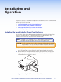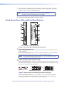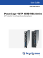
1
User Guide
PowerCage Products
PowerCage™ MTP 15HD RSA Series
MTP Twisted Pair Transmitter and Receiver Modular Boards
68-1644-01 Rev. A
08 10
Safety Instructions • English
Warning
This symbol is intended to alert the user of important operating and maintenance (servicing) instructions in the literature provided with the equipment.
Power sources • This equipment should be operated only from the power source indicated on the product. This
equipment is intended to be used with a main power system with a grounded (neutral) conductor. The third
(grounding) pin is a safety feature, do not attempt to bypass or disable it.
This symbol is intended to alert the user of the presence of uninsulated
dangerous voltage within the product’s enclosure that may present a risk of
electric shock.
Power disconnection • To remove power from the equipment safely, remove all power cords from the rear of
the equipment, or the desktop power module (if detachable), or from the power source receptacle (wall plug).
Caution
Read Instructions • Read and understand all safety and operating instructions before using the equipment.
Retain Instructions • The safety instructions should be kept for future reference.
Follow Warnings • Follow all warnings and instructions marked on the equipment or in the user information.
Avoid Attachments • Do not use tools or attachments that are not recommended by the equipment
manufacturer because they may be hazardous.
Consignes de Sécurité • Français
Ce symbole sert à avertir l’utilisateur que la documentation fournie avec le
matériel contient des instructions importantes concernant l’exploitation et la
maintenance (réparation).
Ce symbole sert à avertir l’utilisateur de la présence dans le boîtier
de l’appareil de  tensions dangereuses non isolées posant des risques
d’électrocution.
Attention
Lire les instructions• Prendre connaissance de toutes les consignes de sécurité et d’exploitation avant
d’utiliser le matériel.
Conserver les instructions• Ranger les consignes de sécurité afin de pouvoir les consulter à l’avenir.
Respecter les avertissements • Observer tous les avertissements et consignes marqués sur le matériel ou
présentés dans la documentation utilisateur.
Eviter les pièces de fixation • Ne pas utiliser de pièces de fixation ni d’outils non recommandés par le
fabricant du matériel car cela risquerait de poser certains dangers.
Sicherheitsanleitungen • Deutsch
Power cord protection • Power cords should be routed so that they are not likely to be stepped on or pinched
by items placed upon or against them.
Servicing • Refer all servicing to qualified service personnel. There are no user-serviceable parts inside. To prevent
the risk of shock, do not attempt to service this equipment yourself because opening or removing covers may
expose you to dangerous voltage or other hazards.
Slots and openings • If the equipment has slots or holes in the enclosure, these are provided to prevent
overheating of sensitive components inside. These openings must never be blocked by other objects.
Lithium battery • There is a danger of explosion if battery is incorrectly replaced. Replace it only with the
same or equivalent type recommended by the manufacturer. Dispose of used batteries according to the
manufacturer’s instructions.
Avertissement
Alimentations • Ne faire fonctionner ce matériel qu’avec la source d’alimentation indiquée sur l’appareil. Ce
matériel doit être utilisé avec une alimentation principale comportant un fil de terre (neutre). Le troisième
contact (de mise à la terre) constitue un dispositif de sécurité : n’essayez pas de la contourner ni de la
désactiver.
Déconnexion de l’alimentation• Pour mettre le matériel hors tension sans danger, déconnectez tous les
cordons d’alimentation de l’arrière de l’appareil ou du module d’alimentation de bureau (s’il est amovible) ou
encore de la prise secteur.
Protection du cordon d’alimentation • Acheminer les cordons d’alimentation de manière à ce que personne
ne risque de marcher dessus et à ce qu’ils ne soient pas écrasés ou pincés par des objets.
Réparation-maintenance • Faire exécuter toutes les interventions de réparation-maintenance par un
technicien qualifié. Aucun des éléments internes ne peut être réparé par l’utilisateur. Afin d’éviter tout danger
d’électrocution, l’utilisateur ne doit pas essayer de procéder lui-même à ces opérations car l’ouverture ou le
retrait des couvercles risquent de l’exposer à de hautes tensions et autres dangers.
Fentes et orifices • Si le boîtier de l’appareil comporte des fentes ou des orifices, ceux-ci servent à empêcher les
composants internes sensibles de surchauffer. Ces ouvertures ne doivent jamais être bloquées par des objets.
Lithium Batterie • Il a danger d’explosion s’ll y a remplacment incorrect de la batterie. Remplacer uniquement
avec une batterie du meme type ou d’un ype equivalent recommande par le constructeur. Mettre au reut les
batteries usagees conformement aux instructions du fabricant.
Vorsicht
Dieses Symbol soll dem Benutzer in der im Lieferumfang enthaltenen
Dokumentation besonders wichtige Hinweise zur Bedienung und Wartung
(Instandhaltung) geben.
Stromquellen • Dieses Gerät sollte nur über die auf dem Produkt angegebene Stromquelle betrieben werden.
Dieses Gerät wurde für eine Verwendung mit einer Hauptstromleitung mit einem geerdeten (neutralen) Leiter
konzipiert. Der dritte Kontakt ist für einen Erdanschluß, und stellt eine Sicherheitsfunktion dar. Diese sollte nicht
umgangen oder außer Betrieb gesetzt werden.
Dieses Symbol soll den Benutzer darauf aufmerksam machen, daß im Inneren
des Gehäuses dieses Produktes gefährliche Spannungen, die nicht isoliert sind
und die einen elektrischen Schock verursachen können, herrschen.
Stromunterbrechung • Um das Gerät auf sichere Weise vom Netz zu trennen, sollten Sie alle Netzkabel aus der
Rückseite des Gerätes, aus der externen Stomversorgung (falls dies möglich ist) oder aus der Wandsteckdose
ziehen.
Achtung
Lesen der Anleitungen • Bevor Sie das Gerät zum ersten Mal verwenden, sollten Sie alle Sicherheits-und
Bedienungsanleitungen genau durchlesen und verstehen.
Aufbewahren der Anleitungen • Die Hinweise zur elektrischen Sicherheit des Produktes sollten Sie
aufbewahren, damit Sie im Bedarfsfall darauf zurückgreifen können.
Befolgen der Warnhinweise • Befolgen Sie alle Warnhinweise und Anleitungen auf dem Gerät oder in der
Benutzerdokumentation.
Keine Zusatzgeräte • Verwenden Sie keine Werkzeuge oder Zusatzgeräte, die nicht ausdrücklich vom
Hersteller empfohlen wurden, da diese eine Gefahrenquelle darstellen können.
Instrucciones de seguridad • Español
Este símbolo se utiliza para advertir al usuario sobre instrucciones importantes de operación y mantenimiento (o cambio de partes) que se desean
destacar en el contenido de la documentación suministrada con los equipos.
Este símbolo se utiliza para advertir al usuario sobre la presencia de elementos con voltaje peligroso sin protección aislante, que puedan encontrarse
dentro de la caja o alojamiento del producto, y que puedan representar
riesgo de electrocución.
Precaucion
Leer las instrucciones • Leer y analizar todas las instrucciones de operación y seguridad, antes de usar el
equipo.
Conservar las instrucciones • Conservar las instrucciones de seguridad para futura consulta.
Obedecer las advertencias • Todas las advertencias e instrucciones marcadas en el equipo o en la
documentación del usuario, deben ser obedecidas.
安全须知 • 中文
这个符号提示用户该设备用户手册中有重要的操作和维护说明。
这个符号警告用户该设备机壳内有暴露的危险电压,有触电危险。
注意
阅读说明书 • 用户使用该设备前必须阅读并理解所有安全和使用说明。
保存说明书 • 用户应保存安全说明书以备将来使用。
遵守警告 • 用户应遵守产品和用户指南上的所有安全和操作说明。
避免追加 • 不要使用该产品厂商没有推荐的工具或追加设备,以避免危险。
Schutz des Netzkabels • Netzkabel sollten stets so verlegt werden, daß sie nicht im Weg liegen und niemand
darauf treten kann oder Objekte darauf- oder unmittelbar dagegengestellt werden können.
Wartung • Alle Wartungsmaßnahmen sollten nur von qualifiziertem Servicepersonal durchgeführt werden.
Die internen Komponenten des Gerätes sind wartungsfrei. Zur Vermeidung eines elektrischen Schocks
versuchen Sie in keinem Fall, dieses Gerät selbst öffnen, da beim Entfernen der Abdeckungen die Gefahr eines
elektrischen Schlags und/oder andere Gefahren bestehen.
Schlitze und Öffnungen • Wenn das Gerät Schlitze oder Löcher im Gehäuse aufweist, dienen diese zur
Vermeidung einer Überhitzung der empfindlichen Teile im Inneren. Diese Öffnungen dürfen niemals von
anderen Objekten blockiert werden.
Litium-Batterie • Explosionsgefahr, falls die Batterie nicht richtig ersetzt wird. Ersetzen Sie verbrauchte Batterien
nur durch den gleichen oder einen vergleichbaren Batterietyp, der auch vom Hersteller empfohlen wird.
Entsorgen Sie verbrauchte Batterien bitte gemäß den Herstelleranweisungen.
Evitar el uso de accesorios • No usar herramientas o accesorios que no sean especificamente recomendados
por el fabricante, ya que podrian implicar riesgos.
Advertencia
Alimentación eléctrica • Este equipo debe conectarse únicamente a la fuente/tipo de alimentación eléctrica
indicada en el mismo. La alimentación eléctrica de este equipo debe provenir de un sistema de distribución
general con conductor neutro a tierra. La tercera pata (puesta a tierra) es una medida de seguridad, no
puentearia ni eliminaria.
Desconexión de alimentación eléctrica • Para desconectar con seguridad la acometida de alimentación
eléctrica al equipo, desenchufar todos los cables de alimentación en el panel trasero del equipo, o desenchufar
el módulo de alimentación (si fuera independiente), o desenchufar el cable del receptáculo de la pared.
Protección del cables de alimentación • Los cables de alimentación eléctrica se deben instalar en lugares
donde no sean pisados ni apretados por objetos que se puedan apoyar sobre ellos.
Reparaciones/mantenimiento • Solicitar siempre los servicios técnicos de personal calificado. En el interior no
hay partes a las que el usuario deba acceder. Para evitar riesgo de electrocución, no intentar personalmente la
reparación/mantenimiento de este equipo, ya que al abrir o extraer las tapas puede quedar expuesto a voltajes
peligrosos u otros riesgos.
Ranuras y aberturas • Si el equipo posee ranuras o orificios en su caja/alojamiento, es para evitar el
sobrecalientamiento de componentes internos sensibles. Estas aberturas nunca se deben obstruir con otros
objetos.
Batería de litio • Existe riesgo de explosión si esta batería se coloca en la posición incorrecta. Cambiar esta
batería únicamente con el mismo tipo (o su equivalente) recomendado por el fabricante. Desachar las baterías
usadas siguiendo las instrucciones del fabricante.
警告
电源 • 该设备只能使用产品上标明的电源。 设备必须使用有地线的供电系统供电。 第三条线
(地线)是安全设施,不能不用或跳过 。
拔掉电源 • 为安全地从设备拔掉电源,请拔掉所有设备后或桌面电源的电源线,或任何接到市
电系统的电源线。
电源线保护 • 妥善布线, 避免被踩踏,或重物挤压。
维护 • 所有维修必须由认证的维修人员进行。 设备内部没有用户可以更换的零件。为避免出现
触电危险不要自己试图打开设备盖子维修该设备。
通风孔 • 有些设备机壳上有通风槽或孔,它们是用来防止机内敏感元件过热。 不要用任何东
西挡住通风孔。
锂电池 • 不正确的更换电池会有爆炸的危险。必须使用与厂家推荐的相同或相近型号的电池。
按照生产厂的建议处理废弃电池。
FCC Class A Notice
This equipment has been tested and found to comply with the limits for a Class A digital device, pursuant to part 15
of the FCC Rules. Operation is subject to the following two conditions:
1. This device may not cause harmful interference.
2. This device must accept any interference received, including interference that may cause undesired operation.
The Class A limits are designed to provide reasonable protection against harmful interference when the equipment
is operated in a commercial environment. This equipment generates, uses, and can radiate radio frequency energy
and, if not installed and used in accordance with the instruction guide, may cause harmful interference to radio
communications. Operation of this equipment in a residential area is likely to cause harmful interference, in which
case the user will be required to correct the interference at his own expense.
Symbol Convention
The following symbols are used throughout the guide and carry the following meanings:
TIP: A Tip provides a suggestion to make setting up or working with the device easier.
NOTE: A Note draws attention to important information.
CAUTION: A Caution warns of things or actions that might damage the equipment.
WARNING: A Warning warns of things or actions that might cause injury, death, or
other severe consequences.
Copyright
© 2010 Extron Electronics. All rights reserved.
Trademarks
All trademarks mentioned in this guide are the properties of their respective owners.
Contents
Introduction............................................. 1
Reference Information........................... 12
About this Guide.............................................. 1
About the PowerCage MTP 15HD RSA
Transmitters and Receivers............................... 1
Features............................................................ 2
Specifications.................................................. 12
Part Numbers.................................................. 15
PowerCage MTP 15HD RSA Part Numbers.. 15
Included Parts............................................. 15
Cables and Connectors............................... 15
Installation and Operation...................... 4
Installing the Boards into the PowerCage
Enclosure......................................................... 4
Board Connections, LEDs, and Rear Panel
Features........................................................... 5
PowerCage Front Panel Port, Control, and
Indicators......................................................... 8
Board Setup and Operation............................... 9
Changing the MTP T 15HD RSA Board
Settings....................................................... 9
Changing the MTP T 15HD RSA Board
Settings..................................................... 10
Skew, Level, and Peaking Adjustments........ 10
Operation................................................... 11
PowerCage MTP T 15HD RSA and PowerCage MTP R 15HD RSA SEQ • Contents
i
Introduction
• About this Guide
• About the PowerCage™ MTP 15HD RSA Transmitters and Receivers
• Features
About this Guide
This guide contains information about the following Extron®
PowerCageMTP 15HD RSA modular board-designed twisted pair transmitters and receivers
for the PowerCage Modular Power Enclosures:
• PowerCage MTP T 15HD RSA transmitter
• PowerCage MTP R 15HD RSA SEQ receiver
This guide includes instructions for an experienced installer to install, configure, and operate
the equipment.
NOTE: In this guide, the term “PowerCage MTP 15HD RSA” refers to both
MTP T 15HD RSA transmitter and MTP R 15HD RSA SEQ receiver boards.
Where differences exist between the two boards, the full name of the board is
used in the description.
About the PowerCage MTP 15HD RSA Transmitters and Receivers
The Extron PowerCage MTP 15HD RSA transmitters and receivers are modular boarddesigned MTP Twisted Pair boards that are exclusively for use in Extron PowerCage 1600
enclosure. They can be used with any CAT 5, 5e, or 6, or with Extron Enhanced Skew-Free™
A/V UTP cable, and are compatible with all MTP products.
The PowerCage MTP 15HD RSA transmitters and receivers must be installed in an Extron
PowerCage enclosure.
NOTE: To mount and install the Extron PowerCage, refer to the guide supplied with the
unit, or the PowerCage 1600 Enclosure User Guide, at www.extron.com.
The PowerCage MTP 15HD RSA transmitters and receivers boards are as follows:
• PowerCage MTP T 15HD RSA transmitter — This board supports RGB, HD-YUV, YUV,
S-video and composite video on a 15-pin HD VGA connector, and audio on a 5-pole
captive screw connector. The output to a compatible MTP receiver is made over twisted
pair cabling (CAT 5, 5e, 6, or Enhanced Skew-Free UTP cable) via the RJ-45 connector.
There is a 3-pole, captive screw connector for RS-232 communication.
A 2-pole DIP switch on the board allows the user (using switch #2) to select between
RS-232 and audio transmission (default setting is audio).
NOTE: See the “Board Setup and Operation” section, for details of how to access
and set the DIP switches.
PowerCage MTP T 15HD RSA and PowerCage MTP R 15HD RSA SEQ • Introduction
1
The transmitter board also features EDID emulation, whereby the correct refresh rate
and resolution is applied to the incoming computer signal, ensuring a proper image
output display.
Two DIP switches on the board allows the user to set the refresh rate to 50 or 60 Hz
(default is 60 Hz) using switch #1. The second switch controls the RS-232/audio setting.
The resolution is selected by turning the 16-position rotary encoder to the desired
setting. The default setting is 1024x768.
NOTE: The EDID encoder and DIP switch combination point to pre-stored EDID
information block to send to the RGB input. See the “Board Setup and
Operation” section for a table of settings, and details of how to access set
the switches and encoder.
In addition, a toggle switch on the rear panel is available to turn the pre-peaking on or
off. When turned on, pre-peaking boosts signal transmission distance.
The rear panel has an LED that lights green when power is applied to the board.
• PowerCage MTP R 15HD RSA SEQ receiver — This board supports RGB, HD-YUV,
YUV, S-video and composite video outputs on a 15-pin HD VGA connector, and audio or
RS-232 on a 5-pole captive screw connector.
The input from a compatible MTP transmitter is made over twisted pair cabling via the
RJ-45 connector.
This board has a level, peaking, and skew adjustment feature. When adjustment is
necessary, the selection between skew, level, and peaking is made via a recessed button.
The single digital encoder is used to adjust each individual setting (red skew, green skew,
blue skew, level and peaking) as needed.
Four DIP switches on the board allow the user to set the horizontal sync (switch #1),
vertical sync (switch #2), bi- or unidirectional RS-232 communication (switch #3), and
routing S-video (switch #4). Switches 5 and 6 are not used.
The rear panel also has an LED that lights green when power is applied to the board.
NOTE: For full operating details, see the “Installation and Operation” section, in
this guide.
Features
• Modular, field-upgradeable, and hot-swappable boards designed for the PowerCage
1600 enclosure — Additional transmitter and receiver boards may be added at any
time for quick and easy upgradeability or expansion. Hot-swappable components allow
the user to replace boards at any time with no need to power down the system. This is
useful for mission-critical applications that require continuous system operation.
• Space-saving design in a compact 3U, rack-mountable enclosure — The compact design
of the PowerCage 1600 enclosure accommodates up to 16 single-slot or 8 double-slot
boards. The PowerCage 1600 eliminates individual power supplies for each transmitter
and receiver, and provides forced-air cooling for each module.
• Supports RGBHV, RGBS, RGsB, RsGsBs, component video, composite video, and S-video
• Compatible with HDTV component video, bi-level or tri-level sync
• LED power indicator
• Compatible with all MTP products
PowerCage MTP T 15HD RSA and PowerCage MTP R 15HD RSA SEQ • Introduction
2
• PowerCage MTP T 15HD RSA transmits high resolution video and mono audio or
RS-232 signals 600 feet (185 meters) or more over a single twisted pair cable.
оо Inputs: Female 15-pin HD connector for video, 5-pole captive screw connector for
audio input, 3-pole captive screw connector for RS-232 communication.
оо Output: Female RJ-45 connector
оо EDID emulation — A selectable feature for specifying the rate of the incoming
VGA signal, EDID emulation allows proper communication with the video source.
оо Switchable video output pre-peaking — Provides additional compensation for
optimal performance on the longest cable runs, ensuring the highest quality signal
at the display.
PowerCage MTP R 15HD RSA SEQ receives high resolution video and mono audio or
RS-232 signals 600 feet (185 meters) or more over a single twisted pair cable
оо Input: Female RJ-45 connector
оо Outputs: Female 15-pin HD connector for video, 5-pole captive screw connector
for audio or RS-232 communication.
оо Compatible with HDTV component video, bi-level or tri-level sync
оо Separate variable level and peaking controls
оо Independent skew compensation adjustments for each color
PowerCage MTP T 15HD RSA and PowerCage MTP R 15HD RSA SEQ • Introduction
3
Installation and
Operation
This section describes the installation and operation of the PowerCage MTP T 15HD RSA and
MTP R 15HD RSA SEQ, including:
• Installing the Boards into the PowerCage Enclosure
• Board Connections, LEDs, and Rear Panel Features
• PowerCage Front Panel Port, Control, and Indicators
• Board Setup and Operation
Installing the Boards into the PowerCage Enclosure
Up to 16 single slot or 8 dual slot input/output boards can be inserted into the PowerCage
enclosure. The PowerCage MTP T 15HD RSA transmitters are single slot boards, and
PowerCage MTP R 15HD RSA SEQ receivers are dual slot boards.
NOTES: The boards are hot-swappable; they can be installed or removed without
turning off or disconnecting the power to the PowerCage enclosure.
CAUTION: Use ESD precautions when installing a board to avoid damaging the board.
Keep the board in the anti-static bag until needed. Use proper grounding
techniques during installation..
1. Where applicable, remove as many blank plates or previously installed boards from the
rear of the PowerCage as necessary for the number of new boards to be installed.
2. Hold the board with the signal connectors towards you and the LED at the top, and
align the top and bottom grooves of the board with the slide posts in the selected
enclosure slot. See the example in figure 1.
16 Available Single Board Slots or
8 Double Board Slots
age
erC AV
Pow R
MTP
Power
Supply
INPUT
age I
-SD
erC
Pow HD
3G
C
Tx
Rx
FOX
Y/VID
2
1
MONO
AUDIO OUTPUT
MODE
HD/SDI INPUT
SHARP GAIN
Rx
Tx
1 2
Tx Rx
REMOTE
RS-232 ALARM
Tx Rx
RS-232
OVER FIBER
AUDIO
L
R
Align board and
slide into slot.
RGB
OUTPUT
HD/SDI OUTPUTS
age B
RG
erC
Pow RX
4G
FOX
age B
RG
erC
Pow RX
4G
Tx Rx
Tx
REMOTE
RS-232 ALARM
RS-232
OVER FIBER
AUDIO
L
R
RGB
Screws
(2 per board)
Tx Rx
TED
LIS 3
1T2
E.
I.T.
0Hz
OUTPUT
778
1 2
Rx
FOX
US
C
N15
50/6
V X.
-240 MA
100 5A
Figure 1. Inserting Boards into the PowerCage Enclosure
PowerCage MTP T 15HD RSA and PowerCage MTP R 15HD RSA SEQ • Installation and Operation
4
3. Carefully slide the board into the slot, aligning the two tabs on the lower front end of
the board with the matching ports in the enclosure. Push the board firmly into place.
Tighten the screws to secure the board in place.
NOTE: Use a tool to fully tighten the screws after initial installation and
subsequent removal and replacement of the boards..
4. Repeat steps 2 and 3 for all boards needing installation.
Board Connections, LEDs, and Rear Panel Features
4
OUTPUT
INPUT
3
OUTPUT
OFF
PRE-PEAK
ON
3
5
PowerCage
MTP R
15HD RSA SEQ
PowerCage
MTP T
15HD RSA
4
PowerCage
MTP T 15HD RSA
Tx Rx
2
ADJUST
R
9
SELECT
L
8
R
G/L
B/P
Tx Rx
6
RS-232
2
AUDIO INPUT
1
AUDIO RS-232
INPUT
1
7
PowerCage
MTP R 15HD RSA SEQ
Figure 2. PowerCage MTP 15HD RSA Board Connectors
a 15-pin HD VGA connectors —
MTP T 15HD RSA board — Connect RGB, HD-YUV, YUV, S-video, or composite inputs
to this connector.
MTP R 15HD RSA SEQ board — Connect suitable display devices to this connector for
RGBHV, RGBS, RGsB, RsGsBs, HD-YUV, YUV, S-video, or composite output.
NOTE: DIP switch settings on the receiver allows the user to switch chroma from
the red channel to the blue channel.
b Audio connector (5-pole captive screw) —
MTP T 15HD RSA board — Connect an audio input source to the 5-pole captive screw
connector. Wire the captive screw connector as shown below. Use the supplied tie-wrap
to secure the audio cable to the connector.
Tip
Sleeve
Unbalanced Stereo Input
R
Do not tin the wires!
Tip
Ring
Sleeve (s)
Tip
Ring
L
Tip
Sleeve
Balanced Stereo Input
Figure 3. Captive Screw Connector Wiring for Stereo Audio Input
MTP R 15HD RSA SEQ board — On this board, this is an audio and RS-232 output
connector. Wire and insert a 5-pole captive screw connector for mono audio and/or
RS-232 serial output. Wire the connector as shown in figure 4.
PowerCage MTP T 15HD RSA and PowerCage MTP R 15HD RSA SEQ • Installation and Operation
5
NOTE: The receiver auto-detects whether the signal on the audio/RS-232 pair of the
TP input is audio or RS-232. It then converts the signal content accordingly,
and outputs the signals on the appropriate pins of this connector.
Tx Rx
Tx Rx
RS-232
Device
Do not tin the wires!
Tip
Ring
Sleeve
Mono Audio Output
Ground ( )
Transmit (Tx)
Receive (Rx)
Bidirectional
Ground ( )
Transmit (Tx)
Receive (Rx)
RS-232 Output
Figure 4. Captive Screw Connector Wiring for Audio and/or RS-232 Output
NOTE: The length of exposed wires is critical. The ideal length is 3/16 inch (5 mm).
If the stripped section of wire is longer than 3/16 inch, the exposed wires may
touch, causing a short circuit. If it is shorter than 3/16 inch, wires can be easily
pulled out of the captive screw connectors.
Figure 5 identifies the tip, ring, and sleeve parts of standard audio connectors. A mono
(RCA) audio connector consists of the tip and sleeve. A stereo audio connector consists of
the tip, ring and sleeve. The tip, ring, and sleeve wires are also shown on the captive screw
audio connector diagrams.
Tip (+)
Sleeve ( )
RCA Connector
Tip (+)
Ring (-)
Sleeve ( )
3.5 mm Stereo Plug Connector
(balanced)
Figure 5. Typical Audio Connectors
c RJ-45 connector —
MTP T 15HD RSA board — Connect the transmitter
to a suitable MTP receiver via this connector. Terminate
the cable as shown at right, using the same standard
(A or B) at both ends
MTP R 15HD RSA SEQ board — Connect the twisted
pair cable from the transmitter to this input connector.
Terminate the cable using the same standard (A or B)
at both ends.
RJ-45
Connector
Pins:
12345678
T568A
Wire color
Pin
T568B
Wire color
1
White-green
White-orange
2
Green
Orange
3
White-orange White-green
4
Blue
5
White-blue
White-blue
6
Orange
Green
Blue
7
White-brown
White-brown
8
Brown
Brown
Insert Twisted
Pair Wires
NOTE: If using Enhanced Skew-Free A/V cable, use the TIA T568A standard only.
CAUTION: Do not connect the twisted pair input cables to any devices LAN port, or
connect a LAN cable to the MTP ports.
d Power LED — This LED lights green to indicate that power is applied to the board.
e Pre-peaking toggle switch (MTP T 15HD RSA only) — This switch toggles pre-peaking
on or off. Pre-peaking boosts the transmission distance for long cable runs.
NOTE: The transmission distance varies greatly depending on the signal resolution
and on the type of cable, graphic card, and display used in the system.
See distance table on page 7
PowerCage MTP T 15HD RSA and PowerCage MTP R 15HD RSA SEQ • Installation and Operation
6
Maximum Transmitter to Receiver Distance — Analog Signals at 60 Hz
Video Format
With Pre-Peak Off. With Pre-Peak On.
Feet (Meters)
Feet (Meters)
Composite,
S-video,
Component Video
Max. Distance
(High Quality).
Feet (Meters)
Max. Distance
(Variable Quality).
Feet (Meters)
800 (245)
1000 (300)
640 x 480
<300 (90)
>350 (105)
700 (215)
750 (230)
800 x 600
<300 (90)
>350 (105)
550 (170)
650 (200)
1024 x 768*
<300 (90)
>350 (105)
500 (150)
600 (185)
1280 x 960
<300 (90)
>350 (105)
400 (120)
500 (150)
1280 x 1024*
<250 (75)
>300 (90)
350 (105)
450 (135)
1360 x 765
<250 (75)
>300 (90)
400 (120)
500 (150)
1365 x 768
<250 (75)
>300 (90)
400 (120)
450 (135)
1366 x 768
<250 (75)
>300 (90)
400 (120)
450 (135)
1400 x 1050
<250 (75)
>300 (90)
350 (105)
400 (120)
1440 x 900
<250 (75)
>300 (90)
350 (105)
400 (120)
1600 x 1200*
<250 (75)
>300 (90)
300 (90)
450 (135)
1920 x 1200
<250 (75)
>300 (90)
300 (90)
400 (120)
2048 x 1080
<250 (75)
>300 (90)
300 (90)
400 (120)
HDTV 720p
<250 (75)
>300 (90)
400 (120)
500 (150)
HDTV 1080i
<250 (75)
>300 (90)
300 (90)
400 (120)
HDTV 1080p
<250 (75)
>300 (90)
300 (90)
400 (120)
* same spec at 75 Hz
Figure 6. Maximum Transmission Distances for Analog Signals at 60 Hz
f RS-232 connector (3-pole captive screw - MTP T 15HD RSA only) — Connect to this for
bi- or unidirectional RS-232 communication. The RS-232 function is only available by setting
the on-the-board DIP switch from audio to RS-232 communication. The default is audio.
See page 8 for setting the DIP switch.
g Skew, Peaking and Level LEDs (MTP R 15HD RSA SEQ only) — These three LEDs
(red, green, and blue) are used to indicate the misaligned colors when adjusting the Skew
Equalization settings. They are also used for identifying Peaking and Level modes when
adjusting for signal loss or optimizing the image for various cable lengths. The LEDs are
labelled: R =Red, G/L = Green/Level, B/P = Blue/Peaking
NOTES: Skew is the color misalignment present in twisted pair A/V systems using
Category 5, 5e, or 6 cable in which the red, green, and blue video signals
arrive at the display at different times.
Level alters the video output voltage to affect the brightness of the
displayed image.
Peaking affects the sharpness of a picture.
h Select Button (MTP R 15HD RSA SEQ only) — This recessed button selects between,
Skew Equalization, Level, and Peaking when adjustments are needed.
i Rotary Adjust Knob
(MTP R 15HD RSA SEQ only) — Within any function, rotate this
Adjust knob to make the appropriate changes to the skew delay, level, or peaking.
PowerCage MTP T 15HD RSA and PowerCage MTP R 15HD RSA SEQ • Installation and Operation
7
PowerCage Front Panel Port, Control, and Indicators
The following features are on the front panel of the PowerCage enclosure.
1
2
3
14
15
16
COMM
POWER
ALARM
PSU
1
PSU
2
FAN
1
FAN
2
COMM
SELECT
TEMP
CONFIG
PowerCage 1600
1 2 3
4
5
6
Figure 7. PowerCage Front Panel
a Comm LED (Slots 1-16) — This LED lights to indicate that the board at this location is
selected for connection to the Configuration port (item e). Repeatedly press the Comm
Select button (item d) to select the desired slot and installed board.
NOTE: The Comm function only works with fiber optic boards.
b Power LED (Slots 1-16, PSUs 1 and 2, Fans 1 and 2) — This LED lights to indicate that
power is applied to the board at any of the slots.
c Alarm LED (Slots 1-16, PSUs 1 and 2, Fans 1 and 2) — For use with fiber optic boards,
where installed. This LED lights to indicate that light is received on any installed fiber optic
board Rx connector at this location.
d Comm Select button — Repeatedly press this button to select the desired board for
connection to the Configuration port. The Comm LED (item a) for the selected board lights.
See Note above.
e Configuration port — This 2.5 mm mini stereo jack communicates with a connected PC
to enable bi- or unidirectional RS-232 with the installed fiber optic boards. Use the optional
Extron 9-pin D to 2.5 mm mini jack TRS RS‑232 cable, part #70-335-01, for this connection.
NOTE: The Comm port function only works fiber optic boards.
6 feet
(1.8 m)
1
5
6
Part #70-335-01
9
Tip
Ring
Sleeve (Gnd)
9-pin D
Pin 2
Pin 3
Pin 5
Connection
TRS Plug
Computer's RX line
Tip
Computer's TX line
Ring
Computer's signal ground Sleeve
Figure 8. 9-pin TRS RS-232 Cable 70-335-01
This port is RS-232 only, with the following protocols:
9600 baud, no parity, 8 data bits, 1 stop bit, no flow control
f Temperature LED — This LED lights if the temperature within the PowerCage enclosure is
high (approximately 167 °F [75 °C]) and equipment damage is imminent.
PowerCage MTP T 15HD RSA and PowerCage MTP R 15HD RSA SEQ • Installation and Operation
8
Board Setup and Operation
On the MTP T 15HD RSA board there are two DIP switches (switch #1 is for refresh rate,
switch #2 is for audio/RS-232), and a 16-position rotary encoder for EDID selection.
The factory set defaults for these are:
• DIP switch #1 is 60 Hz (down)
• DIP switch #2 is audio (down)
• EDID encoder is 1024x768 (position 2)
On the MTP R 15HD RSA SEQ board there are four active DIP switches. These are:
switch #1 = Horizontal sync, switch #2 = Vertical sync, switch 3 = RS-232 communication,
switch #4 = S-video chroma routing, switch #5 = not used, switch #6 = not used.
The factory default settings for these are:
• DIP switch #1 is H– (down)
• DIP switch #2 is V– (down)
• DIP switch #3 is unidirectional RS-232 (down)
• DIP switch #4 is MTP compatible (down)
• DIP switch #5 and #6 not used (down)
For both boards, access to the DIP switches and encoder is via a cut-out in the cover. If the
settings need to be changed from the default setting, they should be set before the board
is installed.
Alternatively, if changes are to be made after a board is installed, the board should be
removed from the PowerCage by loosening the top and bottom retaining screws and
carefully pulling the board out of its slot.
Changing the MTP T 15HD RSA Board Settings
1. Set the DIP switches as required.
Switch Position
Switch #1 Setting
Switch #2 Setting
Up/On
50 Hz
RS-232
Down/Off (default)
60 Hz
Audio
O 1
N
2
a. Select RS-232 setting where RS-232 communication is desired.
b. Select the desired refresh rate.
2. Using a small screwdriver, rotate the encoder pointer to the number or letter
corresponding to the resolution required.
See below for EDID encoder positions and resolutions:
Position
Resolution
Position
Resolution
0
N/A
8
1366 x 768
1
800 x 600
9
1400 x 1050
2
1024 x 768 (default)
A
1440 x 900
3
1280 x720
B
1600 x 1200
4
1280 x 768
C
1680 x 1050
5
1280 x 800
D
1920 x 1080
6
1280 x 1024
E
1920 x 1200
7
1360 x 768
F
N/A
PowerCage MTP T 15HD RSA and PowerCage MTP R 15HD RSA SEQ • Installation and Operation
9
Changing the MTP T 15HD RSA Board Settings
Change any of the four active DIP switches to the settings as shown in the table below.
Switch
Position
Switch #1 Switch #2 Switch #3
Setting
Setting
Setting
Switch #4
Setting
Switch #5 Switch #6
Setting
Setting
Up/On
H+
S-Video
green = luma
blue = chroma
N/A
MTP standard
green = luma
red = chroma
N/A
Down/Off H(default)
V+
Bidirectional
V-
Unidirectional
N/A
N/A
ON
1 2 3 4 5 6
1 = H SYNC
2 = V SYNC
3 = RS-232
4 = S-Video/MTP
5 = Not Used
6 = Not Used
1. To change either horizontal or vertical sync to positive, flip DIP switches 1 or 2
to up/on.
2. To change the RS-232 from unidirectional to bidirectional, flip DIP switch 3 to up/on.
3. To change signal routing for S-video signals, flip DIP switch 4 to up/on.
NOTE: The fourth DIP switch is used for S-video routing of the chroma signal to the
blue channel. When the switch is up (on) position (green = luma,
blue = chroma), S-video is compatible with the Extron Signal Processing
Products line, (for example DVS 304).
When the switch is down (off), the signal follows the MTP standard and is
output on the green and red channels of the VGA.
Switches 5 and 6 are not used.
Skew, Level, and Peaking Adjustments
See the Note on page 7 about skew delay, level, and peaking.
On the rear panel of the MTP R 15HD RSA SEQ board are three colored LEDs, a recessed
select button, and an Adjust knob. These work in conjunction to allow the user to make
adjustments to image skew delay, level, and peaking.
The select button allows the user to select any of the three individual functions for
adjustment. When the select button is pressed a set number of times, the LED’s indicate
the current function. Press the select button as follows:
Button
presses
Function
LED Color
1
Red skew delay
Red
2
Green skew delay
Green
3
Blue skew delay
Blue
4
Level
Green (Blinking)
5
Peaking
Blue (Blinking)
For Skew adjustment.
1. View the image critically, and note the color that is shifted furthest right.
NOTE: This color cannot be adjusted leftward, but the remaining two colors can
be adjusted from left to right until all three colors converge.
PowerCage MTP T 15HD RSA and PowerCage MTP R 15HD RSA SEQ • Installation and Operation
10
2. Noting the color that is shifted furthest left, press the select button accordingly to
select that color (see table above). The corresponding LED lights.
3. Viewing the image, slowly rotate the Adjust knob until the selected color converges
with the color furthest right.
4. Repeat steps 2 and 3 for the remaining color until all three colors are converged.
For Level Adjustment.
1. Press the select button four times to enter the level function. The green LED blinks.
2. View the image critically and rotate the adjust knob to increase or decrease the
brightness of the displayed image.
For Peaking Adjustment.
1. Press the select button five times to enter the level function. The blue LED blinks.
2. View the image critically and rotate the adjust knob to increase or decrease the
sharpness of the displayed image.
Resetting Skew Delay, Level and Peaking
To reset the skew delay, level, and peaking, press and hold the select button for three
seconds. Release the select button.
Operation
After the transmitter, all receivers, and their connected devices are powered up, the system
is fully operational. To optimize the displayed image make any appropriate adjustments as
described in this guide.
If any problems are encountered, verify that the cables are routed and connected properly,
and that all display devices have suitable resolutions and refresh rates, and the image has
been optimized as far as possible.
If your problems persist, call the Extron S3 Sales & Technical Support Hotline. See the
contact numbers on the rear page of this guide for the Extron office nearest you.
PowerCage MTP T 15HD RSA and PowerCage MTP R 15HD RSA SEQ • Installation and Operation
11
Reference
Information
This section provides the specifications and part numbers for the
PowerCage MTP T 15HD RSA and MTP R 15HD RSA SEQ modular boards.
• Specifications
• Part Numbers
Specifications
Video — PowerCage MTP T 15HD RSA, PowerCage MTP R 15HD RSA SEQ
Gain����������������������������������������������� Unity
Number/signal type������������������������ 1 set of proprietary analog signals
Connector�������������������������������������� 1 female RJ-45
Video input — PowerCage MTP T 15HD RSA
Number/signal type������������������������ 1 analog RGBHV, RGBS, RGsB, RsGsBs, component video (YUVi or YUVp/HDTV),
S-video, or composite video
Connector�������������������������������������� 1 female 15-pin HD
Nominal levels�������������������������������� 1 Vp-p for Y of component video and S-video, and for composite video
0.7 Vp-p for RGB and for R-Y and B-Y of component video
0.3 Vp-p for C of S-video
Minimum/maximum levels�������������� 0.3 V to 1.45 Vp-p
Impedance������������������������������������� 75 ohms
Horizontal frequency���������������������� 15 kHz to 130 kHz
Vertical frequency��������������������������� 30 Hz to 150 Hz
Return loss������������������������������������� <-30 dB @ 5 MHz
DC offset (max. allowable)������������� 250 mV
Video output — PowerCage MTP R 15HD RSA SEQ
Number/signal type������������������������ 1 analog VGA-UXGA RGBHV, RGBS, RGsB, RsGsBs,
component video (YUVi or YUVp/HDTV), S-video, or composite video
Connector�������������������������������������� 1 female 15-pin HD
Nominal levels�������������������������������� 1 Vp-p for Y of component video and S-video, and for composite video
0.7 Vp-p for RGB and for R-Y and B-Y of component video
0.3 Vp-p for C of S-video
Minimum/maximum levels�������������� 0.3 V to 1.45 Vp-p
Impedance������������������������������������� 75 ohms
Return loss������������������������������������� <-30 dB @ 5 MHz
DC offset��������������������������������������� <±25 mV with input at 0 offset
Skew compensation����������������������� 62 ns
Maximum resolution���������������������� Up to 1920x1200 or 2048x1080 or 1080p at 300 ft
Up to 1024x768 at 600 ft
NOTE: Refer to page 7 in this guide for maximum distances recommended for specific resolutions.
PowerCage MTP T 15HD RSA and PowerCage MTP R 15HD RSA SEQ • Reference Information
12
Sync — PowerCage MTP T 15HD RSA, PowerCage MTP R 15HD RSA SEQ
Input/output type��������������������������� RGBHV, RGBS, RGsB, RsGsBs
Standards��������������������������������������� NTSC 3.58, NTSC 4.43, PAL, SECAM
Input level (transmitter)������������������ 3.5 V to 5.5 Vp-p, unterminated
Output level (receiver)�������������������� 4.0 V to 5.0 Vp-p, unterminated
Input impedance (transmitter)�������� 573 ohms ±5%
Output impedance (receiver)���������� 110 ohms
Polarity
Transmitter������������������������������ Positive or negative (follows input polarity)
Receiver����������������������������������� Positive or negative (switch-selectable)
Audio — PowerCage MTP T 15HD RSA, PowerCage MTP R 15HD RSA SEQ
Number/signal type������������������������ 1 set of proprietary analog signals
Connector�������������������������������������� 1 female RJ-45
Gain����������������������������������������������� Unbalanced output: 0 dB; balanced output: +6 dB
Frequency response������������������������ 20 Hz to 20 kHz, ±1 dB
THD + Noise����������������������������������� 0.15% @ 1 kHz, 0.3% @ 20 kHz at nominal level
S/N������������������������������������������������� >70 dB at maximum output (unweighted)
Stereo channel separation�������������� >60 dB @ 1 kHz
CMRR�������������������������������������������� >43 dB @ 20 Hz to 20 kHz
Audio input — PowerCage MTP T 15HD RSA
Number/signal type������������������������ 1 stereo, unbalanced
Connector�������������������������������������� (1) 3.5 mm captive screw connector, 5 pole
Impedance������������������������������������� >10k ohms, unbalanced
Nominal levels�������������������������������� +4 dBu (1.23 Vrms), -10 dBV (316 mVrms)
Maximum level������������������������������� +18 dBu, (unbalanced) at 1% THD+N
NOTE: 0 dBu = 0.775 Vrms, 0 dBV = 1 Vrms, 0 dBV ≈ 2 dBu
Audio output — PowerCage MTP R 15HD RSA SEQ
Number/signal type������������������������ 1 mono, balanced/unbalanced
Connector�������������������������������������� (1) 3.5 mm captive screw connector, 5 pole
Impedance������������������������������������� 50 ohms unbalanced, 100 ohms balanced
Gain error�������������������������������������� ±1 dB channel to channel
Nominal levels�������������������������������� +4 dBu (1.23 Vrms), -10 dBV (316 mVrms)
Maximum level������������������������������� +18 dBu, unbalanced at 1% THD+N
Control/Remote
Serial ports
Boards������������������������������������� Pass-through, uni- or bidirectional Input/output: 1 set of proprietary signals on female
RJ-45 jack
Output/input: 1 RS-232 via 3 poles of a 3.5 mm captive screw connector (3 pole for
transmitter, 5 pole for receiver)
Baud rate and protocol
Boards
Baud rates������������������������� Up to 38400 bps at up to 600 ft (185 m). Higher data rates and distances are possible. Performance varies based on baud rate and cable length.)
Protocol����������������������������� Data bits = 5 - 8
Stop bits = 1 or 2
Parity = odd, even, none
Flow control = XON, XOFF, none
Defaults: 8 data bits, 1 stop bit, no parity
NOTE: For PowerCage MTP boards, protocol is mirrored between the transmitter and the receiver.
Serial control pin configurations
Captive screw connector
Boards������������������������������� Transmitter: 1 = Tx, 2 = Rx, 3 = GND
Receiver: 3 = GND, 4 = Tx, 5 = Rx
Mini stereo jack����������������������� RS-232: tip = Tx, ring = Rx, sleeve = GND
PowerCage MTP T 15HD RSA and PowerCage MTP R 15HD RSA SEQ • Reference Information
13
General
Recommended cable type�������������� Extron Enhanced Skew-Free™ A/V UTP, CAT 5/5e/6 (shielded or unshielded)
Power consumption*��������������������� 1 or 2* (positive-negative), 100 VAC to 240 VAC, 50-60 Hz; internal, hot-swappable
*
A redundant power supply is optional.
Each MTP board at 115 VAC, 60 Hz
MTP T 15HD RSA: 4.30 watts
MTP R 15HD RSA SEQ: 8.38 watts
Power input requirements (I/O boards)
12 VDC, 1.0 A, supplied by the PowerCage enclosure
Temperature/humidity�������������������� Storage: -40 to +158 °F (-40 to +70 °C) / 10% to 90%, noncondensing
Operating: +32 to +122 °F (0 to +50 °C) / 10% to 90%, noncondensing
Cooling������������������������������������������ Boards: convection, within the PowerCage enclosure
Enclosure type�������������������������������� Metal
Enclosure dimensions
PowerCage MTP R 15HD RSA SEQ
Fits a double slot opening in a PowerCage enclosure.
PowerCage MTP T 15HD RSA � Fits a single slot opening in a PowerCage enclosure.
Product weight
PowerCage MTP R 15HD RSA SEQ
1.0 lbs (0.5 kg)
PowerCage MTP T 15HD RSA�� 0.8 lbs (0.4 kg)
Shipping weight
PowerCage boards������������������� 2 lbs (1 kg) each
Vibration���������������������������������������� ISTA 1A in carton (International Safe Transit Association)
Regulatory compliance
Safety�������������������������������������� CE, c-UL, UL
EMI/EMC��������������������������������� CE, C-tick, FCC Class A, ICES, VCCI
MTBF��������������������������������������������� 30,000 hours
Warranty���������������������������������������� 3 years parts and labor
NOTES: All nominal levels are at ±10%.
Specifications are subject to change without notice.
PowerCage MTP T 15HD RSA and PowerCage MTP R 15HD RSA SEQ • Reference Information
14
Part Numbers
PowerCage MTP 15HD RSA Part Numbers
The PowerCage MTP 15HD RSA boards must be installed in a PowerCage 1600 enclosure.
PowerCage Boards
Part number
PowerCage MTP T 15HD RSA
70-817-01
PowerCage MTP R 15HD RSA SEQ
70-818-01
Included Parts
These items are included in each order for a PowerCage MTP T 15HD RSA and
MTP R 15HD RSA SEQ:
Included parts
Part number
IEC power cord
Tweeker (small screwdriver)
Setup guide
Captive screw 3-pole connectors
100-456-01
Captive screw 5-pole connectors
100-457-01
Cables and Connectors
Accessory
Part number
Enhanced Skew Free A/V UTP cable
26-569-0x
Enhanced Skew-Free A/V cable, 1000 ft
(300m), non-plenum
22-141-03
Skew-Free UTP-P series, A/V cable,
75 ft (23 m)
26-570-07
CAT 6 Jack, black, Qty. 10
100-476-01
CAT 6 Jack, red, Qty. 10
100-477-01
CAT 6 Jack, blue, Qty. 10
100-478-01
CAT 6 Jack, orange, Qty. 10
100-479-01
CAT 6 Jack, gray, Qty. 10)
100-480-01
CAT 6 Jack, white, Qty. 10
100-481-01
CAT 6 Jack, ivory, Qty. 10
100-482-01
™
PowerCage MTP T 15HD RSA and PowerCage MTP R 15HD RSA SEQ • Reference Information
15
Extron® Warranty
Extron Electronics warrants this product against defects in materials and workmanship for a period of three years
from the date of purchase. In the event of malfunction during the warranty period attributable directly to faulty
workmanship and/or materials, Extron Electronics will, at its option, repair or replace said products or components,
to whatever extent it shall deem necessary to restore said product to proper operating condition, provided that it is
returned within the warranty period, with proof of purchase and description of malfunction to:
USA, Canada, South America,
and Central America:
Extron Electronics
1001 East Ball Road
Anaheim, CA 92805
U.S.A.
Japan:
Extron Electronics, Japan
Kyodo Building, 16 Ichibancho
Chiyoda-ku, Tokyo 102-0082
Japan
Europe, Africa, and the Middle
East:
Extron Europe
Hanzeboulevard 10
3825 PH Amersfoort
The Netherlands
China:
Extron China
686 Ronghua Road
Songjiang District
Shanghai 201611
China
Asia:
Extron Asia
135 Joo Seng Road, #04-01
PM Industrial Bldg.
Singapore 368363
Singapore
Middle East:
Extron Middle East
Dubai Airport Free Zone
F12, PO Box 293666
United Arab Emirates, Dubai
This Limited Warranty does not apply if the fault has been caused by misuse, improper handling care, electrical
or mechanical abuse, abnormal operating conditions, or modifications were made to the product that were not
authorized by Extron.
NOTE: If a product is defective, please call Extron and ask for an Application Engineer to receive an RA (Return
Authorization) number. This will begin the repair process.
USA: (714) 491-1500
Asia: +65.6383.4400
Europe:
Japan:
+31.33.453.4040
+81.3.3511.7655
Units must be returned insured, with shipping charges prepaid. If not insured, you assume the risk of loss or damage
during shipment. Returned units must include the serial number and a description of the problem, as well as the
name of the person to contact in case there are any questions.
Extron Electronics makes no further warranties either expressed or implied with respect to the product and its quality,
performance, merchantability, or fitness for any particular use. In no event will Extron Electronics be liable for direct,
indirect, or consequential damages resulting from any defect in this product even if Extron Electronics has been
advised of such damage.
Please note that laws vary from state to state and country to country, and that some provisions of this warranty may
not apply to you.
Extron USA - West
Headquarters
Extron USA - East
Extron Europe
Extron Asia
Extron Japan
Extron China
Extron Middle East
+800.633.9876
+800.633.9876
+800.3987.6673
+800.7339.8766
Inside Asia Only
+81.3.3511.7655
+81.3.3511.7656 FAX
+400.883.1568
Inside Europe Only
+971.4.2991800
+971.4.2991880 FAX
+1.919.863.1794
+1.919.863.1797 FAX
+31.33.453.4040
+31.33.453.4050 FAX
+65.6383.4400
+65.6383.4664 FAX
Inside USA/Canada Only
+1.714.491.1500
+1.714.491.1517 FAX
Inside USA/Canada Only
© 2010 Extron Electronics All rights reserved.
Inside China Only
+86.21.3760.1568
+86.21.3760.1566 FAX
www.extron.com