1
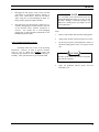
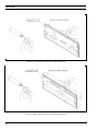
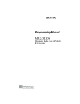
LBI-39175A SERVICE SECTION ORION™ 136-174 MHz Dual Bandwidth SYNTHESIZED TWO-WAY FM RADIO TABLE OF CONTENTS Page DESCRIPTION ........................................................................................................................... 2 INITIAL MEASUREMENTS ..................................................................................................... 2 TRANSMITTER ........................................................................................................... 2 RECEIVER.................................................................................................................... 2 MAINTENANCE ........................................................................................................................ 3 PREVENTIVE MAINTENANCE ................................................................................ 3 DISASSEMBLY PROCEDURE ................................................................................... 4 ALIGNMENT PROCEDURES ................................................................................................... 7 INTRODUCTION ......................................................................................................... 7 TRACKING DATA....................................................................................................... 9 TEST FREQUENCIES.................................................................................................. 9 SETTING TRACKING DATA .....................................................................................10 TRANSMITTER ALIGNMENT.................................................................................................11 PA TRANSISTOR REPLACEMENT...........................................................................11 RECEIVER ALIGNMENT .........................................................................................................12 TEST EQUIPMENT REQUIRED ................................................................................12 ADJUSTMENT PROCEDURES ..................................................................................12 SQUELCH ADJUSTMENT..........................................................................................13 TROUBLESHOOTING GUIDE .................................................................................................13 INTRODUCTION .........................................................................................................13 MICROPHONICS .........................................................................................................13 SERVICEABLE PARTS...............................................................................................14 DIAGNOSTIC PROCEDURES ..................................................................................................15 ADDITIONAL TOOLS REQUIRED............................................................................16 ERROR CODES............................................................................................................19 ericssonz LBI-39175A DESCRIPTION INITIAL MEASUREMENTS This section contains the information required to service the ORION VHF Dual Bandwidth two-way FM radio. Included are disassembly procedures, alignment procedures, and troubleshooting information (see Table of Contents). After the radio has been installed as described in the Installation Manual, the following measurements should be made by a certified electronics technician, and recorded for future reference: This radio is adjusted by setting personality parameters stored in the radio's computer memory. Therefore, all radio alignment procedures require the use of a Personal Computer (IBM PC or equivalent), along with a Programming Interface TQ3370, and an ORION PC Programming Cable TQ3377. PC Programming Software Version 4.00 or later is also required. This radio is designed to be serviced by replacement of modules and/or circuit boards. As such, there are very few serviceable component parts contained on any of the circuit boards within the radio. Normally, defective boards should be replaced, and returned to an Authorized Service Center. Any serviceable parts are listed in the troubleshooting guide for the individual circuit boards. TRANSMITTER • RF Power into 50 ohm resistive load • Forward Power into antenna • Reflected Power from antenna • Carrier Frequency • Modulation Deviation RECEIVER • Copyright© December 1995, Ericsson Inc. 2 12 dB SINAD Sensitivity from FM signal generator LBI-39175A MAINTENANCE PREVENTIVE MAINTENANCE NOTE To ensure high operating efficiency, and to prevent mechanical and electrical failures from interrupting system operations, routine checks should be made of all mechanical and electrical equipment at regular intervals. This preventive maintenance should include the checks as listed in Table 1, Maintenance Checks. Table 1 - Maintenance Checks MAINTENANCE CHECKS CONNECTIONS - Ground connections and connections to the voltage source should be periodically checked for tightness. Loose or poor connections to the power source will cause excessive voltage drops and faulty operation. When ground connections are not made directly to the battery, the connection from the battery to vehicle chassis must be checked for low impedance. A high impedance may cause excessive voltage drops and alternator noise problems. ELECTRICAL SYSTEM - Check the voltage regulator and alternator or generator periodically to keep the electrical system within safe and economical operating limits. Overvoltage is indicated when the battery loses water rapidly. Usage of 1 or 2 ounces of water per cell per week is acceptable for batteries in continuous operation. A weak battery will often cause excessive noise or faulty operation. MECHANICAL INSPECTION - Since mobile units are subject to constant shock and vibration, check for loose plugs, nuts, screws, and parts to make sure that nothing is working loose. Be sure that all screws are properly torqued. ANTENNA INSPECTION - The antenna, antenna base, and all contacts should be kept clean and free from dirt or corrosion. If the antenna or its base should become coated or poorly grounded, loss of radiation and a weak signal will result. ALIGNMENT - The transmitter and receiver measurements should be checked periodically. Refer to the applicable Alignment Procedure and troubleshooting sheet for typical voltage readings. FREQUENCY CHECK - Check transmitter frequency and deviation, as required by the FCC. Normally, these checks are made when the unit is first put into operation, after the first six months, and once a year thereafter. INTERVAL Every 6 months As Required Every 6 months Every 6 months As Required As Required 3 LBI-39175A DISASSEMBLY PROCEDURE NOTE The VCO/Synthesizer circuitry is exposed by removing the screws from the shield casting, also located on the bottom of the module. However, this is not recommended, except on extreme situations. If the shield is removed, it should be replaced using the exact screw torque and installation sequence given in LBI-38909. To Remove the Unit from the Mounting Bracket 1. Remove Microphone, Power, and Accessory/Remote Control Cables, as required. 2. Remove the lock screws at the side of the radio unit, using a No. 20 TORX driver. 3. Pull the radio, and remove the mounting bracket. To Gain Access to the Circuitry for Servicing Control Unit (Front Mounted) 1. Expose the Logic/Audio/455 kHz IF circuitry according to Steps 1 and 2 in Transceiver (TXRX) Module section. 2. Disconnect Flex Circuit PC2 from Connector J701, by carefully disengaging the locking tab from each side of the connector with a jeweler's screwdriver or tweezers. Use extreme care to avoid damaging the plating runs or surface-mounted components on the printed wire board (PWB) during this procedure. 3. Turn the radio upside down, and disengage the two mounting screws, using a #10 TORX driver. Be sure to engage the screws in the captivation threads on the Transceiver chassis. Do this by pulling each screw upwards with tweezers or needle nose pliers, while simultaneously turning the screw counterclockwise with the TORX driver. See LBI38909 for details. 4. Disengage the control unit from the Transceiver chassis using a pivoting motion about the top edge of the Transceiver chassis. 5. Disengage the four captive screws on the rear cover, using a #10 TORX driver. Slide the rear cover off the Front Panel Assembly, using care to avoid damaging the black "O-Ring" moisture gasket attached to the rear cover. Note that the Flex Circuit PC2 slides through a slot opening on the rear cover. RF Power Amplifier Module 1. 2. Remove the waterproof cover on the bottom of the module, using #20 TORX driver. Note that the four mounting screws are captive. Remove the inner shield by pulling the attached handle. Transceiver (TXRX) Module 1. Remove the waterproof top and bottom covers, using a #20 TORX driver. Four cover mounting screws are located on the bottom of the module. The screws on the bottom cover are captive. 2. To expose the Logic/Audio/455 kHz IF circuitry, remove the shield on top of the module by pulling the attached handle. 3. To expose the Exciter/RX Front End circuitry, remove the shield on the bottom of the module by pulling the attached handle. Control Head (Remote Mounting) 4 1. Disconnect Remote Control and Accessory cables, using a small flat bladed screwdriver. 2. Remove the two side mounting screws from the mounting bracket. Carefully remove the Control Head assembly from the bracket. LBI-39175A 3. 4. Disengage the four captive screws on the rear half (also known as the Remote Interface Adapter, or RIA) of the Control Head. Slide the two halves apart, using care to avoid damaging the black "ORing" moisture gasket attached to the RIA. Disconnect Flex Circuit PC2 from Connector J2, by carefully disengaging the locking tab from each side of the connector with a jeweler's screwdriver or tweezers. Use extreme care to avoid damaging plating runs or surface-mounted components in the PWB during this procedure. To Re-Assemble Unit after Servicing NOTE For re-assembly of the Control Units (Front and Remote Mounting) Revision "A" or later, be sure the black "O-Ring" is lubricated properly with "HIVAC-G" silicone grease. (See Figures 1A and 1B for intructions.) Steps: 1. Remove dust and dirt from the black O-Ring gasket. 2 Apply proper amount of the silicone grease to cloth. 3. Put the silicone grease on throughout the surface of the black O-Ring gasket evenly. (see Figures 1A and 1B) Essentially follow the reverse of the preceding instructions. However, in order to preserve moisture seals, be sure to follow the EXACT torque and sequencing specifications for screw engagement during reassembly. These specifications are given in LBI-38909. CAUTION No fibers of the cloth must remain on the gasket after silicone is applied. 4. Wipe out protruded silicone grease from the Rear/RIA Cover. 5 LBI-39175A Figure 1A - Front Mount Control Unit "O-Ring" Lubrication Figure 1B - Remote Mount Control Unit "O-Ring" Lubrication 6 LBI-39175A ALIGNMENT PROCEDURES INTRODUCTION All operations of this radio are controlled by an embedded digital computer, which is programmed with a personality unique to the customer. In order to align and test the radio, it must be programmed with a specific test personality, which will allow conventional operation on certain test frequencies. Furthermore, certain commands, known as Test Mode Commands, cause the radio to perform specific test functions. These will be noted as required in the following alignment and troubleshooting instructions. In order to program an ORION personality, the radio and control unit must first be connected to a Personal Computer via a PC Programming Cable and hardware Programming Interface TQ3370 in one of the configurations shown in Figures 2 and 3. Accessories may be connected to the appropriate Accessory Cable 19B802554P1-P4 as needed. The PC must be equipped with the PC Programming Software Version 4.0 or later. It is assumed in this manual that the Service Technician is familiar with the operation of the PC Programming Software Programs. Consult the PC Programming Software manuals for further details regarding this software. CAUTION Before bench testing the radio, be sure of the output voltage characteristics of your bench power supply. To protect the transmitter power output transistors from possible instant destruction, the following input voltages must not be exceeded Transmitter unkeyed: Transmitter keyed (50 ohms resistive load) Transmitter keyed (no load or non-resistive load): 16.5 Volts 16.3 Volts 14.0 Volts These voltages are specified at the normal vehicle battery terminals of the radio and take the voltage drop of standard cables into account. The voltage limits shown for a non-optimum load is for "worst case" conditions. For antenna mismatches likely to be encountered in practice, the actual limit will approach the 16.3 Volt figure. Routine transmitter tests should be performed at EIA Standard Test Voltages (13.6 VDC for loads of 6 to 16 amperes; 13.4 VDC for loads of 16 to 36 amperes). Input voltages must not exceed the limits shown, even for transient peaks of short duration. Many commonly used bench power supplies cannot meet these requirements for load regulation and transient voltage suppression. Bench supplies which employ "brute force" regulation and filtering (such as Lapp Model 73) may be usable when operated in parallel with a 12 Volt automotive storage battery. 7 LBI-39175A Figure 2 - ORION Programming Configurations (USA) Figure 3 - ORION Programming Configurations (EURO) 8 LBI-39175A TRACKING DATA The radio personality contains certain information bytes known as Tracking Data, which allow the radio computer to calibrate transmitter power, modulation deviation, and squelch threshold. Normally, no adjustments need be made to the radio to maintain specified limits for the above parameters, since the radio computer makes the necessary adjustments using the Tracking Data established at the factory. However, should Transmitter PA, Synthesizer, or Logic Circuit boards be replaced, it may be necessary to alter the Tracking Data to re-set these parameters properly. Furthermore, if the Tracking Data is lost, specialized procedures are required to load new Tracking Data. therefore, it is VERY IMPORTANT to establish a record of the Tracking Data of every radio as it is received from the factory. The frequencies at which Tracking Data is established are given in the "Test Frequencies" section. TEST FREQUENCIES The following frequencies are those for which Tracking Data is established, and are used as Test Frequencies: Table 2 - Tracking Data Frequencies (Low Split) Parameter RF Power f1L (MHz) f1H (MHz) f2L (MHz) f2H (MHz) f3L (MHz) f3H (MHz) f4L (MHz) f4H (MHz) 136.0000 N/A 140.0050 N/A 144.0050 N/A 148.0050 153.0000 Modulation Deviation 136.0000 139.9950 140.0050 143.9950 144.0050 147.9950 148.0050 153.0000 Squelch Set 136.0000 N/A 140.0050 N/A 144.0050 N/A 148.0050 153.0000 Table 3 - Tracking Data Frequencies (High Split) Parameter RF Power f1L (MHz) f1H (MHz) f2L (MHz) f2H (MHz) f3L (MHz) f3H (MHz) f4L (MHz) f4H (MHz) 150.0000 N/A 155.5050 N/A 161.5050 N/A 167.5050 174.0000 Modulation Deviation 150.0000 155.4950 155.5050 161.4950 161.5050 167.4950 167.5050 174.0000 Squelch Set 150.0000 N/A 155.5050 N/A 161.5050 N/A 167.5050 174.0000 9 LBI-39175A SETTING TRACKING DATA Normally, Tracking Data is set at the factory, and need not be re-loaded. However, the following repair situations require re-loading some or all of the Tracking Data: SITUATION Replace PA module RF Power, Squelch (Check: Re-load if necessary.) Replace TXRX module RF Power, Modulation Deviation, Squelch, Feature Encryption, and Data Offset Replace Control Unit module None Replace Synthesizer PWB Modulation Deviation and Data Offset Replace Logic PWB RF Power, Squelch, Modulation Deviation, Feature Encryption, and Data Offset. To re-load Tracking Data, connect the radio in the appropriate configuration as shown in Figures 2 and 3, and perform the following steps: 1. Using the PC Programming Software , make sure the radio is programmed in the following sequence: a. Customer Operational Software (if necessary) b. Tracking Data (First Iteration -- Tracking Data originally shipped with the radio is a good starting point.) c. d. 2. 10 NEW TRACKING DATA Feature Encryption File (if necessary). Note: In order to load an Encryption File into a new Logic PWB, After Market Services must first be contacted at 1-800-368-3277 for authorization code. Otherwise the file will not load. Personality, which contains a Conventional System using the frequencies given in Tables 2 and 3. Connect the radio unit in the normal operating configuration. Activate the radio unit, and, using a Service Monitor HP8920A or equivalent, measure the Transmitter Power, Modulation Deviation, and Squelch Threshold for each of the applicable frequencies given in Tables 2 and 3. Measurements should be within the following limits: Parameter Limit TX Modulation Deviation 30 kHz channel spacing 12.5 kHz channel spacing 4.4 ±0.1 kHz 2.25 ±0.1 kHz TX High Power 110 W Model 50 W Model 25 W Model 110 +4, -0 W 50 +2, -0 W 25 +0, -1 W TX Mid Power 25 W Model 15 +.5, -.5 W TX Low Power 110 W Model 50 W Model 25 W Model 55 25 6 +2, -0 W +1, -0 W +.5 -.5 W RX Squelch Threshold 8 +1, -0 dB SINAD 3. If measurements are within the limits, the job is complete. If the measurements are not within the limits stated, re-connect the Programming Maintenance Software "MRKMAINT." Display the Tracking Data screen. For those frequencies where measurements are not within the stated limits, enter new Tracking Data, following instructions on the screen. Program into the radio personality, and exit. 4. Repeat Steps 2 and 3 until the measurements at every frequency given in Tables 2 and 3 are within the limits specified. LBI-39175A TRANSMITTER ALIGNMENT NOTICE The components listed above have been set at the factory and are NOT adjustable. The Transmitter consists of synthesizer, exciter, and power amplifier. These have been calibrated at the factory so the radio computer automatically adjusts RF power and modulation deviation, based upon Tracking Data. The following adjustments can be made by EGE PC Programming Software: 1. 2. Modulation Deviation -- Change Tracking Data using "MRKMAINT" maintenance software. Follow the procedure given in "TRACKING DATA" section. Be sure to record the new Tracking Data and modulation levels. DO NOT CHANGE TRACKING DATA UNLESS THE LOGIC OR SYNTHESIZER HAS BEEN REPLACED. DO NOT CHANGE TRACKING DATA FOR ANY FREQUENCY OTHER THAN THAT GIVEN IN TABLES 2 AND 3. RF Power -- Set RF power for system (EDACS) or channel (CONVENTIONAL) in the radio personality, using "EDACS3" programming software. DO NOT CHANGE TRACKING DATA UNLESS THE PA MODULE OR LOGIC PWB HAS BEEN REPLACED. DO NOT CHANGE TRACKING DATA FOR ANY FREQUENCY OTHER THAN THAT GIVEN IN TABLES 2 AND 3. ANY RE-ADJUSTMENT OF THESE COMPONENTS WILL VOID THE WARRANTY OF THIS PRODUCT. PA TRANSISTOR REPLACEMENT WARNING The RF Power Transistors used in the transmitter contain Beryllium Oxide, a TOXIC substance. If the ceramic or other encapsulation is opened, crushed, broken, or abraded, the dust may be hazardous if inhaled. Use care in replacing transistors of this type. To Replace the PA RF Transistors 1. Unsolder one lead at a time with a 50-watt soldering There are no other adjustments to be made on the transmitter. However, there are components located on the synthesizer and power amplifier, which appear to be adjustable. These are summarized as follows: Synthesizer: iron. Use a scribe or X-acto knife to hold the lead away from the printed circuit board until the solder cools. Remove the mounting screws. 2. Lift out the transistor. Remove any old solder from the printed circuit board with a vacuum de-soldering tool. Special care should be taken to prevent damage to the printed circuit board runs because part of the matching network is included in the base and collector runs. 3. Trim the new transistor leads (if required) to the lead length of the removed transistor. 4. Apply a coat of silicone grease to the transistor mounting surface. Place the transistor in the mounting hole. Align the leads as shown on the Outline Diagram. Then replace the transistor mounting screws using moderate torque (9.4 kg.cm). 5. Solder the leads to the printed circuit pattern. Start at the inner edge of the mounting hole and solder the remaining length of transistor lead to the board. Take care not to use excessive heat that causes the printed CV240, CV280, RV201 Power Amp - 25 W: RV1 Power Amp - 50 and 110 W: RV2 These components have been set at the factory, and are NOT ADJUSTABLE. ANY RE-ADJUSTMENT OF THESE COMPONENTS WILL VOID THE WARRANTY OF THIS PRODUCT. 11 LBI-39175A wire board runs to separate from the board. Check for shorts and solder bridges before applying power. CAUTION Failure to solder the transistor leads as directed may result in the generation of RF loops that could damage the transistor or may cause low power output. NOTE Before aligning the receiver or making any adjustments to the radio, be sure that the outputs of the 9 Volt Regulators IC230, IC503, and IC481 are 9.0 ±0.2 VDC. ADJUSTMENT PROCEDURES Receiver Frequency Adjustment RECEIVER ALIGNMENT No receiver frequency adjustment is required. Alignment of the Front End and Local Injection circuits are not required because band-pass filters are employed in the ORION wide-band synthesized radio receiver. 2nd Receiver Oscillator Using a frequency counter to monitor Terminal TP5, set L521 for a frequency of 44.645 MHz ±200 Hz. TEST EQUIPMENT REQUIRED IF/FM Detector Alignment • Distortion Analyzer∗ • AC Voltmeter∗ • RF Signal Generator∗ • Frequency Counter (136-174 MHz)∗ • 4-Ohm, 25 Watt Resistor • Audio Isolation Transformer (1:1) 19A116736P1 or equivalent ** ∗ These four items can be replaced with a Service Monitor HP8920A or its equivalent. ** See Figure 4. This is not needed if instrument input is unbalanced with respect to ground. Apply a 1000 microvolt, on-frequency test signal modulated by 1000 Hz with standard deviation to antenna jack J1. Connect a 4-ohm, 25-watt resistor in place of the speaker. Connect the isolation transformer input across the resistor. Connect the isolation transformer output to the Distortion Analyzer (see Figure 4). Adjust the VOLUME control for 15 watts output (7.75 VRMS) using the Distortion Analyzer as a voltmeter. Set the output signal level of the RF signal generator so as to obtain 12 dB SINAD at the audio output. Adjust coils L502, L504, L505, and L507 to obtain minimum 12 dB SINAD. Set the output signal level of the RF generator to 1000 microvolts. Adjust L523 for maximum audio output. Adjust RV501 for XTONEDEC output at ORCC to 500 mVRMS. 12 LBI-39175A ISOLATION TRANSFORMER Not required if instrument input is balanced with respect to ground. DISTORTION ANALYZER OR AC VOLTMETER 4-OHM LOAD 1:1 Figure 4 - Audio Isolation Transformer SQUELCH ADJUSTMENT MICROPHONICS Squelch threshold has been set at the factory to 8 dB SINAD. Adjustment of the threshold requires changing the Tracking Data. To change the Squelch Tracking Data, follow the iterative procedure set forth in the "TRACKING DATA" section, except let the desired squelch threshold level replace the 8 +1, -0 dB SINAD level set at the factory. BE SURE TO CHANGE THE TRACKING DATA FOR ALL FREQUENCIES GIVEN IN TABLES 2 AND 3. Otherwise the level will not be consistent across the frequency band. Synthesized radios tend to be sensitive to shock and vibration, creating microphonics. The construction of the ORION radio with its die-cast aluminum frame, cast shield, and multiple board-mounting screws, provides a high degree of immunity. When removing printed circuit boards or shields, note the location of all mounting hardware. TROUBLESHOOTING GUIDE INTRODUCTION This radio is designed to be serviced by replacement of modules and/or circuit boards. As such, there are very few serviceable component parts contained on any of the circuit boards within the radio. Normally, defective boards should be replaced, and returned to an Authorized Service Center. A list of serviceable parts is given in the next section. When servicing the radio be sure that no solder buildup has occurred on the chassis or shield. To assure a high degree of resistance to microphonics be sure to replace exactly, all hardware removed. Be sure that all mounting screws are properly torqued and shields are in place. Refer to the Mechanical Layout Diagram found in LBI-38909. NOTE Loose or rubbing parts, especially in the VCO area, are particularly sensitive and can cause microphonics. Again, be certain all hardware is properly installed and torqued. 13 LBI-39175A Radio Unit - Power Amplifier 110 Watts CAH-515H SERVICEABLE PARTS Control Unit - Switch Circuit CDF-368B/M No serviceable parts. Control Unit - Panel Control CMC-638 C25 C25 C26 C26 C27 C28 C33 C33 HC1 HC1 TR2 TR3 Capacitor, 270 pF (136-153 MHz) Capacitor, 220 pF (150-174 MHz) Capacitor, 270 pF (136-153 MHz) Capacitor, 200 pF (150-174 MHz) Capacitor, 200 pF (150-174 MHz) Capacitor, 220 pF (150-174 MHz) Capacitor, Mica, 47 pF Capacitor, Mica, 47 pF Power Module (136-153 MHz) Power Module (150-174 MHz) Transistor, NPN Transistor, NPN B19/5CAAA05042 B19/5CAAA03175 B19/5CAAA05042 B19/5CAAA05122 B19/5CAAA05122 B19/5CAAA03175 B19/5CMAB01252 B19/5CMAB01252 B19/5DHAA00049 B19/5DHAA00050 B19/5TCAF00510 B19/5TCAF00510 No serviceable parts. Remote Control Unit - RIA NQZ-4882 J2 Connector, 18 Pin B19/5JBAX00020 Radio Unit - System Control CMC-682 F601 IC604 J701 Fuse, 5 Amp AF Power Amplifier Connector, 18 Pin B19/5ZFAP00008 B19/5DAAA00350 B19/5JDAG00315 Radio Unit - IF CMF-135 No serviceable parts. Radio Unit - Synthesizer/Receiver/Exciter CMN-352 No serviceable parts. 14 Radio Unit - Power Amplifier 55 Watts CAH-515L C8 C8 C9 C9 C159 HC1 HC1 TR1 Capacitor, 270 pF (136-153 MHz) Capacitor, 220 pF (150-174 MHz) Capacitor, 270 pF (136-153 MHz) Capacitor, 220 pF (150-174 MHz) Capacitor, Mica, 47 pF Power Module, (136-153 MHz) Power Module, (150-174 MHz) Transistor, NPN B19/5CAAA05042 B19/5CAAA03175 B19/5CAAA05042 B19/5CAAA03175 B19/5CMAB01252 B19/5DHAA00051 B19/5DHAA00052 B19/5TCAF00510 Radio Unit - Power Amplifier 25 Watts CAH-515E HC1 HC1 Power Module, (136-153 MHz) Power Module, (150-174 MHz) B19/5DHAA00049 B19/5DHAA00050 LBI-39175A DIAGNOSTIC PROCEDURES This product can be easily measured for maintenance using a Communications Service Monitor, of which several models are available. A typical test configuration for the ORION product is shown in Figure 5. It is also possible to combine this test configuration with the PC Programming configuration shown in Figures 2 and 3. This usually results in increased efficiency, since the service technician can alternate between programming and hardware testing, as the need arises. Figure 5 - Typical ORION Test Configuration 15 LBI-39175A ADDITIONAL TOOLS REQUIRED • RF Power Attenuator (30 dB, 150 watt, for transmitters with RF power beyond the capabilities of a Service Monitor) • Digital Voltmeter • Oscilloscope (optional) TRANSMITTER SYMPTOM No RF power output. DIAGNOSTIC PROCEDURE a. Program a Conventional System with frequencies given in Tables 2 and 3. Use "EDACS3" PC Programming utility. b. Check the RF Power Tracking Data, using "MRKMAINT" PC Programming utility. The Data should be the same as that shipped with the radio from the factory. I it has failed, re-enter the Tracking Data using the procedure set forth in the "TRACKING DATA" section. c. Check TP1 on the Power Amplifier PWB for A+. If it has failed, check the power cable fuse. d. Key the radio and measure the DC voltage at TP4 (9 VDC typical, when keyed). If it has failed, trace TXENABLE signal back to Logic PWB. e. Unscrew the PA module from the rest of the radio unit. Remove P1 from J151, and connect an RF wattmeter to J151. Be sure to AC couple J151 to the wattmeter. Key the radio and measure the exciter power at J151. Power should be 400-700 mW. If it has failed, replace the Synthesizer PWB, and reload the Modulation Tracking Data. If this passes, replace the PA PWB. Frequency too low/high. Adjust XU201 on the Synthesizer PWB. specification, replace the Synthesizer PWB. Low or no modulation. a. Program a Conventional System with frequencies given in Tables 2 and 3. Use "EDACS3" PC Programming utility. b. Check the Modulation Tracking Data, using "MRKMAINT" PC Programming utility. Data should be the same as that shipped with the radio from the factory. If this has failed, re-enter the Tracking Data using the procedure set forth in the "TRACKING DATA" section. c. Apply a 1000 mVRMS, 1 kHz audio signal to the MIC connector Pin 1 (Pin 2 is ground reference). Key the radio (make sure the antenna connector is connected to the proper 50 ohm load). Check for an audio signal at TP202 on the Synthesizer PWB. If this has failed, replace the Logic PWB. Be sure to perform the complete re-programming on the new Logic PWB, If this passes, replace the Synthesizer PWB, and re-load the Modulation Tracking Data. 16 If the frequency is still out of LBI-39175A RECEIVER SYMPTOM Low RF sensitivity. High audio distortion DIAGNOSTIC PROCEDURE a. Program a Conventional System with frequencies given in Tables 2 and 3. Use "EDACS3" PC Programming utility. b. Unscrew the PA module from the TXRX module. Disconnect the coaxial cable P2 from J401 on the Synthesizer PWB. Do not disconnect any other cable. c. Set the frequency of the RF signal generator to the middle of the split. Apply a standard RF signal to J401, and measure 12 dB SINAD sensitivity. Sensitivity should be better than 0.29 µV. If this passes, replace the PA PWB. d. If this fails, re-align the receiver, as instructed in the "ALIGNMENT" section, and re-check the sensitivity at J401 e. If this passes, re-assemble with the PA module and re-check the sensitivity at the antenna connector. If this passes, the job is complete f. If the above fails, substitute a known good Synthesizer PWB, and re-check the sensitivity. If this fails, replace the Logic PWB. Be sure to perform the complete re-programming on the new Logic PWB. If this passes, replace the synthesizer PWB, and re-load the Modulation Tracking Data. a. Program a Conventional System with frequencies given in Tables 2 and 3. Use "EDACS3" PC Programming utility. b. Apply a standard 1000 µV RF signal [with 1 kHz audio modulation at 3 kHz deviation (1.5 kHz for 12.5 kHz channel spacing)] at one of the programmed RF frequencies in the center of the split to J1001. Set the volume control to produce 15 watts at the 4-ohm speaker load c. Measure the audio distortion at the "VOL HI" output (J1003 Pin 13 referenced to Pin 12). If this passes (3% THD), replace IC604 Audio Power Amplifier on the Logic PWB. d. If this fails, re-align the receiver per alignment procedure. Re-check the distortion at the speaker load or "VOL HI." e. If this fails, replace the Logic PWB. If this passes, the job is finished. 17 LBI-39175A CONTROL UNIT SYMPTOM Radio dead at power-on (display dark and no lighted indicators) DIAGNOSTIC PROCEDURE a. Check the battery connections and the Red lead A+ fuse on the power cable. b. Turn the unit "OFF," then simultaneously press and hold the "EMERGENCY" and "OPTION" buttons, while turning the unit "ON." All indicator lights and all display dots should light. Release the buttons and the display should show the following message: - 1993 EGE or - 1994 EGE This indicates the Control Unit is functioning correctly. If this passes, check programming and feature encryption, using "EDACS3" PC Programming utility. The Display lights, then goes dead. c. If this fails, measure A+ voltage at MIC connector Pin 6 (referenced to ground at Pin 7). If this fails, check fuse F601 on the Logic PWB for A+ on each side of the part. Replace the PWB if it is open circuited. d. If the fuse is OK, check the connection of the Flex Circuit PC2 with J701 on the Logic PWB. If this fails, reconnect PC2, making sure the side tabs are locked. Re-check the MIC connector Pin 6 for A+. e. If this passes, check the programming and feature encryption, using "EDACS3" PC Programming utility. If this symptom persists, substitute a known good Logic PWB, and re-program. f. If no A+ is present at MIC Pin 7, check for A+ on the Logic PWB J704 Pin 3. If this fails, check the J704/J1004 connection. If this fails, replace the PA module. If this passes, replace the Logic PWB. a. Turn the unit "OFF," then simultaneously press and hold the "EMERGENCY" and "OPTION" buttons, while turning the unit "ON." All the indicator lights and all display dots should light. Release the buttons and the display should show the following message: - 1993 EGE or - 1994 EGE This indicates the Control Unit is functioning correctly. If this passes, check programming and feature encryption, using "EDACS3" PC Programming utility. b. 18 If this passes, check the connection of the Flex Circuit PC2 with J701 on the Logic PWB. If this passes re-connect it making sure the side tabs are locked. LBI-39175A GENERAL SYMPTOM DIAGNOSTIC PROCEDURE Any hardware malfunction PWB substitution is a valid technique for service and repair of the ORION product, since there are only a few circuit boards in the product: 1. RF Power Amplifier 2. Logic/IF/Audio 3. Synthesizer/Exciter/RX Front End 4. Control Unit Panel Control 5. Control Unit Switching 6. Control Unit RIA (Remote Only) 7. DSP (AEGIS Only) The service shop should be equipped with a set of the above PWB's which can be used for substitution. Defective PWB's can be isolated simply by substituting one at a time. It is recommended that the Logic PWB used for substitution be pre-programmed with a conventional system and frequency set given in Tables 2 and 3. ERROR CODES All System Groups ORION This section lists all the ORION radio errors and warnings. Each error code in the list includes an explanation of what went wrong and what action to take to correct the problem. The error codes are divided into three different categories: System Errors 1. Fatal Operational Error Codes - These are errors that are displayed during the radio normal operation or on the radio power-up (Fatal System Errors). These errors will cause the radio to reset. 2. Non-Fatal Operational Error Codes - These are errors that are displayed during the radio normal operation or on the radio power-up. The radio will not reset. 3. Radio Programming Errors - These are errors that are displayed on the radio or the programming PC display during radio programming. Fatal system errors will cause the radio to display an error message/code and then reset the radio to its starting operation. The reset condition will remain until the fatal error(s) is corrected. Non-Fatal errors are displayed for a short period (about 2 seconds) then normal radio operation will resume. The errors are displayed on the radio as shown in Figure 6. 19 LBI-39175A message ERR = xxxx where xxx is the error code and the message is one of the messages listed below Figure 6 - Error Message/Code Display FATAL ERRORS ERROR MESSAGE HARDWARE SOFTWARE TRACKING NO LOCK FREQDATA PERSDATA 20 DESCRIPTION ROM errors General software failure Tracking data fatal error Synthesizer not locking Frequency data fatal error Personality errors NON-FATAL ERRORS ERROR MESSAGE UNKNOWN FEAT ERR DSP ERR DESCRIPTION Feature encryption error DSP error LBI-39175A ROM Fatal Systems Errors ROM fatal errors may be corrected by cycling the radio power (turn it off then on). When the power cycle does not correct the problem the radio must be serviced. ERROR NAME MESSAGE CODE FATAL_SYS_TRAP FATAL_NMI_ERROR FATAL_RAM_ERROR FATAL_ROM_CHKSUM FATAL_FLSH_CHKSUM FATAL_ASIC_LOAD FATAL_ICP_LOAD FATAL_ASP_LOAD FATAL_EE_LOAD FATAL_ICP_PORTNIT FATAL_INTOUT_LOAD FATAL_INTIN_LOAD FATAL_RADIO_LOAD FATAL_MODEM_LOAD FATAL_EXTIO_LOAD FATAL_SCI_LOAD FATAL _ICP_CHKSUM FATAL_ADI_NOACK FATAL_ADI_QUNDERFLOW FATAL_LCD_NOACK FATAL_LCD_HARD_FAIL FATAL_SCI_NOHEAP FATAL_ICP_NOACK FATAL_EXTIO_ICPFAIL FATAL_RADIO_ASPWRT FATAL_ROM_NOHEAP FATAL_BL_NOHEAP FATAL_BL_SCI_ATACH HARDWARE HARDWARE HARDWARE HARDWARE HARDWARE HARDWARE HARDWARE HARDWARE HARDWARE HARDWARE HARDWARE HARDWARE HARDWARE HARDWARE HARDWARE HARDWARE HARDWARE HARDWARE HARDWARE HARDWARE HARDWARE HARDWARE HARDWARE HARDWARE HARDWARE HARDWARE HARDWARE HARDWARE 0 1 2 3 4 10 11 12 13 14 15 16 17 18 19 20 21 30 31 40 41 50 60 70 80 90 91 92 DESCRIPTION Fatal system error trap number. NMI occurred outside of sleep. 8K RAM test error. 32K ROM checksum test error. Flash checksum test error. ASIC driver failed initialization. ICP driver failed initialization. ASP driver failed initialization. EEPROM driver failed initialization. ICP digital I/O initialization failed. Standard input/output driver failed initialization. Standard input driver failed initialization. RADIO driver failed initialization. MODEM driver failed initialization. External I/O driver failed initialization. Serial communication interface driver failed initialization. ICP prom checksum. ADI did not respond to command. ADI Rx circular queue underflowed. LCD did not acknowledge message. LCD hardware is invalid. Serial communication interface out of heap (RAM memory) space. ICP did not acknowledge message. ICP failed in a fork. Radio driver could not write to ASP. Software memory error - ROM task. Software memory error - Boot loader. Boot loader could not attach to SCI. Operational Software Non-Fatal System Errors ERROR NAME MESSAGE CODE DESCRIPTION PIFEAT_SNR_ERROR PIFEAT_READ_ERROR PIFEAT_CRC_ERROR RI_DSPDOWN_NOATTEMPT AEGIS_ADIDOWN_ NOTFOUND AEGIS_ADIDOWN_CRCFAIL AEGIS_ADIDOWN_ENCERR AEGIS_ADIDOWN_PMFAIL FEAT ERR FEAT ERR FEAT ERR DSP ERR DSP ERR 550 551 552 850 851 Feature encryption - Can not read radio ROM serial number. Personality feature encryption read failure or data not available. Decryption failure. Personality feature encryption CRC failure. DSP not found DSP file not found. DSP ERR DSP ERR DSP ERR 852 853 854 AEGIS_ADIDOWN_DMFAIL AEGIS_ADIDOWN_BIOSERR AEGIS_KEYLOAD_ NOBANKS AEGIS_PVT_NONE DSP ERE DSP ERR DSP ERR 855 856 860 DSP file not found. Radio feature encryption does not match DSP file. DSP file is corrupted or hardware failure. RE-program radio or power cycle the radio. DSP file is corrupted or hardware failure. Re-program radio or power cycle radio. Hardware failure. Personality did not assign banks for the keys. FEAT ERR 870 Private is not feature encrypted. 21 LBI-39175A Operational Software Fatal System Errors ERROR NAME MESSAGE CODE DESCRIPTION RADC_PITD_ERROR RADC_PIHW_ERROR RADC_FREQ_ERROR RADC_PITD_MALLOC_ERROR RADC_PITD_CKSUM_ERROR DACS_NO_LOCK TRACKING PERSDATA FREQDATA SOFTWARE SOFTWARE NO LOCK 200 201 202 203 204 300 DACS_MODEM_FATAL_ERROR SOFTWARE 301 DACS_RADC_FAILURE DACS_MODEM_RXOVR DACS_MODEM_RXAVR CONV_RADC_ERROR CONV_NOLOCK_ERROR SOFTWARE SOFTWARE SOFTWARE SOFTWARE NO LOCK 302 304 305 400 401 CONV_PUT_UIMSG_ERROR CONV_MODEM_RXOVR CONV_MODEM_RXAVR CONV_MODEM_FATAL_ERROR CONV_PERS_ERROR PI_NOPERS_ERROR PI_CRC_ERROR PI_DESC_CRC_ERROR PI_MALLOC_ERROR UI_FATAL_DEVICE_ERROR UI_FATAL_SWTO_ MALLOC_ERROR UI_FATAL_SWTO_MAX_ERROR UI_FATAL_WINDOW_MAX_ ERROR UI_FATAL_WINDOW_MALLOC_ ERROR UI_FATAL_MESSAGE_INVPARM SOFTWARE SOFTWARE SOFTWARE SOFTWARE PERSDATA PERSDATA PERSDATA PERSDATA SOFTWARE PERSDATA SOFTWARE 402 403 404 405 407 500 501 502 503 600 601 Personality tracking data error. Re-program the tracking data. Personality hardware data error. Re-program the personality. Personality frequency data error. Re-program the personality. Personality tracking data malloc error. Re-program the tracking data. Personality tracking data checksum error. Re-program the tracking data. Synthesizer did not lock or became unlocked. Check the frequencies in the PC programmer and re-program the radio personality. Unable to correctly configure the modem for EDACS operation. Re-program the personality. Power cycle the radio. Hardware Modem overflow. Power cycle the radio. Power cycle the radio. Error calling RADC function. Power cycle the radio. Synthesizer became unlocked. check the frequencies in the PC programmer and re-program the radio personality. UI message buffer not enabled. Power cycle the radio. Conventional DIGV modem overflow. Conventional DIGV modem underflow. Unable to correctly configure the modem for conventional DIGV operation. Conventional personality error. Personality data is not present. Program the personality. Flash personality CRC did not match EEPROM. Re-program the personality. Crucial personality data has incorrect CRC. Re-program the personality. Could not allocate memory to store crucial personality data. Input/Output device error. Software memory error. SOFTWARE SOFTWARE 602 603 Software error, power cycle the radio. Too many open windows. SOFTWARE 604 Software memory error. SOFTWARE 605 UI_FATAL_RI_MSGBUF_FULL SOFTWARE 606 UI_FATAL_RISYS_MSGBUF_FULL UI_FATAL_CI_MSGBUF_FULL UI_FATAL_DEVICE_ NOTSUPPORTED UI_FATAL_AUXIO_MALLOC_ ERROR UI_FATAL_NET_DEVICE_ERROR UI_FATAL_INVALID_CUID SOFTWARE SOFTWARE PERSDATA 607 608 609 Invalid parameter to UI_PUT_MESSAGE(). software error, report how error was encountered. UI Task message buffer full error. Software error, report how error was encountered. Radio Interface System (EDACS/CONV) task message buffer full. CI Task message buffer full. I/O device type (from personality) not supported. SOFTWARE 610 Software memory error. SOFTWARE SOFTWARE 611 612 SOFTWARE SOFTWARE SOFTWARE SOFTWARE SOFTWARE 613 614 801 802 803 Network I/O device error CU ID is invalid or CU not connected. Insure that CU ID is CUA and DUAL is disabled in personality. No tone data is available in personality. UI I/0 BBOS message buffer full. ADI Transmit event not serviced in time and buffer has overflown. No memory available. No Keyloader table memory available. SOFTWARE SOFTWARE 804 805 General Keyload error has occurred. No memory is allocated for data. SOFTWARE 806 No key table was found in EEPROM. UI_FATAL_NO_TONE_DATA UI_FATAL_UII0_MSGBUF_FULL AEGIS_ADI_OVERFLOW AEGIS_RXBUF_MALLOC_ERROR AEGIS_KEYLOAD_MALLOC_ ERROR AEGIS_KEYLOAD_ERROR AEGIS_DATAMEM_MALLOC_ ERROR AEGIS_KEYLOAD_NOTABL 22 LBI-39175A Radio Programming Errors Programming errors are divided into three categories: 1. Protocol Errors - These are errors produced by the low level communication routines. 2. Radio Errors - These are errors that are returned from the radio ROM or operating software. 3. PC Errors - These are errors that are produced by the PC Programming software. MESSAGE CODE DESCRIPTION Successful Protocol - Canceled by receiver Protocol - Canceled by sender Protocol - Terminate transmission Protocol - Transmit error 0 5 6 7 8 Command was performed successfully. x328 protocol received a cancel. The radio detected a cancel command. x 328 protocol transmitted cancel. The radio is canceling the read command. x328 protocol received an end of transmission. x328 protocol could not transmit. Reliable communication cannot be established. It could be the radio or PC hardware problems (programming cable, interface box, or radio hardware). x328 protocol not initialized or failed to initialize. Radio responded with a success. Radio acknowledged successful programming. Radio could not configure its comport (hardware failure). Radio failed to erase the flash memory. The radio flash memory part is unusable or it cannot detect the 12 volts power. Check the programming box and cables. Radio failed in writing to the flash memory. Retry the programming process (hardware failure). Flash code not programmed correctly. CRC did not match. The operating software will not execute. Re-program the radio. The radio operating software received a cancel command. Protocol - Protocol initialization error Radio - Programmed successfully Radio - Comport configuration failed Radio - Flash erase failed 9 10 11 12 Radio - Flash write failed 13 Radio - Flash code CRC did not match 14 Radio - Canceled by receiver Radio - Canceled by sender Radio - End of transmission received Radio - Transmit error 15 16 17 18 Radio - Invalid command Radio - No application code 19 20 Radio - Application code error Radio - EEPROM programming error Radio - Baud rate has changed PC - Cannot allocate memory 21 22 23 50 PC - Cannot open data file 51 PC - Cannot read data file PC - Cannot write to file PC - File not found PC - File is larger than radio memory 52 53 54 55 PC - Incorrect Tracking Data RF band split PC - Incorrect Tracking Data version PC - Tracking Data checksum error PC- Time-out, radio not responding PC - Comport configuration error PC - Abort, message canceled PC - Requested personality data does not exist 57 The radio software received or sent an end of transmission. Radio could not transmit the required data. Check all hardware connections and try programming again. Radio did not understand the received command. No application code is loaded, the radio cannot accept personality commands. Re-program the operating software (flash code) and re-program the personality. The radio application code failed to perform the command. Could not program the radio EEPROM part. The radio acknowledged a successful baud communication baud rate change. The PC programming software could not allocate adequate memory space to perform the function. The specified file (code or personality) could not be opened (file does not exist or has access protection). The specified file (code or personality) could not be read. The specified file (code or personality) could not be written. The specified file (code or personality) is not found in the current directory. The radio flash part size is unknown or the operating software file size is larger than the radio's flash memory size. Incorrect Tracking Data RF band split. 58 59 60 61 62 63 Incorrect Tracking Data version. Tracking Data checksum error. Radio is not connected or not turned on or the selected PC comport number is invalid. Comport configuration error, cannot set comport. Aborted by operator, message canceled. The personality table does not exist (Tracking or Encryption table). 23 Ericsson Inc. Private Radio Systems Mountain View Road Lynchburg, Virginia 24502 1-800-592-7711 (Outside USA, 804-592-7711) Printed in U.S.A.