1
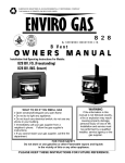
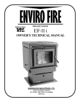
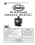
SHERWOOD INDUSTRIES IS AN ENVIRONMENTALLY RESPONSIBLE COMPANY
THIS MANUAL IS PRINTED ON RECYCLED PAPER
A C C E N T 25BV
By SHERWOOD INDUSTRIES LTD.
OWNERS MANUAL
WHAT TO DO IF YOU SMELL GAS
• Open windows/Extinguish any open flame
• Do not try to light any appliance.
• Do not touch any electrical switch; do not use any
phone in your building.
• Immediately call your gas supplier from a
neighbor's phone. Follow the gas supplier's
instructions.
• If you cannot reach your gas supplier, call the fire
department.
WARNING
If the information in this
manual is not followed exactly,
a fire or explosion may result
causing property damage,
personal injury or loss of life.
Installation and service must
be performed by a qualified
installer, service agency or the
gas supplier.
FOR YOUR SAFETY
Do not store or use gasoline or other Flammable vapors and liquids
in the vicinity of this or any other appliance.
PLEASE KEEP THESE INSTRUCTIONS FOR FUTURE REFERENCE.
SAFETY PRECAUTIONS
FOR SAFE INSTALLATION AND OPERATION OF YOUR "ENVIROGAS" HEATER,
PLEASE, CAREFULLY READ THE FOLLOWING INFORMATION:
• All "ENVIROGAS" gas-fired appliances must be
installed in accordance with these instructions.
Carefully read all the instructions in this manual first.
Consult the building authority having jurisdiction to
determine the need for a permit prior to commencing
the installation.
• To prevent injury do not allow anyone who is
unfamiliar with the operation to use the stove.
• To prevent injury, if the pilot or pilot and
burners have gone out on their own, open the
glass door and wait 5 minutes to air out
before attempting to re-light stove.
• NOTE Failure to follow these instructions could
cause a malfunction of the fireplace, which could result
in death, serious bodily injury, and/or property
damage.
• Failure to follow these instructions may also void
your fire insurance and/or warranty.
• Always keep the area around these appliances
clear of combustible material, gasoline or other
flammable vapors and liquids.
• These appliances should not be used as a drying
rack for clothing or for hanging Christmas stockings or
decorations.
GENERAL
• Installation and repair should be done by
a qualified service person. The appliance
should be inspected before use and at least
annually by a qualified service person. More
frequent cleaning may be required due to
excessive lint from carpeting, bedding
material, etc. It is imperative that control
compartments, burners and circulating air
passageways of the appliance be kept clean.
• Due to the paint curing on the stove a faint odor
and slight smoking will likely be noticed when the
stove is first used. Open a window until the slight
smoking stops.
• Always connect this gas stove to a vent system
and vent to the outside of the building envelope.
Never vent to another room or inside a building. Make
sure you use the vent pipe that is specified. Make sure
that the vent is properly sized and is of adequate
height to provide the proper draft. Inspect the venting
system annually for blockage and any signs of
deterioration.
WARNING: Failure to position the parts in accordance
with these diagrams or failure to use only parts
specifically approved with this appliance may result in
property damage or personal injury.
WARNING: Do not operate with the glass front
removed, cracked or broken. Replacement of the
glass should be done by a licensed or qualified service
person.
• Due to high temperatures the appliance
should be located out of high traffic areas and
away from furniture and draperies.
Children and adults should be alerted to
hazards of high surface temperatures and
should stay away to avoid burns or clothing
ignition.
• Young children should be carefully
supervised when they are in the same room
as the appliance.
• Never use solid fuels such as wood, paper,
cardboard, coal, or any other flammable liquids etc., in
this appliance.
• Do not use this heater if any part has been under
water. Immediately call a qualified service technician
to inspect the heater and to replace any part of the
control system and any gas control which has been
under water.
• Clothing or other flammable material
should not be placed on or near the
appliance.
FOR YOUR SAFETY
• Installation and service must be performed by a
qualified installer, service agency or the gas supplier.
• Do not abuse glass by striking or slamming door
shut.
• This installation must conform with local codes or,
in the absence of local codes with the current
CAN/CGA -B149 installation code in Canada or the
National Fuel Gas Code ANSI Z223.1 in the USA.
2
TABLE OF CONTENTS
SECTION
1.
2.
3.
4.
5.
6.
7.
8.
9.
10.
11.
12.
13.
14.
PAGE
3
5
6
7
8
9
10
11
12
13
14
15
16
17
Code Approvals
Dimensions and Clearances to Combustibles
Venting
Assembly and Installation Instructions
Electrical Requirements
Gas Line Connection and Testing
Installation of Log Sets and Embers and Brick Panels
Operating Instructions
Routine Maintenance and Service
Fuel Conversion
Trouble Shooting
Parts and Accessories
Warranty
Installation Data Sheet
1. CODES AND APPROVALS
VENTED type is identified by the suffix BV.
This appliance draws in room air for combustion and vent dilution
air.
•
These appliances have been tested by Intertek Testing Services. and found to comply with the established standards for
GAS FIRED VENTED ROOM HEATER in CANADA and the USA as follows:-
LISTED VENTED ROOM HEATER (EG 25 BV Nat. & LPG )
TESTED TO: ANSI Z21.88-1998
CSA 2.33.M98 VENTED GAS FIREPLACE HEATER
CANADA and U.S.A.
CERTIFIED FOR INSTALLATION FROM 0 - 2000 FT (810 M)
FOR INSTALLATIONS ABOVE 2000 FEET (810 m)
•
In Canada the unit must be derated by 10% for installation at elevations between 2,000 (810 m)and 4,500
feet (1370 m).
NATURAL GAS
PROPANE GAS
INPUT: 20814 (6.09 Kw) #44 DMS
•
INPUT: 22257 (6.52 Kw) #54 DMS
In the USA, these appliance are certified for elevations up to 2,000 feet (810 m). For elevations above 2,000
feet (810 m), input should be reduced 4% for each 1,000 feet (405 m) above sea level.
ACCENT 25
•
•
•
•
•
Has been certified for use with either natural or propane gases. (see rating label.)
Is not for use with solid fuels.
Is approved for bedroom or bedsitting room. (A thermostat must be installed in Canada.)
Must be installed in accordance with local codes.
If none exist use current installation code CAN/CGA B149 in Canada or ANSI Z223.1/NFPA 54 in the USA.
Must be properly connected to a venting system
WARNING: For installation only in a solid fuel burning fireplace with a working flue and
constructed of non-combustible material using a chimney liner kit.
3
CODES AND APPROVALS CONTINUED
RE: CONVERSION OF ZERO CLEARANCE FACTORY BUILT FIREPLACES
The following instructions cover Sherwood Industries Ltd. policy for Gas-Fired Appliances (inserts) to be retofitted
into existing factory built fireplaces with replacement parts removed.
GENERAL REQUIREMENTS
Background
A gas fired insert is approved for use in an existing masonry or a listed factory built fireplace without any
alterations. If the factory or masonry fireplace is altered its warranty is void.
Recent practice in the field is to remove parts that do not require cutting, bending or breaking from the factory
built fireplace in order to allow the insert to fit.
Sherwood Industries Ltd. Policy:
Intertek has approved listed factory built fireplaces, as a certified zero clearance kit provided that the following
conditions have been met.
1.
2.
3.
4.
5.
The removal of any part will not weaken the stuctural integrity of the factory built fireplace.
The factory built fireplace is in good condition.
There is no alterations in the form of cutting, bending, or breaking any parts.
Firebricks may be removed.
A permanent label must be supplied with the insertwith the instructions to affix it to the firebox of the
factory built fireplace. It will have the wording to the effect :
‘’WARNING- THIS FIRPLACE MUST ONLY BE OPERATED WITH A GAS INSERTREMOVAL OF THE INSERT AND THE USE OF SOLID FUEL IS PROHIBITED AND
MAY CAUSE A FIRE HAZARD"
REPLACEMENT PARTS INCLUDE:
Fire bricks, smoke sheild, flue damper, glass doors, and firescreens.
4
2. DIMENSIONS AND CLEARANCES TO COMBUSTIBLES
DISTANCE TO COMBUSTIBLES:
Mantel pillar to surround panel
2" / 5.08 cm
Floor to 8" wide mantel 40" / 101 cm
Minimum non-combustible surface in front of unit
8" / 20.8 cm
OTHER DIMENSIONS
A. Minimum Depth of unit into fireplace 16" / 41 cm
B. Depth of unit out of fireplace 1 / 2.54 cm
C. Minimum firebox size
(W 68.5 x H 55.8 x D 43.1 cm)
Maintain sufficient clearances for operation, service and maintenance
W 27" x H 22” x D 17"
3. VENTING
WARNING: THIS APPLIANCE HAS BEEN DESIGNED TO OPERATE BY DRAWING COMBUSTION AIR AND
DILUTION AIR FROM THE ROOM. IT IS ALSO DESIGNED TO DRAW ROOM AIR FOR PROPER HEAT CIRCULATION
FROM THE SIDES OF THE UNIT. BLOCKING OR MODIFYING THE LOUVERS IN ANY WAY CAN CREATE HAZARDOUS
SITUATIONS, EITHER THROUGH POOR VENTING OR BY OVERHEATING. IT IS IMPORTANT THAT THIS UNIT HAS
SUFFICIENT AIR CIRCULATION FOR PROPER VENTING AND COMBUSTION. PROVISIONS MUST BE MADE FOR THE
SUPPLY OF ADEQUATE COMBUSTION AND VENTILATION AIR. THESE OPENINGS MUST NOT BE BLOCKED. THE
APPLIANCE MUST NOT BE CONNECTED TO A CHIMNEY FLUE SERVICING A SEPARATE SOLID FUEL BURNING
APPLIANCE.
AUTOMATIC FLUE GAS SPILL SWITCH
NOTE: THIS HEATER MUST BE PROPERLY CONNECTED TO A VENTING SYSTEM. THIS HEATER IS EQUIPPED WITH
A VENT SAFETY SHUTOFF SYSTEM DESIGNED TO PROTECT AGAINST IMPROPER VENTING OF COMBUSTION
PRODUCTS. THIS SAFETY SWITCH IS LOCATED ON THE REAR OF THE APPLIANCE CLOSE TO
THE DRAFT HOOD RELIEF OPENING.IF THE SWITCH TRIPS MORE THAN ONCE THE VENTING SHOULD BE
INSPECTED BY A QUALIFIED SERVICE TECHNICIAN FOR POSSIBLE BLOCKAGE OR SEVERE DOWN DRAFT
CONDITIONS
The draft hood must be in the same pressure zone as the air inlet. To inspect draft from the front of the unit, Remove top
louvers by pulling up and out. Locate the 3/8” tube between the heat exchanger and top, check for a draft using smoke. A
vacuum or suction into the tube will indicate proper drafting.
This model can be vented with 4" aluminum or stainless steel flex vent and/or certified Type B Gas Vent. The flue collar of the
appliance will fit inside of a standard 4” vent and may be fastened directly to the vent.
Check periodically that the vent is unrestricted and an adequate draft is present when the unit is in operation.
5
3.VENTING FIREPLACE INSERTS
WARNING: Operation of this heater when not connected to a properly installed and
maintained venting system can result in carbon monoxide (CO) poisoning and possible death.
The Envirogas ACCENT 25 may be installed and vented into any solid fuel fireplace that has been installed in accordance with
the National, Provincial/State and local building codes and has been constructed of non-combustible materials.
An approved full length chimney liner and rain cap must be used. A throat connector or flashing must be installed, to ensure a
tight seal, top performance, safety and efficiency. Carefully follow the manufacturers instructions which accompany the
chimney liner kit.
Install sealed throat connector or flashing to prevent leakage of room air up through
chimney.
Measure the height of the chimney beforehand and purchase the appropriate kit.
Never attempt to over stretch a flexible liner to accommodate the height of the
chimney.
Make sure that all chimney clean outs are tightly fitting and will not permit air to leak
into the chimney.
The chimney must be clean, in good working order and constructed out of noncombustible materials.
Any flue damper must be removed or blocked permanently in the open position.
Remove the vent collar plate from the top of the insert and connect it securely with
sheet metal screws and/or hose clamps. Check for any tears in the liner at this
point. (See also Assembly and Installation Instructions section 3. )
IMPORTANT: The screws that hold the vent collar plate in it's approved position
must be installed.
PREPARATION FOR INSTALLATION
•
•
Remove the packaging from the appliance and surround panels, check to make sure there is no damage.
Carefully check the glass door. Do not use the unit if it is damaged. In the event damage is found please report it
to both the courier and your dealer as soon as possible.
Carefully clean the fireplace and flue before installing the stove. Failure to do so may result in fumes or dirt being
blown into the room and may cause a fire leading to death or serious injury.
6
4. ASSEMBLY AND INSTALLATION INSTRUCTIONS
ASSEMBLING AND INSTALLING YOUR ENVIROGAS ACCENT 25
1. Remove the unit from it’s box
DRAFT HOOD
2. Open the door, by first removing the cover with the nameplate
attached (open valve door and pull nameplate cover
ADJUSTMEN
T
SCREWS
side tab to release catch), undo the two bolts at the
bottom of the door. Lift the door up and out to remove.
CAUTION GLASS MAY SEPARATE FROM DOOR.
3. Remove log and ember set and all wrapping material
from the stove. Remove wrapping material from log
and embers and check for any damage. If damage is
observed do not use unit and contact your local dealer.
4. Measure the distance from the front of the fireplace
facing to the front of the flex liner in the chimney.
5. Loosen the two “adjustment” screws and adjust the
sliding exhaust channel to the dimensions measured in
STEP 1. Re-tighten screws.
6. Remove the front exhaust locating screw. Slide the
exhaust channel backwards from the unit. Properly
secure the exhaust channel to the 4“ flexible vent pipe
liner previously installed in the chimney using (3) three
sheet metal screws.. Be careful not to over stretch the
liner.
LEVELING LEGS
7. Place the unit part way into the fireplace. Connect the
fireplace insert's rigid gas line to the household gas
supply using locally approved methods. Place the
electric cable so it can be connected to the power supply.
Adjust the leveling legs
8. Slide the insert into the fireplace ensuring that the
exhaust channel is located under the slide rails on the top
of the fireplace insert.
9. Re-install the locating screw and tighten.
10. To assemble the surround panel, lay the panel face down
on a soft flat surface and place the brass trim on the
surround panel using the corner brackets supplied and
spring clips to hold trim to the surround panel.
11. Connect the surround panel wire harness terminal to the
stove wire harness terminal on the right side panel.
12. Place the assembled surround panel around the stove,
align the tabs with the slots in the front of the unit. Push
back then down to engage the surround slots on the mounting slots. Make sure the top surround panel sits
flat on the stove. If not use the leveling legs on the unit.
7
5. ELECTRICAL REQUIREMENTS
The ACCENT 25 will operate without electrical power. This model has a Millivolt gas control which uses the pilot flame to
generate enough electricity to operate the main burners. The appliance when equipped with blower must be electrically
connected and grounded in accordance with local codes or in the absence of local codes, with the current CSA C22.1
CANADIAN ELECTRICAL CODE Part 1, SAFETY STANDARDS FOR ELECTRICAL INSTALLATIONS, OR THE NATIONAL
ELECTRICAL CODE ANSI / NFPA 70 in the U.S.
WARNING:
Electrical
grounding instructions. This
appliance is equipped with a
three-prong (grounding) plug for
your protection against shock
hazard, and should be plugged
directly
into
a
properly
grounded three-prong outlet.
DO NOT cut or remove the
grounding prong from this plug.
CAUTION: Label all wires prior
to disconnection when servicing
controls. Wiring errors can
cause improper and dangerous
operation. Verify proper
operation after servicing
REMOVING / INSTALLING THE BLOWER
1.
Turn the unit off, open the door and remove the log set. Remove
brick panel(s) (see Removing and Installing Brick Panels). Remove
the burner tray assembly by removing the two (2) screws on either
side of the tray. Pull tray up at the back and lift out.
2.
Disconnect the gas line to the nipple. Remove the three (3) screws
holding the burner control tray to the back firewall. Lift tray up on left
side and pull out.
3.
Pull blower towards you. Disconnect wires from the blower and
remove.
4.
To re-install perform the preceding steps in reverse.
INSTALLING REMOTE THERMOSTAT OR WALL SWITCH
RECOMMENDED WIRE SIZE for thermostat installation: 18 gauge, 2 wire solid core, Low Voltage wire. (Bell wire)
1.
2.
Install the 18 Gauge wire supplied to the two terminals on the thermostat or remote wall switch.
Connect the other end of the wire to the gas valve using the two outside terminals on the front of the gas valve.
Use the terminals marked (TP/TH and TH).
RECOMMENDED MAXIMUM LEAD LENGTH (TWO WIRE)
WHEN USING WALL THERMOSTAT
MAXIMUM LENGTH
WIRE SIZE
14 GAUGE
100 FEET
16 GAUGE
64 FEET
18 GAUGE
40 FEET
20 GAUGE
18 FEET
8
6. GAS LINE CONNECTIONS and TESTING
WARNING: Only persons licensed to work with gas piping may make the necessary gas connections to this appliance.
GAS LINE CONNECTION
•
This stove is equipped with a 3/8 x 3 inch black iron nipple located on the right side of the unit terminating in a 3/8" male
NPT fitting. Consult your local authorities codes or the CAN/CGA B 149 (1 or 2) installation code in Canada, or in the USA
gas installations follow either local codes or the current edition of the National Fuel Gas Code ANSI Z223.1.
•
The efficiency rating of this appliance is a product thermal efficiency rating determined under continuous operating
conditions and was determined independently of any installed system.
The appliance and its shutoff valves must be disconnected from the gas supply piping system during any pressure testing
where the pressure exceeds 1/2 PSIG (3.45 kpa) or damage will occur to the valve.
The appliance must be isolated from the gas supply piping system by closing its individual manual shutoff valve during any
pressure testing of the gas supply piping system at test pressures equal to or less than 1/2 psig (3.5 kPa).
Always check for gas leaks with a soap and water solution after completing the required pressure test.
TO TEST VALVE PRESSURES
The pressure taps are located on the left side of the valve
•
•
•
•
Turn set screw 1 turn counter clockwise to loosen,.
Place 5/16" (8 mm) I.D. hose over pressure tap system.
Check pressures using a manometer.
When finished, release pressure, remove hose & tighten set screw.
Pilot Adjustment Screw
Gas Control Knob
Hi Low Knob
3/8” Pipe
Manifold Pressure Tap
Inlet Pressure Tap
ORIFICE SIZES, PRESSURES AND BTU'S
All models are equipped with a variable output gas control.
MAIN BURNER ORIFICE:
Manifold Press:
Min. Manifold Press:
Max. Supply Press:
Min. Supply Press:
Max. BTUH Input:
Min. BTUH Input:
Output
NATURAL
#42 DMS
PROPANE
#53 DMS
3.8"wc / 0.95 kpa
1.1"wc / 0.27 kpa
7.0"wc / 1.74 kpa
5.0"wc / 1.25 kpa
25,000 btu/h/ 7.32 Kw
12,500 btu/h/ 3.66 Kw
Fan on 18,875 btu/h/ 5.53kw
Fan off 18,000 btu/h/ 5.27 kw
11.0"wc / 2.74 kpa
2.7"wc / 0.67 kpa
12.0"wc/ 2.98 kpa
11.5"wc / 2.86 kpa
25,000 btu/h/ 7.32 Kw
12,500 btu/h/ 3.66 Kw
Fan on, 19,250 btu/h/ 5.64kw
Fan off 18375 btu/h/ 5.38kw
NEVER USE AN OPEN FLAME FOR LEAK TESTING
9
7. INSTALLATION OF LOGS, EMBERS and BRICK PANELS
INSTALLING THE GLOWING EMBERS and LOGSET
A bag of ceramic fiber embers is provided for use on the
burner PAN.
REMOVING AND INSTALLING THE BRICK PANELS
CAUTION: Use only the type of ember material supplied
with this appliance. Due to the irregular size of the ember
material there may be more than required. Use only a
single layer. Do not pile embers. The use of other foreign
materials on the burners may create dangerous conditions.
Optional ceramic panels: Remove burners. Gently pull
right brick side panel inwards from the bottom back. Pull
towards the back then out freeing it from the front retainer.
Caution pilot may damage panel. Remove the left side
panel the same way. Remove the back panel from ledge.
If over time, through cleaning and servicing, these embers
require replacement, contact your nearest ENVIROGAS
dealer for replacement embers.
To install, place back panel on ledge. Insert front edge of
brick panel into the retainer and very gently move panel
forward and out until flush against firebox side. Repeat for
other side.
1.
Open the door. Remove the log set.
Carefully remove log from unit. Check to ensure there
is no damage. It is very important to install this log in
its proper position to insure safe, optimum operating
conditions.
2.
Place the log set into the firebox with the burnt area
forward. Locate the log by seating it down onto the
burner tray supports already installed.
3.
Gently remove the ember material from the plastic
bag. Place a single line of embers on burner as
shown beside.
4.
Carefully avoid any clumping or large build ups. Do
not pack down, leave embers loose
5.
Upon the first light up, watch for ignition to all burner
ports. If a long delay is noted:
First, wait for the appliance to cool down
•
Open the front door of the appliance.
•
Check to carefully reposition the embers making
sure that burner ports are not plugged solid or
blocked
CAUTION: NEVER OPERATE THIS APPLIANCE WITH
THE DOOR REMOVED
Place ember material in the shaded area
only. Do not pack ember material down.
10
8.OPERATING INSTRUCTIONS
FOR YOUR SAFETY READ BEFORE OPERATING
WARNING: IF YOU DO NOT FOLLOW THESE INSTRUCTIONS EXACTLY, A FIRE OR EXPLOSION
MAY RESULT CAUSING PROPERTY DAMAGE, PERSONAL INJURY OR LOSS OF LIFE.
A) This appliance is equipped with a pilot, which must
• If you cannot reach your gas supplier, call the
be lit by hand by following these instructions exactly.
fire department.
B) BEFORE LIGHTING smell all around the appliance C) Use only your hand to push in or turn the gas
area for gas, and next to the floor because some
control knob. Never use tools. If the knob will not
gas is heavier than air and will settle on the floor.
push in or turn by hand, do not try to repair it . Call
WHAT TO DO IF YOU SMELL GAS:
a qualified service technician. Force or attempted
repair may result in a fire or explosion.
• Do not try to light any appliance.
D) Do not use this appliance if any part has been
• Do not touch any electrical switch; do not use
under water. Immediately call a qualified service
any phone in your building.
technician to inspect the appliance and to replace
• Immediately call your gas supplier from a
any part of the control system and any gas control
neighbor’s phone. follow the gas supplier’s
which has been under water
instructions.
LIGHTING INSTRUCTIONS
If the pilot will not
stay lit after several
tries, turn the gas
control knob to
3. Turn the gas control knob
“OFF" and call you
clockwise to the “off’ position.
service technician
4. Open door. Wait five (5) minutes to clear out any or gas supplier.
gas. Close door. If you smell gas including near
the floor, STOP! Follow “B” in the above safety
information.
If you don’t smell gas go to next step.
5. Find the pilot located to the right between the front
and rear burner.
6. Turn gas control knob
counter-clockwise to “PILOT”.
7. Push the gas control knob in fully and hold.
Immediately light the pilot by pushing the piezo
spark igniter. Keep knob depressed for about 30
seconds after pilot is lit. Release knob. If pilot
goes out, repeat steps 4 through 6.
WARNING The gas valve has a lockout device, which
HI \ LO knob
Control knob
will not allow the pilot burner to be re-lit until the
thermocouple, has cooled.
If the knob does not pop up when released, stop and 8. Turn gas control knob counter-clockwise to the
“ON” position.
immediately call your service technician or gas
Flip burner switch to “ON” then turn “HI / LO” knob
supplier.
to the desired setting.
NOTE: Check to be sure the pilot flame engulfs the
9. Turn on all electrical power to the unit
thermocouple and that the burners light
completely.
1. STOP! Read the safety information above.
2. Turn off all electrical power to the appliance.
TO TURN OFF GAS TO
APPLIANCE
1. Turn the gas control knob
clockwise to “OFF” DO NOT FORCE
2. Turn off all electrical power to the appliance if service is to be performed.
3. Flip burner switch to off.
11
9. ROUTINE MAINTENANCE and SERVICE
After carefully replacing the log and embers in their correct
positions, and the door has been resealed, re-light the
pilot, following the instructions on the attached label.
Periodically check to ensure that your system is clean.
Periodically check the pilot and burner. Check to see that
all the burner ports are clean and clear. Check the pilot
head for blockage. Check to ensure the pilot flame is blue
with yellow tips.
CLEARANCES MUST BE SUFFICIENT TO ALLOW
ACCESS FOR MAINTENANCE AND SERVICE
NOTE: Wipe the gold louvers with a soft cloth
before firing unit. If left, fingerprints can become
etched in the gold.
OPENING THE DOOR
Depending upon the amount of use, cleaning should be
required no more than two or three times per season.
Turn unit off and wait until the appliance has cooled down.
1.
Shut of gas supply to appliance.
Open the lower louver panel. Undo the two bolts at the
bottom corners of the door. Swing door out, then lift up
and out to remove.
2.
Remove surround panels by pulling up then out.
disconnect gas line from the valve. Disconnect
harness at connector on side of unit.
Ensure the door is properly fastened after cleaning before
attempting to re-light the appliance.
3.
Open the door and remove the log. Remove the
burner tray assembly by removing the two screws on
either side of the tray. Pull tray up at the back, lift tray
out and towards the front.
4.
Remove the brick panel as per instructions. Undo the
three screws that hold the burner control tray onto the
back firewall. Lift control tray up on the left side and
pull out. Remove wire connector from firebox.
5.
Installation is the reverse
REMOVING BURNER CONTROLS:
CLEANING THE GLASS
Do not clean glass when hot
It will be necessary to clean the ceramic glass periodically.
During a cold start up, condensation will sometimes form
on the glass, this is a normal condition with all gas
fireplaces and stoves. However, this condensation can
allow dust and lint to cling to the glass surface. Initial paint
curing of the appliance can leave behind a slight film on
the glass. This is a temporary problem. It is therefore
recommended that the glass be cleaned initially after
about the first two weeks of use.
Caution:
Bleed lines before lighting and light
pilot with door open
To clean the door use a mild glass cleaner and a soft
cloth. Abrasive cleaners will damage the glass and
gold surfaces.
ADJUSTING VENTURI AIR SETTINGS
TO REPLACE DOOR GLASS
The glass in this appliance is 5 MM ceramic. If the glass is
damaged or broken a factory replacement must be fitted.
To Replace:
•
Open door, remove the glass carefully.
•
Install the new piece of glass with the large bulb in the
gasket tape against the unit. Place the joint in the
tape in a bottom corner. Close door
Glass must be purchased from an Envirogas dealer.
No substitute materials are allowed.
There is one venture and one air shutter on this
appliance.
The venture has been set for installations at sea level.
Some adjustment could be required.
CLEANING THE INSIDE OF THE FIREBOX
Remove the log carefully from the firebox. Gently remove
the embers and place on a piece of paper towel. Until
ready to replace.
•
Vacuum the bottom of the firebox thoroughly. Carefully
clean off any dust on the logs and brick panels and
remove any lint from the main burner and pilot burner.
12
To adjust for high altitude: open the lower louvers,
locate the venturis between the burner and control
trays. Loosen the set screws with a long screwdriver
and rotate the air shutter until an efficient flame is
achieved.
10.FUEL CONVERSION
“Warning” This conversion kit shall be installed by a qualified service technician in accordance with the
manufacturer’s instructions and all applicable codes and requirements of the authority having
jurisdiction. If the information in these instructions is not followed exactly, a fire, explosion or CO
poisoning may result. The qualified service agency is responsible for the proper installation of this kit.
The installation is not proper or complete until the operation of the converted appliance is checked as
specified in the owner’s conversion kit.
Please read and follow these instructions. Also please read the instruction guide lines provided by S.I.T on how to
remove and install the HI-LOW regulator.
STEP 1. Carefully inspect all parts supplied with this conversion kit.
STEP 2. Shut the gas off and disconnect the main gas line from the unit.
STEP 3. Open the door by undoing the two screws on the bottom of the door, pull door towards you then lift up
and out. Remove the logs and the burner tray from the unit, this will expose the main burner orifice and
the pilot assembly
STEP 4. Change the regulator on the front of the gas valve. (Follow the instructions provided by S.I.T)
STEP 5. To change the pilot orifice: First, pull the pilot head of the pilot assembly, using a 5/16” allen key
remove the pilot injector for assembly. Install the new pilot injector for the fuel being used.
(BE CAREFUL WHEN TIGHTENING THE PILOT FITTING, YOU COULD BREAK THE CERAMIC IGNITER
ELECTRODE).
STEP 6. Re-install the pilot assembly in the reverse order of STEP 5.
STEP 7. Remove the main burner orifice using a ½” deep socket
STEP 8. Install the new orifice supplied. Be sure to put a bead of pipe thread sealant or approved Teflon tape on
the orifice before installing the orifice into the burner assembly.
STEP 9. Re-install the burner tray in unit, log set and door.
STEP 10. Reconnect the gas line to the unit. Do a leak check using a soap and water solution or an approved
manner on the gas supply line and the pilot tubing.
STEP 11. Re-light the appliance to insure proper operation and proper flame appearance. Be sure to adjust the
venturi setting to achieve an efficient flame in the fireplace.
STEP 12. MAKE SURE that the sticker provided by S.I.T is installed to signify that this valve has been converted
to a different type of fuel. Also make sure that the rating plate has a conversion label to show that this
unit has been converted to a different fuel type.
A VISUAL CHECK OF THE REGULATOR KNOB IS NECESSARY TO DETERMINE WHETHER OR NOT THE
REGULATOR IS THE CORRECT PART. A 50% TURN DOWN REGULATOR WILL HAVE ONLY ONE
CORNER ON THE KNOB.
CONVERSION KIT PARTS LIST
1 50% turn down HI-LOW Regulator w 3 T-20 Torx
screws
1 pilot injector
1 Main orifices
1 Pilot assembly mounting gasket
Pilot Orifice
Burner Orifice.
NATURAL GAS
.62-mm
# 42 DMS
Venturi Settings
13
1/16” open
PROPANE.
.35-mm
#53 DMS
3/8” open
11. TROUBLE SHOOTING
Problem
Spark will not arc to the pilot after
repeated pressing of spark ignitor
Possible Cause
Defective piezo ignitor
Solution
Check connections to ignitor
-If ignitor connections are good but there is no
spark-replace ignitor
Broken spark electrode
-Check for broken ceramic insulation
replace, electrode if broken
Miss-aligned spark electrode
-If spark is not arcing from the electrode to pilotadjust by loosening screws on pilot base.
Adjust away from burner and re-tighten
Problem with thermocouple circuit
-Check for proper connection of thermocouple
to rear of valve. If loose, tighten lightly
-Check pilot for full flame impingement around
thermocouple. If the pilot is to small - Check
gas pressure, adjust pilot rate screw, check pilot
head for blockage.
-Check thermocouple voltage at rear of valvemust be greater than 5 mV. If low , replace
thermocouple.
Air in gas line - (Pilot flame dies while
knob is depressed.)
-Bleed line.
-Check gas line pressure.
-Contact dealer.
Burners will not remain lit
Problem with thermopile circuit
-Check gasline pressure.
-Check for flame impingement on thermopile, if
low see “Pilot will not stay lit”
-Check thermopile for a Minimum of 300 mV
when burner switched on.
-Check wiring to thermostat for breaks.
BV only: - Check for spillage at draft hood that
may trip spill switch.
Flame lifting
- Leak in vent pipe
- Improper vent configuration
- Terminal may be recirculating flue
gases
-check for leaks in vent connections
-check vent configuration with manual
-check to see if terminal is on correctly
-May need to install high wind termination cap
-contact dealer.
BV only: insufficient air for
- Air tight house
- A Vacuum in room due to other air
moving device
- supply make up air to the unit.
Pilot will not remain lit
combustion
Glass fogs up
Normal conditions - after the appliance warms up glass will clear
** Due to additives in gas, glass may get hazy during normal use**
Clean when needed.
Blue flames
Normal during start - flame will yellow as the appliance heats up.
Flames are burning “dirty” or Sooting
Flame impingement
-check log position
-increase primary air by opening venturi
shutters
see also “Burners will not stay lit”
14
12. PARTS AND ACCESSORIES
Service Parts available from your local Envirogas Dealer.
PART #
DESCRIPTION
EG25-001
EG25-002
EG25-003
EG25-004
EG25-008
EG25-014
EG25-015
EG25-018
EG25-026
EG25-030
EG25-031
EG25-032
EG25-035
EG25-036
EG25-040
EG25-041
EG25-042
EG25-043
EG25-044
EG25-052
EG25-053
EG25-062
EG25-065
EG25-070
EG25-072
EG25-073
EG25-074
EG25-075
EG25-088
EG25-089
EG25-090
EG25-092
EG25-110
EG25-114
EG25-115
EG25-200
EG25-202
Convection Blower
Heyco Strain Relief
Fan Controller with Knob
Hi-Temperature Electrical Cord
Burner Switch
120°F Ceramic Auto Reset n/o Temp Sensor (big foot)
300°F Temp Sensor n/c Ceramic (spill switch)
Wire Harness
Valve Access Door Magnet
Blank Orifice
Thermocouple
Ignitor electrode
S.I.T Piezo Ignitor
Ignitor Cable
Thermopile
SIT Nova 820 Valve (NG) 50% turndown
SIT Nova 820 Valve (LPG) 50% turndown
NOVA Pilot with Ignitor Electrode, Natural Gas
NOVA Pilot with Ignitor Electrode, Liquid Propane
Burner Controls Complete (NG)
Burner Controls Complete (LPG)
3” x 3/8” Black Iron Pipe Nipple
Burner Tray
ENVIROGAS EG25 Nameplate
Log Set & Embers
Embers
Brick Panels. (Ceramic)
Brick Panel ( Metal)
Valve Gaskets
Window channel tape
Glass with Gasket
Painted Door
Regular Size Surround Panel
Brass Surround Trim
Louver set GOLD (Top and Bottom)
LP to NG Conversion Kit
NG to LP Conversion Kit
15
120° F (49° C)
FAN
TEMPERATURE
SENSOR
DRAFT HOOD
SLIDER
EC-001
FULLY
ASSEMBLED
PILOT
EC-015 NG
EC-016 LP
300° F
(149° C)
SPILL
SWITCH
CERAMIC
BRICK
LINERS
EC-012
THERMOCOUPLE
PAN BURNER
POST APR 2000
EG25-074
EC-003
THERMOPILE
BRICK CLIPS
AND BACK
LEDGE
EC-009
SPARK
ELECTRODE
EC-011
BLACK IRON
NIPPLE
EG25-062
LEVELING
LEGS X 2
LOUVER SET
(TOP & BOTTOM)
EG25-115
PIEZO
IGNITER
RATING
LABEL
PLATE
PAINTED
DOOR
EC-023
EG25-092
CONVECTION
BLOWER
MOUNT
EC-028
CONVECTION
BLOWER
EC-069
MAIN
BURNER
ORIFICE
EC-022
SIT NOVA 820
GAS VALVE
EC-006 NG
EC-007 LP
ACCENT 25 DOOR
COVER
ACCENT 25 INSERT
EXPLODED VIEW
PAGE 2 of 2
VALVE
MOUNT
JUNE 2002
GOLD- 50-009
NICKEL 50-010
ON / OFF /
THERMOSTAT
SWITCH
BURNER
SWITCH
BRASS TRIM
CORNER
BRACKETS
EC-026
(NOT SHOWN)
EC053
FAN
CONTROLLER
EC-039
ACCENT 25
OVERSIZE
SURROUND WITH
FPI WIRING
HARNESS
PART (A)
PAINTED TRIM
50-108
BRASS TRIM
ACCENT 25
50-013
REGULAR
SURROUND WITH
TRIM
NICKEL TRIM
50-014
PAINTED TRIM
50-107
BRASS TRIM
50-011
NICKEL TRIM
50-012
ACCENT 25
EXPLODED VIEW
SURROUND PANELS
PAGE 1of 2
JUNE 2002
17
EC-034
(NOT SHOWN)
13. WARRANTY
Sherwood Industries Ltd. offers a *Lifetime Warranty on this gas product. The lifetime warranty covers the appliance for a
period of seven years from the date of installation. This warranty applies only to the original owner in the original location
Covered under the lifetime warranty are Cabinet Sides, Tops, Pedestals, Surround Panels and Chassis and Heat Exchanger.
These steel components are covered against manufacturer’s defects for 5 years and labor for the first year and for parts only
thereafter.(A) The following exclusions apply:- over-firing due to incorrect setup or tampering, damage caused by incorrect
installation, usage or abuse. The unit must be properly installed by a qualified technician or installer, and must meet all local
and national gas and building code requirements.
We also cover against manufacture defects under our lifetime warranty. The following components,
Gold Plating, Log Set, Burners and Glass (A) The following exclusions apply: Gold plating- Damage caused by scratching,
marring, chemicals, fingerprints, abrasive cleaners or discoloration with age. Glass- use of harsh or abrasive cleaners, striking
the glass or surface contaminates. Logset- Damage caused by incorrect handling or misuse. Burners- damage caused by
improper or continuous operation under incorrect conditions.
Sherwood Industries Ltd. offers a 2-year warranty on all the Electrical Components and Gas Components against
manufacturing defects. Paint is covered against flaking. This offer includes parts and labor for 1 year and for parts only
thereafter.
The paint on the Metal Brick Liner may peel. This is due to the extreme conditions applied to the paint and is no way covered
under warranty.
Your dealer shall make all claims under this warranty in writing.
(A): TO A MAXIMUM OF SEVEN YEARS
WHEN FILING A WARRANTY CLAIM PLEASE COMPLETE THE FOLLOWING
INFORMATION ON AN OFFICIAL WARRANTY CLAIM FORM:
To the Dealer
•
Name, address and telephone number of purchaser and date of purchase.
•
Date of installation. Name of installer and dealer. Serial number of the appliance. Nature of complaint, defects or
malfunction, description and part # of any parts replaced.
To the Distributor
• Sign and verify that work and information are correct.
This warranty covers defects in materials and workmanship only if the product has been installed according to the manual’s
instructions. If the product is damaged or broken as a result of misuse or mishandling the warranty does not apply. The
warranty does not cover removal and re-installation costs.
Sherwood Industries Ltd. reserves the right to repair or to replace the defective product. The shipping costs are to be paid by
the consumer. All warranties by the manufacture are set forth herein and no claim shall be made against the manufacturer on
any oral warranty or representation.
Sherwood Industries Ltd. and its employees or representatives will not assume any damages, either directly or indirectly
caused by improper usage, operation, installation, servicing or maintenance of this appliance.
Sherwood Industries Ltd. reserves the right to make changes without notice. Please complete and mail the warranty
registration card and have the installer fill in the installation data sheet in the back of the manual for warranty and future
reference.
14. INSTALLATION DATA SHEET
The following information must be recorded by the installer for warranty purposes and future reference.
Envirogas Model:
ACCENT 25 BV
Name of Owner:
Name of Dealer:
__________________________________________
___________________________________________
Address:
Address:
__________________________________________
___________________________________________
__________________________________________
___________________________________________
__________________________________________
___________________________________________
Phone:_____________________________________
Phone:
•
Model :___________________________________
•
Serial Number: __________________
•
Date of Purchase:
Name of Installer:
___________________________________________
Address:
___________________________________________
__________/________/________
•
___________________________________________
Date of Installation:
___________________________________________
__________/________/________
•
____ Natural Gas (Nat.), ____ Propane (LPG)
•
Inlet Gas Supply Pressure: ________ in.w.c.
___________________________________
Phone :_____________________________________
If the orifices were changed by the installer.
•
Front Burner Orifice # __________ ,
Back Burner Orifice # ________ .
•
Pilot Orifice # ________ or ______ in.Dia.
Installer's Signature
WEB SITE ADDRESS ( www.Envirofire.biz )
8/28/2002
MANUFACTURED BY:
SHERWOOD INDUSTRIES, 6782 OLDFIELD RD., SAANICHTON, B.C., CANADA V8M 2A3
19