1
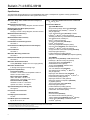
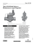
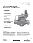
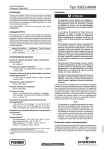
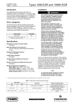
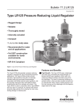
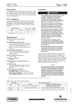
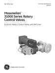
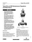
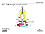
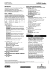
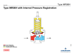
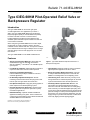
Bulletin 71.4:63EG-98HM
December 2014
Type 63EG-98HM Pilot-Operated Relief Valve or
Backpressure Regulator
Introduction
The Type 63EG-98HM can be used for gas, liquid
or steam applications. For applications up to 550°F /
288°C, the Type 63EG-98HM utilizes high temperature
Ethylenepropylene (EPR) or Perfl uoroelastomer (FFKM) for Class VI shutoff. If used in a corrosive service,
Perfl uoroelastomer (FFKM) and other elastomers are available options that offer superior resistance to heat and
most corrosive chemicals.
When using the Type 63EG-98HM with a corrosive liquid,
usually water or a water-containing solution, the valve
materials must be selected with care. For aqueous solutions,
use a Stainless steel linear cage or Whisper Trim™ III Cage
and body fl ange to ensure valve plug travel on a corrosionfree surface.
The Type 63EG-98HM is not an ASME certifi ed device.
W6866
Features
• Variety of Construction Materials—WCC steel and
CF8M Stainless steel are standard constructions.
Alloy 20, Hastelloy® C and Monel® are available options
upon request.
Figure 1. Type 63EG-98HM Pilot-Operated Relief Valve or
Backpressure Regulator
• Low Build-up Capability—Minimal build-up pressure is
required for main valve to achieve wide-open fl ow.
• Tight Shutoff—Elastomer seats for Class VI shutoff on
high temperature applications to 550°F / 288°C.
• Chemically Compatible Elastomers—
Perfl uoroelastomer (FFKM) is available for corrosive chemical applications.
• Easily Converted to Differential Control—The pilot
is ready for differential backpressure control with the
addition of a sealing washer on the adjusting screw.
• No Assembly Adjustments Required—Precise
machining ensures that the main valve plug shuts off at
both the port and upper seals at the same time.
• Labor-Saving Trim—Main valve body can stay in-line
during maintenance. Tested trim packages can be made
up and stocked ahead of time for fast replacement.
• Fast Speed of Response—High gain piloting system for
faster response than standard piloting system.
• Versatility in Both Liquid and Gas Service—The
pilot exhaust port and standard tapped pilot spring
case each come with removable vent for remote piping
when necessary. The standard tapped pilot spring case
comes with an optional gasketed closing cap that permits
pressure loading for remote pneumatic adjustment of the
set pressure. For remote upstream registration, the pilot
supply tubing may be disconnected at the 1/4 NPT main
valve body tapping and this tapping plugged.
• Excellent Overpressure Protection—Superior pump
bypass regulator for overpressure protection in pump
recirculation applications.
• NACE Availability—Optional materials available for
applications handling sour gases. These constructions
comply with recommendations of the NACE International
standards MR0175 and/or MR0103.
D102628X012
Hastelloy® C is a mark owned by Haynes International, Inc.
Monel® is a mark owned by Special Metals Corporation
www.fisherregulators.com
Bulletin 71.4:63EG-98HM
Specifications
This section lists the specifications for Type 63EG-98HM relief valves or backpressure regulators. Factory specification is
stamped on the nameplate fastened on the regulator at the factory.
Main Valve Body Sizes and End Connection Styles(1)(2)
See Table 1
5/64 in. / 2.00 mm Fixed Bleed Restriction Coefficients
Cg: 4.8; Cv: 0.14
Maximum Design Pressure(3)
600 psig / 41.4 bar or body rating limit, whichever is lower
Construction Materials
Maximum Operating Relief (Inlet) Pressure
Including Build-up(2)(3)
450 psig / 31.0 bar or body rating limit, whichever is lower
Type 63EG Main Valve
Body and Body Flange: WCC steel (standard),
CF8M Stainless steel, Hastelloy® C, Monel® or
Alloy 20 (optional)
Cage: 316 Stainless steel (standard), 416 SST,
Hastelloy® C, Monel® or Alloy 20 (optional)
Seat Ring and Valve Plug: 416 Stainless steel (standard),
316 Stainless steel, Hastelloy® C,
Monel® or Alloy 20 (optional)
Spring: Zinc-plated steel (standard) or
Inconel® X750 (optional)
Piston Ring: Polytetrafluoroethylene (PTFE)
Pipe Plug: Steel (standard), 316 Stainless steel, Hastelloy® C, Monel® or Alloy 20 (optional)
O-rings and Seals: Fluorocarbon (FKM) (standard), Ethylenepropylene (EPR) or
Perfluoroelastomer (FFKM) (optional)
Gaskets: Composition (standard) or Graphite (optional)
Type MR98H
Body: WCC steel (standard), CF8M Stainless steel,
Hastelloy® C, Monel® or Alloy 20 (optional)
Spring Case: WCC steel (standard) or
CF8M Stainless steel (optional)
Spring: Steel (standard), Stainless steel,
Inconel® X750 (optional)
Trim: 416 Stainless steel (standard),
316 Stainless steel, Hastelloy® C, Monel® or
Alloy 20 (optional)
Diaphragm: 302 Stainless steel (standard),
Ethylenepropylene (EPR), Hastelloy® C, Monel® or
Fluorocarbon(3) (FKM) (optional)
Diaphragm Protector: PTFE (optional)
Diaphragm Gaskets: Composition (standard)
or graphite (optional)
Seat: Fluorocarbon (FKM) (standard),
Ethylenepropylene (EPR) or
Perfluoroelastomer (FFKM) (optional)
Adjusting Screw Sealing Washer for Pressure
Loaded Pilot: Fluorocarbon (FKM)
Mounting Parts
Restrictor: Steel (standard),
316 Stainless steel or Monel® (optional)
Tubing: Stainless steel (standard) or Monel® (optional)
Fittings: Steel (standard), 316 Stainless steel
or Monel® (optional)
Maximum Outlet Pressure(2)(3)
450 psig / 31.0 bar
Maximum Differential Pressure(2)
400 psig / 27.6 bar
Port Diameter and Valve Plug Travels
See Table 2
Relief Set Pressure/Backpressure Control Ranges(4)
See Table 3
Flow Coefficients
See Table 4
Main Valve IEC Sizing Coefficients
See Table 5
Differential and Build-up Pressure Requirements(2)
See Table 6
Main Valve Flow Characteristics
Linear (standard) or Whisper Trim™ III Cage (optional)
Main Valve Flow Direction
In through seat ring and out through cage
Temperature Capabilities(2)
Fluorocarbon (FKM):
0 to 300°F / -18 to 149°C Not acceptable in water or steam in excess of 200°F / 93°C
Ethylenepropylene (EPDM):
Steel: -20 to 350°F / -29 to 177°C
Stainless steel: -40 to 350°F / -40 to 177°C
Perfluoroelastomer (FFKM):
Standard: 0 to 450°F / -18 to 232°C
Optional: 0 to 550°F / -18 to 288°C
Approximate Weights (Including pilot)
See Figure 4
Pilot Control Line Connection
1/8 NPT
Pilot Spring Case Connection
1/4 NPT
Pilot Wide-Open Flow Coefficients
Cg: 98; Cv: 2.75; C1: 35
1. Other ratings and end connections can usually be supplied; consult the local Sales Office.
2. The pressure/temperature limits in this bulletin and any applicable standard limitation should not be exceeded.
3. Fluorocarbon (FKM) diaphragm is limited to 300 psig / 20.7 bar.
4. Set pressure is defined as the pressure at which the pilot start-to-discharge.
Hastelloy® C is a mark owned by Haynes International, Inc.
Inconel® and Monel® are marks owned by Special Metals Corporation.
2
Bulletin 71.4:63EG-98HM
Pilot Control
Spring
TYPE MR98H
PM O C
CONTROL LINE
(MUST BE AT LEAST
3/8 IN. / 9.52 mm TUBING)
PILOT EXHAUST
(PIPE DOWNSTREAM
IF MINIMUM DIFFERENTIAL
IS MET)
Pilot Valve Plug
TYPE 63EG
FIXED RESTRICTION
Main valve spring
A6926_2
E
INLET
PRESSURE
INLET
PRESSURE
OUTLET PRESSURE
OUTLET PRESSURE
ATMOSPHERIC PRESSURE
ATMOSPHERIC
LOADING
PRESSURE PRESSURE
Main valve plug
LOADING PRESSURE
INTERMEDIATE PRESSURE
PILOT
SUPPLY
PRESSURE
Figure 2.
Operational
Schematic
VACUUM PRESSURE
TANK PRESSURE
VAPORof
PRESSURE
Principle
Operation
RELIEF PRESSURE
As longBOOST
as inlet pressure
remains below set pressure, the
PRESSURE
pilot control spring keeps the pilot valve plug closed. This
pressure provides the loading pressure that helps the main
valve spring keep the main valve plug tightly shut off.
Note: On an actual Type 63EG-98HM, the pilot spring case points downstream.
An inlet pressure rise above the set pressure overcomes the
pilot control spring and opens the pilot valve plug. Loading
pressure bleeds out the pilot exhaust faster than it can be
replaced through the restriction. This permits inlet pressure
to unbalance the main valve plug and open the main valve.
As inlet pressure drops back to set pressure, the pilot control
spring closes the pilot valve plug. Loading pressure again
builds up to close the main valve plug.
Example Sizing Problem:
To have a pump recirculation of oil and hold backpressure.
The pump capacity is 180 GPM / 681 l/min, the oil has a
specific gravity (G) of 1.00 and the temperature is ambient.
P1 (Inlet Pressure) = 25 psig / 1.7 bar
P2 (Outlet Pressure) = 15 psig / 1.0 bar
Q (Flow) = 180 GPM / 681 l/min
Calculated Cv = 57
The differential pressure (P1 – P2) is 10 psig / 0.69 bar. From
Table 4, it is determined that NPS 2 / DN 50 main valve has
the needed capacity. The pilot exhaust is piped downstream
of the valve. With the pipeline size equaling the valve body
size and using a linear cage, the Cv is equal to 63.3 as
shown in Table 4. Since the differential pressure is less than
40 psig / 2.8 bar, Table 5 verifies that the yellow main valve
spring can be used. To maintain the best accuracy, always
use the lightest spring rate available. The pressure buildup to a wide-open state is 7 psi / 0.48 bar over setpoint.
The setpoint on a relief valve or backpressure regulator is
defined as when the pilot begins to bubble or open. Since
the setpoint is 25 psig / 1.7 bar and the build-up required to
fully open the regulator is 7 psi / 0.48 bar, the total upstream
pressure would be at 32 psig / 2.2 bar. The differential
pressure between P1 – P2, 32 – 15 psig / 2.2 – 1.0 bar, is
17 psi / 1.2 bar.
3
TO OR GREATER THAN SETPOINT)
Bulletin 71.4:63EG-98HM
Table 1. Body Sizes and End Connection Styles
Main Valve Body Size
NPS
DN
Table 2. Port Diameters and Valve Plug Travels
Body Size
End Connection Style
Port Diameter
Valve Plug Travel
NPS
DN
In.
mm
In.
mm
50
NPT, ASME CL150 RF, CL300 RF,
CL600 RF or PN 16/25/40 flanged
2
50
2-3/8
60
1-1/8
29
80
3-3/8
86
1-1/2
38
3, 4, 6
80, 100, 150
ASME CL150 RF, CL300 RF,
CL600 RF or PN 16/25/40 flanged
3
4
100
4-3/8
111
2
51
150
7-3/16
183
2
51
8x6
200 x 150
ASME CL150 RF, CL300 RF
and CL600 RF flanged
6
8x6
200 x 150
7-3/16
183
2
51
2
Table 3. Relief Set Pressure or Backpressure Control Ranges
CONTROL PRESSURE RANGE(1)
Part Number
Color
1.0 to 2.4
ERCA04288A0
psig
bar
15 to 35
spring Free Length
spring Wire Diameter
In.
mm
In.
mm
Yellow
2.50
63.5
0.207
5.26
25 to 75
1.7 to 5.2
ERAA01910A0
Green
2.595
65.9
0.234
5.94
70 to 140
4.8 to 9.7
ERAA01911A0
Red
2.44
62.0
0.283
7.19
130 to 200
9.0 to 13.8
ERAA02889A0
Blue
2.250
57.2
0.331
8.41
150 to 375(2)
10.3 to 25.9(2)
1N943427142
Unpainted
5.063
129
0.394
10.0
1. All springs may be backed off to 0 psig / 0 bar. However, highest capacities and best performances are obtained by using these springs in their recommended ranges.
2. 150 to 375 psig / 10.3 to 25.9 bar spring range is for the Type MR98HH pilot construction.
However, the next consideration is making sure there is
enough differential pressure between P1 and P2 to fully open
the main valve. This minimum differential is determined by
the valve plug area and the main valve spring. The smaller
the valve plug area (i.e. body size) and the heavier the spring
rate (i.e. red spring), the larger the differential requirements.
In Table 5 the yellow main valve spring for NPS 2 / DN 50
body requires a differential pressure of 22 psi / 1.5 bar to fully
open the main valve. Since it was calculated that 17 psi /
1.2 bar differential pressure is available to open the main
valve, the minimum differential pressure can be subtracted
from the calculated available differential pressure. In this
case that would be 22 – 17 = 5 psig / 1.5 – 1.2 = 0.34 bar.
Therefore, the inlet pressure would build-up an additional
5 psig / 0.34 bar in order to fully open the main valve. This
will bring the inlet pressure to a total of 37 psig / 2.6 bar,
32 + 5 = 37 psig / 2.2 + 0.35 = 2.6 bar.
If the pilot were exhausting to atmosphere, the available
differential pressure would be calculated at 25 psig / 1.7 bar
setpoint + 7 psi / 0.48 bar build-up required less the pilot
exhaust pressure 0 psig / 0 bar. After calculating the available
differential pressure of 32 – 0 = 32 psig / 2.2 – 0 = 2.2 bar
(P1 – P2). With the minimum differential required to open the
main valve at 22 psi / 1.5 bar, there is enough differential
pressure to open the main valve without further build-up.
The Cv can be recalculated using the formula below based on
the higher differential pressure between the inlet and outlet of
the main valve. With a 32 psig / 2.2 bar inlet and a 10 psig /
0.69 bar outlet pressure, the required Cv of 38.3 is less than
that based upon our original 10 psi / 0.69 bar differential
pressure. This might be helpful in determining regulator size
with near capacity limits.
4
Cv = Q
G
P
Water and Steam Backpressure Relief
In water and steam applications, a Stainless steel body
flange (bonnet) and cage ensure that the valve plug will travel
on a corrosion-free surface. The cage supplied in standard
Stainless steel constructions is a Whisper Trim™ Cage style.
Please note flow coefficients for capacity information.
Application Guidelines
For high cycling applications and/or fast on and off loads,
such as solenoid valves and temperatures of 300°F / 149°C
or less, Fluorocarbon (FKM) diaphragms are recommended.
A PTFE protector comes standard with Fluorocarbon (FKM)
diaphragms to prevent chemical attack.
If the application is above 300°F / 149°C and high
cycling and/or fast on and off loads occur, a needle valve
can be installed on the sense line to buffer the load on
the diaphragm.
For high viscosity fluids, the manufacturer will supply a
needle valve that can be used to replace the fixed restriction
which allows the regulator gain to be adjusted. The build-up
may vary from those shown in Table 5. The fixed restriction
maintains the proportional gain of the regulator to the
published values relating to build-up.
Bulletin 71.4:63EG-98HM
Installation
Universal NACE Compliance
Not all codes or regulations will permit these units to be used
as final overpressure protection devices.
Optional materials are available for applications
handling sour gases. These constructions comply
with the recommendations of NACE International sour
service standards.
On the Type 63EG relief valve, normal pressure drop assists
shutoff. Therefore, leakage may result during any reverse
pressure drop condition.
These valves may be installed in any position desired as long
as the flow through the main valve complies with the flow
arrow on the body. Pilot exhaust must be piped downstream of
the relief valve plug or to a drain.
For safety during shutdown, vent valves will be required
immediately upstream and downstream of the main valve on
backpressure or bypass installations.
The manufacturing processes and materials used by
Emerson Process Management Regulator Technologies, Inc.
assure that all products specified for sour gas service comply
with the chemical, physical and metallurgical requirements
of NACE MR0175 and/or NACE MR0103. Customers have
the responsibility to specify correct materials. Environmental
limitations may apply and shall be determined by the user.
Table 4. Flow Coefficients at Maximum Rated Travels
Body Size,
NPS / DN
2 / 50
3 / 80
4 / 100
6 / 150
8 x 6 / 200 x 150
Line Size Equals Body Size
Linear Cage
Whisper Trim™ III Cage
Cg
Cv
C1
Cg
Cv
C1
2280
63.3
36.0
1970
54.7
36.0
4630
132
35.1
3760
107
35.0
7320
202
36.2
6280
180
34.8
12,900
397
32.5
9450
295
32.0
17,800
556
32.0
10,500
300
35.0
Piping STyle
Km
0.71
0.71
0.71
0.71
0.71
2:1 Line Size to Body Size
Linear Cage
Whisper Trim III Cage
Cg
Cv
C1
Cg
Cv
C1
2050
59.6
34.4
1830
52.2
35.0
4410
128
34.4
3630
106
34.2
6940
198
35.0
6020
171
35.2
12,100
381
31.7
9240
291
31.7
17,100
534
32.0
10,270
293
35.0
Km
0.71
0.71
0.71
0.71
0.71
Table 5. IEC Sizing Coefficients
body size, nps / DN
2 / 50
3 / 80
4 / 100
6 or 8 x 6 / 150 or 200 x 150
XT
0.82
0.78
0.83
0.67
FD
0.35
0.30
0.28
0.28
FL
0.84
0.84
0.84
0.84
Table 6. Minimum and Maximum Differential Pressures and Build-up Required for Wide-Open Flow
body size,
nps / DN
2 / 50
3 / 80
4 / 100
6, 8 x 6 /
150, 200 x 150
Main valve spring range,
spring part number
and color
MINIMUM DIFFERENTIAL
pressure required
FOR FULL STROKE(1)
build-up over set
pressure required
for full stroke
Maximum differential
pressure
psi
bar
psi
bar
psi
bar
10 to 40 psig / 0.69 to 2.8 bar
14A6768X012 Yellow
22
1.5
7
0.48
40
2.8
30 to 125 psig / 2.1 to 8.6 bar
14A6626X012 Green
30
2.1
9
0.6
125
8.6
85 to 400 psig / 5.9 to 27.6 bar
14A6628X012 Red
90
6.2
23
1.6
400
28
10 to 40 psig / 0.69 to 2.8 bar
14A6771X012 Yellow
19
1.3
5
0.34
40
2.8
30 to 125 psig / 2.1 to 8.6 bar
14A6629X012 Green
25
1.7
7
0.48
125
8.6
85 to 400 psig / 5.9 to 27.6 bar
14A6631X012 Red
60
4.1
17
1.2
400
28
10 to 40 psig / 0.69 to 2.8 bar
14A6770X012 Yellow
16
1.1
4
0.28
40
2.8
30 to 125 psig / 2.1 to 8.6 bar
14A6632X012 Green
20
1.4
6
0.4
125
8.6
85 to 400 psig / 5.9 to 27.6 bar
14A6634X012 Red
55
3.8
16
1.1
400
28
10 to 40 psig / 0.69 to 2.8 bar
15A2253X012 Yellow
16
1.1
4
0.28
40
2.8
30 to 125 psig / 2.1 to 8.6 bar
14A9686X012 Green
20
1.4
6
0.4
125
8.6
85 to 400 psig / 5.9 to 27.6 bar
15A2615X012 Red
55
3.8
16
1.1
400
28
1. Minimum differential is defined as the difference between the inlet pressure to the main valve body and the exhaust pressure from the pilot outlet. If the pilot exhaust is piped to the
immediate downstream system, the differential is between the inlet and outlet pressure of the backpressure regulator. The pilot exhaust also may be discharged to atmosphere.
5
Bulletin 71.4:63EG-98HM
BODY FLANGE
CAGE SCREWS INTO
BODY FLANGE
SEAT RING SCREWS
INTO CAGE
W3012-1
W2772-1
REPLACING ENTIRE TRIM PACKAGE
REPLACING TRIM PARTS ON SITE
USING BODY AS HOLDING FIXTURE
Figure 3. Easy-Maintenance Trim
TYPE MR98H
1/2 NPT PILOT
EXHAUST CONNECTION
7.19 /
183
1/8 NPT
CONTROL LINE
FIXED
RESTRICTION(1)
D
E
V
VALVE TRIM
REMOVAL
CLEARANCE
G
B
A6902
A
IN. / mm
1. A needle valve can be used in place of the fi xed restriction in high viscosity liquids or if instability of process conditions is present.
Figure 4. Dimensions
Table 7. Dimensions
BODY
SIzE,
NPS / DN
6
DIMENSION, IN. / mm
A
APPROXIMATE
WEIGHT,
LBS / kg
CL600 RF
PN
16/25/40
D
E
G
V
10.50 / 267
11.25 / 286
10.31 / 262
10.87 / 276
5.62 / 143
3.06 / 78
12.62 / 321
65 / 30
12.50 / 318
13.25 / 337
12.20 / 310
12.25 / 311
7.00 / 178
3.81 / 97
16.25 / 413
105 / 48
13.88 / 353
14.50 / 368
15.50 / 394
13.78 / 350
13.63 / 346
8.38 / 213
5.06 / 128
18.88 / 480
155 / 71
17.75 / 451
18.60 / 472
20.00 / 508
18.00 / 457
14.44 / 367
9.19 / 233
5.56 / 141
20.00 / 508
340 / 155
21.38 / 543
22.38 / 569
----
----
16.00 / 406
10.75 / 273
7.19 / 183
21.56 / 548
630 / 286
NPT
CL150 RF
CL300 RF
2 / 50
11.25 / 286
10.00 / 254
3 / 80
----
11.75 / 298
4 / 100
----
6 / 150
----
8x6/
200 x 150
----
Bulletin 71.4:63EG-98HM
Ordering Information
When ordering, complete the Ordering Guide page. Make sure
to include the following:
For a standard installation or to obtain a noise prediction for
your installation and service conditions, please complete
the Specification Worksheet at the bottom of the Ordering
Guide page.
Refer to the Specifications section on page 2. Carefully review
each specification; then complete the Ordering Guide on
page 7. If not otherwise specified, the pilot is factory set in the
middle of the set pressure range.
Always specify the type numbers of other desired equipment as
well as the main valve and pilot. Unless otherwise ordered, the
standard-gain pilot restriction will be provided.
Ordering Guide
Body Size (Select One)
NPS 2 / DN 50***
NPS 3 / DN 80***
NPS 4 / DN 100***
NPS 6 / DN 150***
NPS 8 x 6 / DN 200 x 150*
Body Material (Select One)
WCC Steel***
CF8M Stainless steel**
Hastelloy® C*
Monel®*
Alloy 20*
End Connection Style (Select One)
NPT, for NPS 2 only***
CL150 RF***
CL300 RF***
CL600 RF***
PN 16/25/40* _____ specify rating
(NPS 8 x 6 / DN 200 x 150 not available)
Body Flange Material (Select One)
ENC Coated WCC Steel***
ENC Coated CF8M Stainless steel**
ENC Coated Hastelloy® C*
ENC Coated Monel®*
ENC Coated Alloy 20*
Other _________ specify
Main Valve Cage Type (Select One)
Linear***
Whisper Trim™ III Cage**
Main Valve Cage Material (Select One)
316 Stainless steel (standard)***
416 Stainless steel**
Hastelloy® C*
Monel®*
Alloy 20*
Main Valve Seat Ring and Valve Plug Material
(Select One)
416 Stainless steel (standard)***
316 Stainless steel**
Hastelloy® C*
Monel®*
Alloy 20*
Main Valve Spring Color (Select One)
10 to 40 psig / 0.69 to 2.8 bar, Yellow**
30 to 125 psig / 2.1 to 8.6 bar, Green***
85 to 400 psig / 5.9 to 27.6 bar, Red***
Relief Set Pressure/Backpressure Control Range
(Select One)
15 to 35 psig / 1.0 to 2.4 bar, Yellow***
25 to 75 psig / 1.7 to 5.2 bar, Green***
70 to 140 psig / 4.8 to 9.7 bar, Red***
130 to 200 psig / 9.0 to 13.8 bar, Blue***
150 to 375 psig / 10.3 to 25.9 bar, Unpainted***
Main Valve Spring Material (Select One)
Zinc-plated steel***
Inconel® X750**
O-ring and Seal Material (Select One)
Fluorocarbon (FKM)***
Ethylenepropylene (EPR)**
Perfluoroelastomer (FFKM)*
Gasket Material (Select One)
Composition***
Graphite**
Tubing Material (Select One)
Stainless steel (standard)***
Monel®*
Fitting Material (Select One)
Steel (standard)***
316 Stainless steel**
Monel®*
Restrictor Material (Select One)
Steel***
316 Stainless steel***
Monel®*
Pilot Body Material (Select One)
WCC Steel (standard)***
CF8M Stainless steel**
Hastelloy® C*
Monel®*
Alloy 20*
Pilot Spring Case (Select One)
WCC Steel (standard)***
CF8M Stainless steel**
Hastelloy® C is a mark owned by Haynes International, Inc.
Inconel® and Monel® are marks owned by Special Metals Corporation.
7
Bulletin 71.4:63EG-98HM
Ordering Guide (continued)
Pilot Diaphragm (Select One)
302 Stainless steel (standard)***
Fluorocarbon (FKM)***
Ethylenepropylene (EPR)**
Hastelloy® C*
Monel®*
NACE Construction Required (Optional)
Yes
Main Valve Replacement Parts Kit (Optional)
Yes, send one replacement parts kit to match this order.
Pilot Replacement Parts Kit (Optional)
Yes, send one replacement parts kit to match this order.
PTFE Diaphragm Protector
Yes
Pilot Seat (Select One)
Fluorocarbon (FKM) (standard)***
Ethylenepropylene (EPR)**
Perfluoroelastomer (FFKM)*
Specification Worksheet
Application:
Specific Use
Line Size
Fluid Type
Specific Gravity
Temperature
Is this a Relief or Backpressure Application?
Pilot Trim (Select One)
416 Stainless steel***
316 Stainless steel**
Hastelloy® C*
Monel®*
Alloy 20*
Pressure:
Maximum Inlet Pressure
Downstream Pressure
Differential Pressure
Relief (Inlet) Set Pressure
Maximum Flow
Hastelloy® C is a mark owned by Haynes International, Inc.
Monel® is a mark owned by Special Metals Corporation.
Regulators Quick Order Guide
***
**
*
Readily Available for Shipment
Allow Additional Time for Shipment
Special Order, Constructed from Non-Stocked Parts.
Consult your local Sales Office for Availability.
Availability of the product being ordered is determined by the component with the
longest shipping time for the requested construction.
Accuracy Requirements:
Less Than or Equal To:
5% 10% 20% 40%
Industrial Regulators
Natural Gas Technologies
TESCOM
Emerson Process Management
Regulator Technologies, Inc.
Emerson Process Management
Regulator Technologies, Inc.
Emerson Process Management
Tescom Corporation
USA - Headquarters
McKinney, Texas 75070 USA
Tel: +1 800 558 5853
Outside U.S. +1 972 548 3574
USA - Headquarters
McKinney, Texas 75070 USA
Tel: +1 800 558 5853
Outside U.S. +1 972 548 3574
USA - Headquarters
Elk River, Minnesota 55330-2445, USA
Tels: +1 763 241 3238
+1 800 447 1250
Asia-Pacific
Shanghai 201206, China
Tel: +86 21 2892 9000
Asia-Pacific
Singapore 128461, Singapore
Tel: +65 6770 8337
Europe
Selmsdorf 23923, Germany
Tel: +49 38823 31 287
Europe
Bologna 40013, Italy
Tel: +39 051 419 0611
Europe
Bologna 40013, Italy
Tel: +39 051 419 0611
Chartres 28008, France
Tel: +33 2 37 33 47 00
Asia-Pacific
Shanghai 201206, China
Tel: +86 21 2892 9499
Middle East and Africa
Dubai, United Arab Emirates
Tel: +971 4811 8100
Middle East and Africa
Dubai, United Arab Emirates
Tel: +971 4811 8100
For further information visit www.fisherregulators.com
The Emerson logo is a trademark and service mark of Emerson Electric Co. All other marks are the property of their prospective owners. Fisher is a mark owned by Fisher Controls International LLC,
a business of Emerson Process Management.
The contents of this publication are presented for informational purposes only, and while every effort has been made to ensure their accuracy, they are not to be construed as warranties or
guarantees, express or implied, regarding the products or services described herein or their use or applicability. We reserve the right to modify or improve the designs or specifications of such
products at any time without notice.
Emerson Process Management Regulator Technologies, Inc. does not assume responsibility for the selection, use or maintenance of any product. Responsibility for proper selection, use and
maintenance of any Emerson Process Management Regulator Technologies, Inc. product remains solely with the purchaser.
©Emerson Process Management Regulator Technologies, Inc., 2000, 2014; All Rights Reserved