1
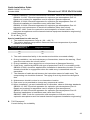
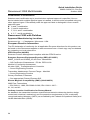
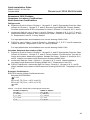
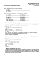
Quick Installation Guide 00825-0100-4716, Rev DA October 2009 Rosemount 3095 MultiVariable Rosemount 3095 MultiVariable™ Mass Flow Transmitter with HART® or FOUNDATION™ Fieldbus Protocol Rosemount 3095MF Series Flowmeter Transmitter P r oduc tDi s c ont i nue d Start Step 1: Mount the Transmitter Step 2: Transmitter Installation Step 3: Software Installation Step 4: Connect the Wiring and Power Up (HART or Fieldbus) Step 5: Configure the Transmitter (HART or Fieldbus) Step 6: Trim the Transmitter Product Certifications End www.rosemount.com ¢00825-0100-4716/¤ Quick Installation Guide 00825-0100-4716, Rev DA October 2009 Rosemount 3095 MultiVariable © 2009 Rosemount Inc. All rights reserved. All marks property of owner. Rosemount and the Rosemount logotype are registered trademarks of Rosemount Inc. Rosemount Inc. Emerson Process Management GmbH & Co. OHG 8200 Market Boulevard Chanhassen, MN USA 55317 T (US) (800) 999-9307, F (952) 949-7001 T (International) (952) 906-8888 Argelsrieder Feld 3 82234 Wessling Germany T 49 (8153) 9390, F49 (8153) 939172 Emerson Process Management Asia Pacific Private Limited Beijing Rosemount Far East Instrument Co., Limited 1 Pandan Crescent Singapore 128461 T (65) 6777 8211, F (65) 6777 0947 No. 6 North Street, Hepingli, Dong Cheng District Beijing 100013, China T (86) (10) 6428 2233, F (86) (10) 6422 8586 IMPORTANT NOTICE This installation guide provides basic guidelines for the Rosemount 3095 MultiVariable Mass Flow Transmitter (reference manual document number 00809-0100-4716). It also provides the basic electronics guidelines for the 3095MFA (reference manual document number 00809-0100-4809), the 3095MFC (reference manual document number 00809-0100-4810) and the 3095MFP (reference manual document number 00809-0100-4686). It does not provide instructions for configuration, diagnostics, maintenance, service, or troubleshooting. Refer to the appropriate reference manual for more instruction. These manuals are also available electronically on www.rosemount.com. WARNING Explosions could result in death or serious injury: Installation of this transmitter in an explosive environment must be in accordance with the appropriate local, national, and international standards, codes, and practices. • Before connecting a HART-based communicator in an explosive atmosphere, make sure the instruments in the loop are installed in accordance with intrinsically safe or non-incendive field wiring practices. • In an Explosion-Proof/Flame-Proof installation, do not remove the transmitter covers when power is applied to the unit. • Do not remove the transmitter covers in explosive environments when circuit is live. • Both transmitter covers must be fully engaged to meet explosion-proof requirements. Process leaks may cause harm or result in death. • To avoid process leaks, only use the o-ring designed to seal with the corresponding flange adapter. Electrical shock can result in death or serious injury. • Avoid contact with the leads and the terminals. High voltage that may be present on leads can cause electrical shock. 2 Quick Installation Guide 00825-0100-4716, Rev DA October 2009 Rosemount 3095 MultiVariable TRANSMITTER EXPLODED VIEW Certification Label Housing Terminal Block (HART) O-ring Electronics Board Cover Nameplate Module O-ring Sensor Module Housing Locking Screw RTD Connector Process Adapter O-ring Drain/Vent Valve Coplanar Flange Flange Adapter O-ring Optional Flange Adapters LCD Display Assembly Bolts LCD Display Cover Terminal Block (Fieldbus) 3 Quick Installation Guide 00825-0100-4716, Rev DA October 2009 Rosemount 3095 MultiVariable STEP 1: MOUNT THE TRANSMITTER Liquid Flow Applications 1. Place taps to the side of the line. 2. Mount beside or below the taps. 3. Mount the transmitter so that the drain/vent valves are oriented upward. Flow Gas Flow Applications 1. Place taps in the top or side of the line. 2. Mount beside or above the taps. Flow Flow Steam Flow Applications 1. Place taps to the side of the line. 2. Mount beside or below the taps. 3. Fill impulse lines with water. Flow Figure 1. Using a Mounting Bracket Panel Mount(1) (1) 4 Panel bolts are customer supplied. Pipe Mount Quick Installation Guide 00825-0100-4716, Rev DA October 2009 Rosemount 3095 MultiVariable STEP 2: TRANSMITTER INSTALLATION Consider Housing Rotation To improve field access or to better view the optional LCD display: 1. Loosen the housing rotation set screw. 2. Rotate the housing clockwise to the desired position – up to 180° from its original position. Over rotating will damage the transmitter. 3. If the desired position is attained, tighten the housing rotation set screw. 4. If the desired position cannot be reached because the housing will not rotate further, rotate the housing counterclockwise until in the desired position is attained (up to 180° from its original position). 5. Tighten the housing rotation set screw. Housing Rotation Set Screw (9/64-inch) Field Installation 1. Mount the transmitter a.Install the flange or flange/adapter bolt finger-tight. b.Torque bolts to initial torque value using a cross pattern (see Table 1). When installing to a mounting bracket, torque bolts to 125 in./lb (169 N/m) Table 1. Torque Cross Pattern Bolt Material Initial Value Final Value Carbon Steel (CS) Stainless Steel (SST) 300 in./lb (34 N/m) 150 in./lb (17 N/m) 650 in./lb (73 N/m) 300 in./lb (34 N/m) 2. Set the Security Jumper, which is located on the front of the electronics board inside the electronics housing cover. Putting the Security Jumper in the ON position will protect against configuration change from being unintentionally made. The transmitter operates normally if the jumpers are not installed. The Security default is OFF. 5 Quick Installation Guide Rosemount 3095 MultiVariable 00825-0100-4716, Rev DA October 2009 STEP 2 CONTINUED... 3. Set the Failure Mode Alarm (HART devices), which is located on the front of the electronics board inside the electronics housing cover. The Alarm Jumper position determines if the output is driven high or low when a failure is detected. The transmitter operates normally if the jumpers are not installed and the Alarm default fail is HI. Figure 2. Alarm Jumper Location Security Jumper Simulate Jumper HART Electronics Board FOUNDATION fieldbus Electronics Board 4. Set the Simulate Jumper (FOUNDATION fieldbus devices), which is located on the front of the electronics board inside the electronics housing cover. The jumper is used to simulate the measurement and is used as a lock-out feature for the AI function block. To enable the simulate feature, insert the jumper across ENABLE while the transmitter is powered. The default position for the Simulate Jumper is DISABLE. Enable the simulate feature after power is applied to the device. Simulate is automatically disabled regardless of jumper position if power is cycled. 5. Connect the transmitter to the process. 6. Install the RTD Cable Assembly (optional). All RTD 3095 Cable Assemblies use the 3095 RTD Cable Connector. Identify the cable type being installed and follow the steps below. • Installing an Armored Shielded RTD Cable (See Figure 3) a.Fully engage the black cable connector to the 3095 RTD connector. b.Tighten the cable adapter until metal contacts metal. c. Install the compression fitting. d.Tighten the cap onto the compression fitting. Figure 3. Armored Shielded RTD Cable Compression Fitting Conductive Bushing RTD Cap Cap Connect to RTD 3/4 to 1/2-14 NPT Adapter 6 Washer Black Cable Connector Cable Adapter Bushing Compression Fitting Quick Installation Guide 00825-0100-4716, Rev DA October 2009 Rosemount 3095 MultiVariable STEP 2 CONTINUED... • Installing a Shielded 3095 RTD Cable (See Figure 4) Note: Shielded cable is intended for use in a conduit. a.Fully engage the black cable connector to the 3095 RTD Connector. b.Tighten the cable adapter until metal contacts metal. Figure 4. Shielded RTD Cable Cable Adapter 1/2–14 NPT Black Cable Connector • Installing a ATEX/IECEx Flameproof 3095 RTD Cable (See Figure 5) a.Fully engage the black cable connector to the 3095 RTD Connector. b.Tighten the cable adapter and cable gland until metal contacts metal. Figure 5. ATEX/IECEx Flameproof RTD Cable RTD Cable Gland CM20 Cable Adapter Cable Gland Black Cable Connector/ RTD Connector 7. Check all process connections for leaks. 8. Connect the appropriate wiring (see Step 5). Ground the transmitter according to national and local electrical codes. Install field wiring grounding (optional). 7 Quick Installation Guide 00825-0100-4716, Rev DA October 2009 Rosemount 3095 MultiVariable STEP 2 CONTINUED... Bolting Considerations If the transmitter installation requires assembly of the process flanges, manifolds, or flange adapters, follow these assembly guidelines to ensure a tight seal for optimal performance characteristics of the transmitters. Use only bolts supplied with the transmitter or sold by Emerson as spare parts. Figure 6 illustrates common transmitter assemblies with the bolt length required for proper transmitter assembly. Figure 6. Common Transmitter Assemblies A. Transmitter with Coplanar Flange C. Transmitter with Traditional Flange and Optional Flange Adapters D. Transmitter with Coplanar Flange and Optional Manifold and Flange Adapters 4 x 2.25-in. (57 mm) 4 x 1.75-in. (44 mm) B. Transmitter with Coplanar Flange and Optional Flange Adapters 4 x 1.75-in. (44 mm) 4 x 1.50-in. (38 mm) 4 x 1.75-in. (44 mm) 4 x 2.88-in. (73 mm) Bolts are typically carbon steel or stainless steel. Confirm the material by viewing the markings on the head of the bolt and referencing Figure 7. If bolt material is not shown in Figure 7, contact the local Emerson Process Management representative for more information. Use the following bolt installation procedure: 1. Carbon steel bolts do not require lubrication and the stainless steel bolts are coated with a lubricant to ease installation. However, no additional lubricant should be applied when installing either type of bolt. 2. Finger-tighten the bolts. 3. Torque the bolts to the initial torque value using a crossing pattern. See Figure 7 for initial torque value. 4. Torque the bolts to the final torque value using the same crossing pattern. See Figure 7 for final torque value. 5. Verify that the flange bolts are protruding through the isolator plate before applying pressure. 8 Quick Installation Guide 00825-0100-4716, Rev DA October 2009 Rosemount 3095 MultiVariable STEP 2 CONTINUED... Figure 7. Torque values for the flange and flange adapter bolts Bolt Material Head Markings Initial Torque Final Torque Carbon Steel (CS) 300 in.-lbs. 650 in.-lbs. 150 in.-lbs. 300 in.-lbs. B7M Stainless Steel (SST) 316 B8M 316 R STM 316 316 SW 316 O-rings with Flange Adapters WARNING Failure to install proper flange adapter O-rings may cause process leaks, which can result in death or serious injury. The two flange adapters are distinguished by unique O-ring grooves. Only use the O-ring that is designed for its specific flange adapter, as shown below. Rosemount 3051S / 3051 / 2051 / 3095 Flange Adapter O-ring PTFE Based Elastomer Rosemount 1151 Flange Adapter O-ring PTFE Elastomer Whenever the flanges or adapters are removed, visually inspect the o-rings. Replace them if there are any signs of damage, such as nicks or cuts. If the o-rings are replaced, re-torque the flange bolts and alignment screws after installation to compensate for seating of the PTFE o-ring. 9 Quick Installation Guide Rosemount 3095 MultiVariable 00825-0100-4716, Rev DA October 2009 STEP 3: SOFTWARE INSTALLATION The 3095 Engineering Assistant (EA) for HART and 3095 Engineering Assistant (EA) for FOUNDATION Fieldbus software programs can be installed on the same computer. The applications cannot be open simultaneously. 3095 Engineering Assistant (EA) for HART Software Installation 1. Install the Program a.Place the CD-ROM in the drive and run setup.exe from Windows NT, 2000, or XP. b.After installing the software, install the HART Modem (see “Installing the HART Modem” on page 11). 2. Upgrade the previous versions of Engineering Assistant program (if required) a.Place the CD-ROM disk 2 into the drive and run the EAUpgrade.exe from Windows 98, NT, 2000, or XP. To properly install, the program will first uninstall Engineering Assistant from the computer. (Upgrades also are available at www.rosemount.com.) b.Remove the installation disk and reboot the computer to complete installation. c. To install the upgraded program, run the EAupgrade.exe from Windows 95,98, or NT again. 3. Connect the computer to the 3095 transmitter. a.Connect the HART modem cable to the computer using the 9-pin serial or USB communications port on the computer. b.Open the cover above the side marked Field Terminals, and connect the mini-grabbers to the two 3095 terminals marked COMM. 4. Select Engineering Assistant for HART from the program menu. On-Line Mode: EA communicates directly with the 3095 through AMS. a.In AMS Explorer view or AMS Connection view, right-mouse click on a 3095 device tag or icon. b.Select SNAP-ON/Linked Apps > Engineering Assistant. Off-Line Mode: Engineering Assistant does not communicate directly with the 3095. Instead, the EA configuration is sent to a 3095 later when Engineering Assistant is in on-line mode. In the off-line mode a future device needs to be created in order to launch Engineering Assistant. a.In AMS Explorer view or AMS Device Connection view, left click on Plant Database to the Area folder. b.Left click on Area to the Unit folder. c. Left click on Unit to the Equipment Module folder. d.Left click on Equipment Module to the Control Module folder. e.right-mouse click on Control Module to the pop-up context menu. f. Select Add Future Device. g.Select 3095MV Template and click OK. h.Right-mouse click on Future device to pop-up context menu. i. Select SNAP-ON/Linked Apps > Engineering Assistant. 10 Quick Installation Guide 00825-0100-4716, Rev DA October 2009 Rosemount 3095 MultiVariable STEP 3 CONTINUED... Installing the HART Modem After installing the 3095 Engineering Assistant, the HART modem configuration window automatically appears when the 3095 Engineering Assistant is opened. If this window is canceled, the HART modem may be installed manually with the following procedure. 1. Close AMS. From the Start Menu select Programs > 3095 Engineering Assistant > AMS Network. 2. Select Add from the AMS Network Configuration window. A “Select AMS Network Component Type” window will open. 3. Select Hart Modem. 4. Select Install. 5. Step through the Wizard. A prompt will inquire a COMM PORT. A typical default is “COMM 1”. 6. Select OK. Close out of the AMS Network Configuration window. 7. Re-open the HART Modem Properties. Click on the Connection tab and set the Retry Count to 5. Click the Advanced tab and check the Multidrop checkbox and set the Address Range as 0 to 2. 8. The configuration change will activate when 3095 Engineering Assistant is launched. NOTE Exit from the program if a Palm Pilot HotSync or any other program is shared with the COMM PORT. 3095 Engineering Assistant (EA) for FOUNDATION Fieldbus 1. Install the 3095 Engineering Assistant for FOUNDATION Fieldbus Program and the FOUNDATION fieldbus communication card drivers. a.Place CD-ROM disk 2 into the drive. b.Browse and select 3095 Engineering Assistant for FOUNDATION Fieldbus software application from Windows NT, 2000, or XP c. Open the ReadMe.txt file and follow the instructions provided. 2. Install the FOUNDATION Fieldbus communication card. a.Insert either the PCMCIA card or PCI card into the computer, following the instructions provided with the communications card. 3. Connect the 3095 transmitter to computer and establish communications. a.Connect the 9-pin communications cable into the FOUNDATION Fieldbus card port located in the computer. b.Connect communication wiring to connection ports labeled “D+” and “D-”. c. Open the transmitter cover on the side marked “Field Terminals” and connect the communication wires to the two 3095 transmitter terminals labeled “Fieldbus Wiring”. 4. Select the 3095 Engineering Assistant for FOUNDATION Fieldbus from the program menu or use the 3095 EA FOUNDATION fieldbus shortcut icon. 11 Quick Installation Guide 00825-0100-4716, Rev DA October 2009 Rosemount 3095 MultiVariable STEP 4: CONNECT WIRING AND POWER UP (HART) Use the following steps to wire the transmitter: 1. Remove the housing cover on the side marked FIELD TERMINALS. 2. Connect the signal leads to the terminals. NOTE Do not connect the powered signal wiring to the test terminals. Power could damage the test diode in the test connection. Shielded twisted pair cable should be used for best results. Use 24 AWG or larger wire and do not exceed 5,000 feet (1500 meters). 3. Plug and seal unused conduit connections. 4. Install wiring with a drip loop. Arrange the drip loop so the bottom is lower than the conduit connections and the transmitter housing. 5. Replace the housing cover. Figure 8 shows wiring connections necessary to power a 3095 and enable communications with a hand-held HART communicator. Figure 8. Transmitter Wiring Diagrams (4–20 man Power Supply) 24 Vdc Supply Current Meter RL 250 Installation of the transient protection terminal block does not provide transient protection unless the 3095 case is properly grounded. The dc power supply should provide power with less than two percent ripple. The total resistance load is the sum of the resistance of the signal leads and the load resistance of the controller, indicator, and related pieces. Note that the resistance of intrinsic safety barriers, if used, must be included. Figure 9. Load Limitation Load (Ohms) Max. Loop Resistance = Power Supply Voltage-11.0 0.022 2000 Operating Region 250 0 11.0 42.4(1) 16.5(2) Power Supply 55 (1) For CSA approval, power supply must not exceed 42.4 Vdc. (2) HART protocol communication requires a loop resistance value between 250-1100 ohms, inclusive. 12 Quick Installation Guide 00825-0100-4716, Rev DA October 2009 Rosemount 3095 MultiVariable STEP 4: CONNECT WIRING AND POWER UP (FIELDBUS) Use the following steps to wire the transmitter: 1. Remove the housing cover labeled “Field Terminals.” Terminals are not polarity sensitive. 2. Connect the signal leads to the terminals labeled “Fieldbus Wiring”. 3. Plug and seal unused conduit connections. 4. Install wiring with a drip loop. Arrange the drip loop so the bottom is lower than the conduit connections and the transmitter housing. 5. Replace the housing cover. NOTE Do not attach shield to ground. Power Supply To operate and provide complete functionality, the transmitter requires the supply voltage to be within the ranges shown below. Approval Option Code B, D, F, J, K, L, N, 2, 4, 9 A, C, E, G, H, P, R, 0, 3, 5, 7, 8 T, U, V, W, Y, 6 Supply Voltage 9-30 Vdc 9-32 Vdc 9-17.5 Vdc Power Conditioner A fieldbus segment requires a power conditioner to isolate the power supply filter and decouple the segment from other segments attached to the same power supply. Grounding Signal wiring of the fieldbus segment can not be grounded. Grounding out one of the signal wires will shut down the entire fieldbus segment. Shield Wire Ground To protect the fieldbus segment from noise, grounding techniques for shield wire usually requires one and only one grounding point for shield wire to avoid creating a ground loop. The ground point is typically at the power supply. Signal Termination For every fieldbus segment a terminator should be installed at the beginning and at the end of each segment. 13 Quick Installation Guide 00825-0100-4716, Rev DA October 2009 Rosemount 3095 MultiVariable STEP 5: CONFIGURE THE TRANSMITTER (HART) Setting the Loop to Manual Set the process application loop to manual when preparing to send or request data that would disrupt the loop or change the output of the transmitter. A prompt will appear reminding the user to set the loop to manual when necessary. Acknowledging this prompter does not set the loop to manual. Send the Configuration to the Transmitter Use the following steps to send the configuration to the transmitter. All previous transmitter information will be overwritten when the information is sent. 1. EA: Select Configure > Configure Flow. 2. Step through the Flow Configuration wizard. 3. Check Send Flow Configuration to update the transmitter’s flow calculation. 4. From the Device Connection window, right click on the transmitter icon, and select Configuration Properties. On the Basic Setup window, verify the units of measure and the LRV to URV range (4-20 mA setpoints). Basic Configuration Parameters NOTE: A check (✓) indicates the basic configuration parameters. At minimum, these parameters should be verified as part of the configuration and startup procedure. Transmitters are shipped from Emerson Process Management fully calibrated and configured for the application when C2 Option is ordered. Without C2 Option, configuration will be by the factory default. Table 2. HART Communicator Fast Key Sequence Function/Variable % rnge % rnge 4V is AO Alrm typ AO1 AO1 AP Damping AP Sens Trim AP Units Absolute (AP) Atm Press Cnfg Burst mode Burst option Change PV Assgn Change SV Assgn Change TV Assgn Change 4V Assgn D/A trim DP Low Flow Cutoff DP LRV 14 Fast Key Sequence 1, 1, 2 1, 1, 5, 1, 3 1, 1, 5, 4, 1 1, 4, 1, 1, 1 1, 1, 3 3 1, 4, 2, 5, 2 1, 2, 2, 1, 2 1, 3, 2, 2 1, 1, 4, 2 1, 4, 2, 3 1, 4, 1, 2, 4, 2 1, 4, 1, 2, 4, 1 1, 1, 5, 1, 5 1, 1, 5, 2, 3 1, 1, 5, 3, 3 1, 1, 5, 4, 3 1, 2, 2, 2, 1 1, 4, 6 4 Quick Installation Guide 00825-0100-4716, Rev DA October 2009 ✓ ✓ ✓ ✓ Rosemount 3095 MultiVariable Function/Variable Fast Key Sequence DP Sens Trim DP Snsr Range DP URV DP units Date Descriptor Diff pres damp Diff pres Diff pres Fld dev rev Flo rate Flow Rate Special Units Flow Units GP Damping GP Sens Trim GP Units Gage (GP) Hardware rev LCD Settings Loop test Message Num req preams Num resp preams PV is Poll addr Process temp unit Process temp RS type RTD Config Range values Reset SP Snsr Range SP Type SV is Scaled D/A trim Status group 1 Totalizer Totalizer Special Units TV is Tag Temp Sens Trim Temp damp Universal rev View status Write protect Xmtr Var Slot Assn 1, 2, 2, 1, 1 1, 3, 5, 1 5 1, 3, 2, 1 1, 3, 4, 4 1, 3, 4, 2 1, 4, 2, 4 1, 1, 1 2 1, 3, 4, 9, 2 1, 1, 4, 5 1, 4, 5, 1 1, 3, 2, 5 1, 4, 2, 5, 4 1, 2, 2, 1, 3 1, 3, 2, 4 1, 1, 4, 4 1, 3, 4, 9, 4 1, 4, 3 1, 2, 1, 1 1, 3, 4, 3 1, 4, 1, 2, 2 1, 4, 1, 2, 3 1, 1, 5, 1, 1 1, 4, 1, 2, 1 1, 3, 2, 3 1, 1, 4, 3 1, 3, 5, 10 1, 4, 2, 2 1, 3, 3 1, 2, 1, 3 1, 3, 5, 2 1, 3, 5, 3 1, 1, 5, 2, 1 1, 2, 2, 2, 2 1, 6 1, 4, 4 1, 4, 5, 2 1, 1, 5, 3, 1 1, 3, 1 1, 2, 2, 1, 4 1, 4, 2, 5, 3 1, 3, 4, 9, 1 1, 2, 1, 2 1, 3, 4, 8 1, 4, 1, 2, 4, 3 15 Quick Installation Guide 00825-0100-4716, Rev DA October 2009 Rosemount 3095 MultiVariable STEP 5: CONFIGURE THE TRANSMITTER (FIELDBUS) Each FOUNDATION fieldbus host or configuration tool has a different way of displaying and performing configurations. Some use Device Descriptions (DD) or DD methods for configuration and to display data consistently across platforms. There is no requirement that a host or configuration tool support these features. Use the following block examples to do basic configuration to the transmitter. For more advanced configurations including configuring the 3095 Mass Flow transducer block, see the 3095 Manual (00809-0100-4716). NOTE DeltaV users should use DeltaV Explorer for the Resource and Transducer blocks and Control Studio for the Function Blocks. Send the Configuration to the Transmitter Use the following steps to create and send the mass flow configuration to the Mass Flow Transducer Block. NOTE All previous Mass Flow transducer block information will be overwritten when the configuration is sent. 1. Open the 3095 Engineering Assistant for FOUNDATION fieldbus. 2. Select scan to scan the FOUNDATION fieldbus segment and select the device requiring the new or updated mass flow configuration file. 3. Select the EA Wizard. 4. Step through the Flow Configuration Wizard to create a mass flow configuration file. 5. Save the new or updated mass flow configuration file. Files must be saved for future review or update. Files cannot be uploaded from the Mass Flow Transducer Block. 6. Select send to send the mass flow configuration file to the selected transmitter Mass Flow Transducer Block. To configure the AI Block AI Block configuration parameters Parameters Enter Data Channel 1 = Pressure 2 = Static Pressure 3 = Process Temperature 4 = Device Temperature 5 = Mass Flow L_Type Direct, Indirect, or Square Root XD_Scale Scale and Engineering Units (Note: Only select the units that are supported by the device.) Pressure: Pa bar inH20 @ 68°F kPa mbar mmH20 @ 68°F mPa atm ftH20 @ 68°F Temperature: °C °F Out_Scale 16 psi g/cm2 kg/cm2 torr K Mass Flow Rate: lbm/sec lbm/min lbm/hr kg/min kg/hour g/sec StdCuFt/sec StdCuFt/min StdCuFt/hr StdCuFt/day StdCuM/min StdCuM/hr Scale and Engineering Units lbm/day g/min kg/sec g/hr StdCuM/sec StdCuM/day inHg @ 0°C mmHg @ 0°C mmH20 @ 4°C inH20 @ 4°C Quick Installation Guide 00825-0100-4716, Rev DA October 2009 Rosemount 3095 MultiVariable STEP 6: TRIM THE TRANSMITTER NOTE Transmitters are shipped from Emerson Process Management fully calibrated and configured for the application when C2 Option is ordered. Without C2 Option, configuration will be by the factory default (span = upper range limit for FOUNDATION fieldbus transmitters). Zero Trim A zero trim is a single-point adjustment used for compensating mounting position effects and line pressure effects. When performing a zero trim, ensure the low side block valve is closed, the equalize valve is open, the high side block valve is open, and all wet legs are filled to the correct level. Using the Field Communicator 1. Equalize the transmitter and connect Field communicator. 2. At the menu, input the Fast Key sequence. 3. Follow the commands to perform a zero trim. Fast Keys 1, 2, 2, 1, 1 1, 2, 2, 1, 2 Steps Trim DP Offset (Zero) Trim SP Offset (Zero), (AP, GP) 4. Once the zero trim is complete, verify that the high side block valve is open, close the equalize valve tightly, then open the low side block valve. Using the Foundation Fieldbus AI Block For zero errors greater than the allowable zero trim, compensate for the offset by using the XD_Scaling, Out_Scaling and Indirect L_Type. Using the Foundation Fieldbus Host System Perform a Zero Trim method if the host system supports methods associated with the TRANSDUCER 1400 block. Otherwise, if the host system does not support methods see the 3095 Manual (00809-0100-4716). NOTE For Absolute Pressure (AP) Sensor: If open to atmosphere, reading should be at atmospheric pressure (roughly 12 - 15 psi (0.8 - 1.0 bar), not zero. Use a barometer that is four times as accurate as the 3095 AP sensor. 17 Quick Installation Guide Rosemount 3095 MultiVariable 00825-0100-4716, Rev DA October 2009 PRODUCT CERTIFICATIONS Rosemount 3095 with HART Approved Manufacturing Locations Rosemount Inc. — Chanhassen, Minnesota USA Emerson Process Management GmbH & Co. — Wessling, Germany Emerson Process Management Asia Pacific Private Limited — Singapore Beijing Rosemount Far East Instrument Co., Limited – Beijing, China European Directive Information The EC declaration of conformity for all applicable European directives for this product can be found on the Rosemount website at www.rosemount.com. A hard copy may be obtained by contacting our local sales office. ATEX Directive (94/9/EC) Emerson Process Management complies with the ATEX Directive. European Pressure Equipment Directive (PED) (97/23/EC) 3095F_2/3,4/D and 3095M_2/3,4/D Flow Transmitters — QS Certificate of Assessment - EC No. PED-H-100 Module H Conformity Assessment All other 3095_ Transmitters/Level Controller — Sound Engineering Practice Transmitter Attachments: Process Flange - Manifold — Sound Engineering Practice Electro Magnetic Compatibility (EMC) (2004/108/EC) 3095 Flow Transmitters — EN 61326-1:1997 – A1, A2, and A3 Ordinary Location Certification for Factory Mutual As standard, the transmitter has been examined and tested to determine that the design meets basic electrical, mechanical, and fire protection requirements by FM, a nationally recognized testing laboratory (NRTL) as accredited by the Federal Occupational Safety and Health Administration (OSHA). Rosemount 3095 HART Hazardous Locations Certifications North American Certifications FM Approvals A Explosion Proof for Class I, Division 1, Groups B, C, and D. Dust-Ignition Proof for Class II/Class III, Division 1, Groups E, F, and G. Enclosure Type 4X. Factory Sealed. Provides nonincendive RTD connections for Class I, Division 2, Groups A, B, C, and D. J Intrinsically Safe for use in Class I, II and III, Division 1, Groups A, B, C, D, E, F, and G hazardous outdoor locations. Non-incendive for Class I, Division 2, Groups A, B, C, and D. Temperature Code T4. Factory Sealed. For input parameters and installation see control drawing 03095-1020. 18 Quick Installation Guide 00825-0100-4716, Rev DA October 2009 Rosemount 3095 MultiVariable Canadian Standards Association (CSA) C Explosion Proof for Class I, Division 1, Groups B, C, and D. Dust-Ignition Proof for Class II/Class III, Division 1, Groups E, F, and G. CSA enclosure Type 4X suitable for indoor and outdoor hazardous locations. Provides nonincendive RTD connection for Class I, Division 2, Groups A, B, C, and D.Factory Sealed. Install in accordance with Rosemount Drawing 03095-1024. Approved for Class I, Division 2, Groups A, B, C, and D. K Intrinsically Safe for Class I, Division 1, Groups A, B, C, and D. when installed in accordance with Rosemount drawing 03095-1021. Temperature Code T3C. For input parameters and installation see control drawing 03095-1021. European Certifications F ATEX Intrinsic Safety Certificate Number: BAS98ATEX1359X Ex ia IIC T5 (Tamb = –45 °C to 40 °C) Ex ia IIC T4 (Tamb = –45 °C to 70 °C) 1180 II 1 G Table 3. Connection Parameters (Power/Signal Terminals) Ui = 30V Ii = 200 mA Pi = 1.0 W Ci = 0.012 µF Li = 0 Table 4. Temperature Sensor Connection Parameters Uo = 30V Io = 19 mA Po = 140 mW Ci = 0.002 µF Li = 0 Table 5. Connection Parameters for Temperature Sensor Terminals Gas Group IIC Co = 0.066 F Co = 0.560 F Gas Group IIB Co = 1.82 F Gas Group IIA Lo = 96 mH Gas Group IIC Lo = 365 mH Gas Group IIB Lo = 696 mH Gas Group IIA Lo/Ro = 247 H/ohm Gas Group IIC Lo/Ro = 633 H/ohm Gas Group IIB Lo/Ro= 633 H/ohm Gas Group IIA Special Conditions for Safe Use The 3095, when fitted with the transient terminal block (order code B), are not capable of withstanding the 500 volts insulation test required by EN 60079-11, Clause 6.3.12. This condition must be accounted for during installation. 19 Quick Installation Guide 00825-0100-4716, Rev DA October 2009 Rosemount 3095 MultiVariable G H P ATEX Type n Certificate Number: BAS98ATEX3360X Ex nL IIC T5 (Tamb = –45 °C to 40 °C) Ex nL IIC T4 (Tamb = –45 °C to 70 °C) Ui = 55V The apparatus is designed for connection to a remote temperature sensor such as a resistance temperature detection (RTD) Special Conditions for Safe Use The 3095, when fitted with the transient terminal block (order code B), are not capable of withstanding the 500 volts insulation test required by EN60079-15 Clause 6.8.1. This condition must be accounted for during installation. ATEX Flameproof Certificate Number: KEMA02ATEX2320X II 1/2 G Ex d IIC T5 (-50°C Tamb 80°C) T6 (-50°C Tamb 65°C) 1180 Special Conditions for Safe Use (x): The device contains a thin wall diaphragm. Installation, maintenance, and use shall take into account the environmental conditions to which the diaphragm will be subjected. The manufacturer’s instructions for installation and maintenance shall be followed in detail to assure safety during its expected lifetime. ATEX Dust Certificate Number: KEMA02ATEX2321 II 1 D Ex tD A20 T 90°C(-40°C Tamb 80°C) V = 55 Vdc MAX I = 23 mA MAX IP66 1180 IECEx Certifications (HART) 4 IECEx Intrinsic Safety Certificate Number: IECEx BAS06.0070X Ex ia IIC T4 (-45°C Ta 70°C) Ex ia IIC T5 (-45°C Ta 40°C) Table 6. Input Parameters HART I.S. Ui = 30Vdc Ii = 200 mAdc Pi = 1.0 W Ci = 12 nF Li = 0 20 II 3 G Quick Installation Guide 00825-0100-4716, Rev DA October 2009 Rosemount 3095 MultiVariable Table 7. RTD Terminals Entity Parameters Uo = 30Vdc Io = 19 mAdc Po = 140 mW The capacitance and either the Inductance or the Inductance to Resistance Ratio (L/R) of the load connected to the 4-pin connector must not exceed the following values: Group Capacitance (F) Inductance (mH) IIC IIB IIA 0.066 0.56 1.82 96 365 696 or L/R Ratio H/Ohm 247 633 633 NOTE 1. The external circuit contains no combined lumped inductance and capacitance greater than 1% of the above values. Or 2. The inductance and capacitance are distributed as in a cable. Or 3. The external circuit contains only lumped inductance or only lumped capacitance in combination with a cable. In all other situations e.g. combined lumped inductance and capacitance, up to 50% of each of L and C values is allowed. 5 7 8 Conditions of Certification (X): When fitted with the transient option, the apparatus is not capable of withstanding the 500V electrical strength test as defined in Clause 6.3.12 of IEC 60079-11. This must be taken into account during installation. IECEx Type n Certificate Number: IECEx BAS06.0071X Ex nA nL IIC T4 (-45°C Ta 70°C) Ex nA nL IIC T5 (-45°C Ta 40°C) Ui = 55V dc max Conditions of Certification (X): When fitted with the transient option, the apparatus is not capable of withstanding the 500V electrical strength test as defined in Clause 6.8.1 of IEC 60079-15. This must be taken into account during installation. IECEx Flameproof Certificate Number: IECEx KEM 06.0018 Zone 0/1 Ex d IIC T6 (-20°C Ta 65°C) Zone 0/1 Ex d IIC T5 (-20°C Ta 80°C) Vmax = 55 Vdc Imax = 23 mAdc IECEx Dust Certificate Number: IECEx KEM 06.0018 Ex tD A22 T90°C IP66 INMETRO Certifications E INMETRO Flameproof BR-Ex d IIC T6/T5 21 Quick Installation Guide Rosemount 3095 MultiVariable 00825-0100-4716, Rev DA October 2009 China (NEPSI) Certifications 2 China Intrinsic Safety Ex ia IIC T4 Special conditions for safe use (x): 1. 3095 Series transmitter with temperature sensor have not been certified. 2. The temperature of process medium should be less than 121 °C. 3. The ambient temperature range is (-40~+60) °C. 4. Safety parameters 4.1 Input parameters 4.1.1 Transmitter with output code “V” Ui = 30V__ Ii = 300 mA __Pi = 1.3W__ C i 0 __ L i 0 4.1.2 Other transmitters Ui=40V _Ii=165 mA__Pi=1.0W _Ci=0.012 F _Li=20 H 4.2 RTD terminals Uo=30V_Io=12 mA _Po=100 mW _Co=66nF _Lo=100 mH 5. The cable entry of transmitter should be protected to ensure the degree of protection of the enclosure IP 20 (GB4208-1993) at least. 6. The terminals for connection to power supply of transmitter should be connected to associated apparatus certified by NEPSI in accordance with GB3836.1-2000 and GB3836.4-2000 to establish intrinsic safety system, it has to fulfill the following requirements: UoUi __IoIi __PoPi __CoCc+Ci __LoLc+Li Note: Cc, Lc the distributed capacitance and inductance of the cables Uo, Io, Po maximum output parameters of associated apparatus Co, Lo, maximum external parameters of associated apparatus 7. The terminals for connection to sensor of transmitter should be connected to intrinsic safety sensor certified by NEPSI in accordance with GB3836.1-2000 and GB3836.4-2000 to establish intrinsic safety system, it has to fulfill the following requirements: Ui Uo __Ii Io __Pi Po __Ci Co-Cc __Li Lc+Lo Note: Cc, Lc the distributed capacitance and inductance of the cables Ui, Ii, Pi maximum input parameters of intrinsic safety sensor Ci, Li, maximum internal parameters of intrinsic safety sensor 8. The cables between the transmitter, associated apparatus and sensor are 2-core shielded cables (the cables must have insulated shield). The cable core section area should be more than 0.5 mm2. The shielded has to be grounded in non-hazardous area and isolated from the housing. The wiring has to not be affected by electromagnetic disturbance. 9. Associated apparatus should installed in a safe location, and during installation, operation and maintenance, the regulations of the instruction manual have to be strictly observed. 10.End users is not permitted to change any components insides. 22 Quick Installation Guide 00825-0100-4716, Rev DA October 2009 Rosemount 3095 MultiVariable 11.When installation, use and maintenance transmitter, observe the following standards GB3836.13-1997 “Electrical apparatus for explosive gas atmospheres Part 13: Repair and overhaul for apparatus used in explosive gas atmospheres” GB3836.15-2000 “Electrical apparatus for explosive gas atmospheres Part 15: Electrical installations in hazardous area (other than mines)” GB3836.16-2006 “Electrical apparatus for explosive gas atmospheres Part 16: Inspection and maintenance of electrical installation (other than mines): GB50257-1996 “Code for construction and acceptance of electric device for explosion atmospheres and fire hazard electrical equipment installation engineering” 3 China Flameproof Ex d II B+H2T4~T6 Special conditions for safe use (x): 1. The ambient temperature range is (-20 ~ +60) °C. 2. The relation between temperature class and maximum temperature of process medium is as following. Maximum Temperature of Process Medium (°C) Temperature Class 121 95 80 T4 T5 T6 3. The earth connection facility in the enclosure should be connected reliably. 4. During installation, use and maintenance of transmitter, observe the warning, “Don’t open the cover when the circuit is alive.” 5. During installation, there should be no mixture harm to flameproof housing. 6. Cable entry, certified by NEPSI with type of protection Ex d IIC in accordance with GB3836.2-2000, should be applied when installation in hazardous location. Five full threads should be in engagement when the cable entry is assembled onto the transmitter. 7. The diameter of cable should observe the instruction manual of cable entry. The compressing nut should be fastened. The aging of seal ring should be changed in time. 8. Maintenance should be done in non-hazardous location. 9. End users is not permitted to change any components insides. 10. When installation, use and maintenance of transmitter, observe following standards. GB3836.13-1997 “Electrical apparatus for explosive gas atmospheres Part 13: Repair and overhaul for apparatus used in explosive gas atmospheres” GB3836.15-2000 “Electrical apparatus for explosive gas atmospheres Part 15: Electrical installations in hazardous area (other than mines)” GB50257-1996 “Code for construction and acceptance of electric device for explosion atmospheres and fire hazard electrical equipment installation engineering” R TIIS Flameproof Consult factory for availability 23 Quick Installation Guide Rosemount 3095 MultiVariable 00825-0100-4716, Rev DA October 2009 Combinations of Certifications Stainless steel certification tag is provided when optional approval is specified. Once a device labeled with multiple approval types is installed, it should not be reinstalled using any other approval types. Permanently mark the approval label to distinguish it from unused approval types. B D L 9 A and J combination C and K combination F, G, H, and P combination 4, 5, 7, and 8 combination Rosemount 3095 with Fieldbus Approved Manufacturing Locations Rosemount Inc. — Chanhassen, Minnesota USA European Directive Information The EC declaration of conformity for all applicable European directives for this product can be found on the Rosemount website at www.rosemount.com. A hard copy may be obtained by contacting our local sales office. ATEX Directive (94/9/EC) Emerson Process Management complies with the ATEX Directive. European Pressure Equipment Directive (PED) (97/23/EC) 3095F_2/3,4/D and 3095M_2/3,4/D Flow Transmitters — QS Certificate of Assessment - EC No. PED-H-100 Module H Conformity Assessment All other 3095_ Transmitters/Level Controller — Sound Engineering Practice Transmitter Attachments: Process Flange - Manifold — Sound Engineering Practice Primary Elements, Flowmeter — See appropriate Primary Element QIG Electro Magnetic Compatibility (EMC) (2004/108/EC) 3095 Flow Transmitters — EN 50081-1: 1992; EN 50082-2:1995; EN 61326-1:1997 – A1, A2, and A3 Ordinary Location Certification for Factory Mutual As standard, the transmitter has been examined and tested to determine that the design meets basic electrical, mechanical, and fire protection requirements by FM, a nationally recognized testing laboratory (NRTL) as accredited by the Federal Occupational Safety and Health Administration (OSHA). 24 Quick Installation Guide 00825-0100-4716, Rev DA October 2009 Rosemount 3095 MultiVariable Rosemount 3095 Fieldbus Hazardous Locations Certifications North American Certifications FM Approvals A J V Explosion Proof for Class I, Division 1, Groups B, C, and D. Dust-Ignition Proof for Class II/Class III, Division 1, Groups E, F, and G. Enclosure type NEMA 4X. Factory Sealed. Provides nonincendive RTD connections for Class I, Division 2, Groups A, B, C, and D. Intrinsically Safe for use in Class I, II and III, Division 1, Groups A, B, C, D, E, F, and G hazardous outdoor locations. Non-incendive for Class I, Division 2, Groups A, B, C, and D. Temperature Code T4. Factory Sealed. For input parameters and installation see control drawing 03095-1020. FISCO for use in Class I, II and III, Division 1, Groups A, B, C, D, E, F, and G hazardous outdoor locations. Temperature Code T4. Factory Sealed. For input parameters and installation see control drawing 03095-1020. Canadian Standards Association (CSA) C Explosion Proof for Class I, Division 1, Groups B, C, and D. Dust-Ignition Proof for Class II/Class III, Division 1, Groups E, F, and G. Factory Sealed. CSA enclosure Type 4X for indoor and outdoor hazardous locations. Suitable for Class I, Division 2, Groups A, B, C, and D. Install in accordance with Rosemount Drawing 03095-1024. K Intrinsically Safe for Class I, Division 1, Groups A, B, C, and D. When installed in accordance with Rosemount Drawing 03095-1021. Temperature Code T3C. W FISCO Field Device. Intrinsically Safe for Class I, Division 1, Groups A, B, C, and D. When installed in accordance with Rosemount Drawing 03095-1021. Temperature Code T3C. European Certifications F/T ATEX Intrinsic Safety Certificate Number: Baseefa 05ATEX0022X II 1 G EEx ia IIC T5 (Tamb = -45°C to 40°C) EEx ia IIC T4 (Tamb = -45°C to 70°C) 1180 Table 8. Connection Parameters (Power/Signal Terminals) Fieldbus (F Option) Ui = 30V Ii = 300 mA Pi = 1.3 W Ci = 3.3 nF Li = 0 FISCO (T Option) Ui = 17.5V Ii = 380 mA Pi = 5.32 W Ci < 5 nF Li = 10 µH 25 Quick Installation Guide Rosemount 3095 MultiVariable 00825-0100-4716, Rev DA October 2009 Table 9. Temperature Sensor Connection Parameters Uo = 30V Io = 19 mA Po = 140 mW Table 10. Connection Parameters for Temperature Sensor Terminals Co = 0.066 F Gas Group IIC Co = 0.560 F Gas Group IIB Co = 1.82 F Gas Group IIA Lo = 96 mH Gas Group IIC Lo = 365 mH Gas Group IIB Lo = 696 mH Gas Group IIA Lo/Ro = 247 H/ohm Gas Group IIC Lo/Ro = 633 H/ohm Gas Group IIB Lo/Ro= 633 H/ohm Gas Group IIA G H Special conditions for safe use (x): Versions of the apparatus fitted with the transient protected terminals are not capable of withstanding the 500 volts insulation test required by Clause 6.4.12 of EN 50020:2002. This must be taken into account when installing the apparatus. ATEX Type N Certificate Number: Baseefa05ATEX0023X II 3 G EEx nA nL IIC T5 (Tamb = –45 °C to 40 °C) EEx nA nL IIC T4 (Tamb = –45 °C to 70 °C) Ui = 55V RTD Terminals - The apparatus is designed for connection to a remote temperature sensor such as a resistance temperature detection (RTD). Special Conditions for Safe Use Versions of the apparatus fitted with the transient protected terminals are not capable of withstanding the 500 volts insulation test required by Clause 8.1 of EN 60079-15:2003. This must be taken into account when installing the apparatus. ATEX Flameproof Certificate Number: KEMA02ATEX2320X II 1/2 G EEx d IIC T5 (-50°C Tamb 80°C) T6 (-50°C Tamb 65°C) Vmax = 55 Vdc MAX Imax = 23 mA MAX IP66 1180 Special conditions for safe use (x): The device contains a thin wall diaphragm. Installation, maintenance, and use shall take into account the environmental conditions to which the diaphragm will be subjected. The manufacturer’s instructions for installation and maintenance shall be followed in detail to assure safety during its expected lifetime. 26 Quick Installation Guide 00825-0100-4716, Rev DA October 2009 P Rosemount 3095 MultiVariable ATEX Dust Certificate Number: KEMA02ATEX2321 II 1 D T90°C (-50°C Tamb 80°C) Vmax = 55 Vdc Imax = 23 mA IP66 1180 IECEx Certifications (Fieldbus) 4/Y IECEx Intrinsic Safety Certificate Number: IECEx BAS05.0023X Ex ia IIC T4 (-45°C Ta 70°C) Ex ia IIC T5 (-45°C Ta 40°C) Table 11. Input Parameters Fieldbus I.S. Ui = 30Vdc Ii = 300 mAdc Pi = 1.3 W Ci = 3.3 nF Li = 0 FISCO Ui = 17.5Vdc Ii = 380 mAdc Pi = 5.32 W Ci 5 nF Li 10 mH Table 12. RTD Terminals Entity Parameters Uo = 30Vdc Io = 19 mAdc Po = 140 mW The capacitance and either the Inductance or the Inductance to Resistance Ratio (L/R) of the load connected to the 4-pin connector must not exceed the following values: Group IIC IIB IIA 5 Capacitance (F) 0.066 0.56 1.82 Inductance (mH) 96 365 696 or L/R Ratio H/Ohm 247 633 633 Conditions of Certification (X): When fitted with the transient option, the apparatus is not capable of withstanding the 500V electrical strength test as defined in Clause 6.4.12 of IEC 60079-11: 1999. This must be taken into account during installation. IECEx Type n Certificate Number: IECEx BAS05.0024X Ex nC IIC T4 (-45°C Ta 70°C) Ex nC IIC T5 (-45°C Ta 40°C) Ui = 55V dc max Conditions of Certification (X): When fitted with the transient option, the apparatus is not capable of withstanding the 500V electrical strength test as defined in Clause 8 of IEC 60079-15: 1987. This must be taken into account during installation. 27 Quick Installation Guide Rosemount 3095 MultiVariable 7 8 00825-0100-4716, Rev DA October 2009 IECEx Flameproof Certificate Number: IECEx KEM 06.0018 Zone 0/1 Ex d IIC T6 (-20°C Ta 65°C) Zone 0/1 Ex d IIC T5 (-20°C Ta 80°C) Vmax = 55 Vdc Imax = 23 mAdc IECEx Dust Certificate Number: IECEx KEM 06.0018 Ex tD A22 T90°C IP66 Combinations of Certifications Stainless steel certification tag is provided when optional approval is specified. Once a device labeled with multiple approval types is installed, it should not be reinstalled using any other approval types. Permanently mark the approval label to distinguish it from unused approval types. B D L 6 9 28 A and J combination C and K combination F, G, H, and P combination T, G, H, and P combination 4, 5, 7, and 8 combination Quick Installation Guide 00825-0100-4716, Rev DA October 2009 Rosemount 3095 MultiVariable 29 Quick Installation Guide Rosemount 3095 MultiVariable 30 00825-0100-4716, Rev DA October 2009 Quick Installation Guide 00825-0100-4716, Rev DA October 2009 Rosemount 3095 MultiVariable 31 Quick Installation Guide Rosemount 3095 MultiVariable 32 00825-0100-4716, Rev DA October 2009