1
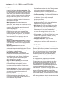
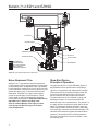
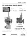
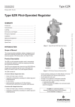
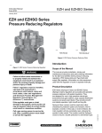
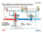
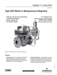
Bulletin 71.2:EZH and EZHSO
April 2014
EZH and EZHSO Series Pressure
Reducing Regulators
W8480
Figure 1. Type EZH Pressure Reducing Regulator
• 1500 psig / 103 bar Inlet / Outlet Rating
• No Atmospheric Bleed
• Common Body Platform
• Integral Slam Shut Configurations Available
• Bubble-Tight Shutoff
• Full Usable Capacity
• In-Line Maintenance
• Precise Pressure Control
• Long Life in Severe Service Applications
• High Turn Down Capability
• NPS 1 through 4 / DN 25 through
100 Body Sizes Available
• Optional Whisper Trim™ Cage Noise
Abatement (Up to 8 dBA)
• Integral Slam Shut for Overpressure
and Underpressure Protection
D103081X012
• Spring-to-Close and Spring-to-Open Versions
www.fisherregulators.com
Bulletin 71.2:EZH and EZHSO
Features
• Long Life in Severe Service Applications—The
EZH and EZHSO Series utilize a metal plug design
to deflect particles and debris away from the softseat, which gives enhanced resistance to particle
erosion to provide a longer service life. In addition,
the EZH and EZHSO Series can be constructed
with Fluorocarbon (FKM) soft parts to extend
service life in applications where liquid aromatics
are entrained in the gas.
• Main Diaphragm—The main diaphragm is
Nitrile (NBR) reinforced with fabric and coated
with a PVC, which protects and extends the service
life of the regulator in applications where the liquids
commonly found in natural gas pipelines tend to
shorten diaphragm life.
• Common Body Platform—The EZH and
EZHSO Series use the same standard Fisher®
E-Body which is also used in Type EZR pressure
reducing regulator and Types EZ, ES, ED and ET
pressure reducing control valves. This will allow
easy conversion from one product to another
without the need to remove the E-Body from
the pipeline.
• Spring-to-Close and Spring-to-Open Versions—
Optional positions to choose from in case of main
valve diaphragm failure or lack of supply pressure
to the pilot.
• Bubble-Tight Shutoff—The EZH and
EZHSO Series have knife-edged, metal plug and a
soft seat which provide bubble tight shutoff for use
in applications where positive shutoff is required.
For example: dead-end systems.
• No Atmospheric Bleed—The EZH and
EZHSO Series eliminate nuisance and wasteful
bleed gas to atmosphere by utilizing a pilotoperated two-path control system, which bleeds
100% of the gas to the downstream system
while the regulator is operating.
• High Turn Down Capability—The oversized
diaphragm and unique piloting system of the
EZH and EZHSO Series allow for high turn
down, which will provide superior pressure control
in systems with large variations in downstream
flow demand.
• In-Line Maintenance—Top entry design provides
easier maintenance. Trim parts can be inspected,
cleaned and replaced without removing the
body from pipeline.
• Noise Abatement Trim—The EZH and
EZHSO Series offer an optional Whisper Trim™
Cage which is integral to the regulator. Allows for a
noise attenuation of up to 8 dBA.
2
• Precise Pressure Control—The EZH and
EZHSO Series use the PRX Series and Type SA/2
pilot system to provide stable and accurate
downstream pressure control regardless of load
changes or inlet pressure variations.
• Full Pressure Rating—The EZH and EZHSO Series
have equal inlet and outlet pressure rating
of 1500 psig / 103 bar, which allows easier
selection and requires no special startup or
shutdown procedures.
• Full Usable Capacity—Fisher brand regulators
are laboratory tested. 100% of the published flow
capacity can be used with confidence.
• Disk Design—The EZH and EZHSO Series offer
disks for the main body made from Nitrile (NBR),
Fluorocarbon (FKM) and Polyurethane (PU).
Polyurethane (PU) provides better abrasion
resistance properties and a high durometer rating
to extend the working life of the disk in difficult
applications where disk erosion is an issue.
• O-ring Design—The EZH and EZHSO Series use
elastomer O-rings instead of gaskets, reducing
maintenance and assembly time.
• Slam-Shut Protection—Types EZHOSX
and EZHSO-OSX discontinue gas service by
shutting the gas off if there is an overpressure or
underpressure condition.
Introduction
Types EZH (Spring-to-Close version) and EZHSO
(Spring-to-Open version) regulators are accurate pilotoperated, pressure-balanced, soft-seated regulators.
They are designed for use in high pressure natural
gas transmission, city gate stations, large capacity
distribution systems and power plant feeds. They
provide smooth and reliable operation, tight shutoff
and long life.
For underpressure or overpressure protection, the
Types EZHOSX and EZHSO-OSX are available with
an integral slam-shut device to completely shut off the
flow of gas to the downstream system. The slam shut
has a mechanism box and a manometric device. The
manometric device is a spring and diaphragm actuator.
Its movement activates the detection stage of the
mechanism box. The shutoff is a two-stage process, the
detection stage and the power stage. This separation
between detection stage and power stage provides
maximum precision, alleviating many false trips caused by
environmental vibrations. The slam-shut device includes
a bypass valve that will allow pressure to be equalized
when resetting the device. Once the slam-shut device has
been tripped, it must be manually reset.
Bulletin 71.2:EZH and EZHSO
Specifications
The Specifications section lists the specifications for the EZH and EZHSO Series pressure reducing regulators.
Factory specification is stamped on the nameplate fastened on the regulator at the factory.
Available Configurations
Type EZH (Spring-to-Close): Pilot-operated
pressure reducing regulator for low to high
outlet pressure
Type EZHSO (Spring-to-Open): Pilot-operated
pressure reducing regulator for low to high
outlet pressure
Type EZHOSX: Type EZH with a Type OS2 slam- shut device for overpressure (OPSO) or overpressure and underpressure (OPSO/UPSO) protection
Type EZHSO-OSX: Type EZHSO with a
Type OS2 slam-shut device for overpressure
(OPSO) or overpressure and underpressure
(OPSO/UPSO) protection
Body Sizes, End Connection Styles and
Pressure Ratings(1)
See Table 1
Maximum Allowable Pressures(1)
Inlet Pressure: 1500 psig / 103 bar
Outlet (Casing) Pressure: 1500 psig / 103 bar
Emergency Casing Pressure: 1500 psig / 103 bar
Maximum Operating Differential Pressures(1)(3)
Main Valve: 1500 psid / 103 bar d
Pilot: Between loading pressure in pilot and
loading sense pressure: 1233 psid / 85.0 bar d
Minimum Differential Pressures(1)
See Table 3
Outlet Pressure Ranges
See Table 2
Flow and Sizing Coefficients
See Tables 7 through 16
Flow Capacities
See Tables 17 through 20
Pilot and Filter Regulator Flow Coefficients
Type PRX Pilot: Cg: 10.5; Cv: 0.36; C1: 29
Type SA/2 Filter Regulator: Cg: 4.9
Pressure Registration
External
Temperature Capabilities(1)
Nitrile (NBR) Version:
-20 to 180ºF / -29 to 82ºC
Fluorocarbon (FKM) Version:
0 to 180ºF / -18 to 82ºC(2)
Polyurethane (PU) Version:
-22 to 180ºF / -30 to 82ºC
Options
• Pre-piped Pilot Supply
• Travel Indicator
• Whisper Trim™ Cage (NPS 2 to 4 / DN 50 to
100 Sizes Only)
Construction Materials
Main Valve
Main Valve Body:
Types EZH and EZHSO: WCC Steel
Types EZHOSX and EZHSO-OSX: LCC Steel
Intermediate Flange and Actuator Casings:
Steel, ASTM A350 LF2
Diaphragm Plates: Steel, ASTM A105
Diaphragm: Nitrile (NBR) with PVC coating
O-ring: Fluorocarbon (FKM)
Disk: Nitrile (NBR), Fluorocarbon (FKM) or
Polyurethane (PU)
PRX Series Pilots
Body: Steel, ASTM 105
Trim: Stainless steel
Elastomers: Nitrile (NBR) or Fluorocarbon (FKM)
Disk: Polyurethane (PU) or Fluorocarbon (FKM)
Type SA/2 Pilot Supply Filter Regulator
Body: Steel
Diaphragm: Nitrile (NBR) with PVC coating
O-ring/Disk: Nitrile (NBR) or Fluorocarbon (FKM)
Type OS2 Slam-Shut Device
Mechanism Box: Aluminum alloy
First and Second Stage Mechanism: WCC Steel
Diaphragm: Nitrile (NBR)
Bellows: 316 Stainless steel
Approximate Weights
See Table 22
Pilot Connections
1/4 NPT
1. The pressure/temperature limits in this Bulletin and any applicable standard or code limitation should not be exceeded.
2. Types PRX and SA/2 Fluorocarbon (FKM) elastomer is limited to 0°F / -18°C.
3. Maximum Operating Differential Pressure is 1400 psid / 96.5 bar d for NPS 1 / DN 25 Type EZHSO.
3
Bulletin 71.2:EZH and EZHSO
Table 1. Main Valve Body Sizes, End Connection Styles and Body Ratings
MAIN VALVE BODY SIZE
NPS
1
2
MAIN VALVE BODY MATERIAL
DN
END CONNECTION STYLE
25
50
LCC or WCC Steel
3
4
80
100
STRUCTURAL DESIGN RATING
psig
bar
NPT or SWE
1500
103
CL150 RF
290
20.0
CL300 RF
750
51.7
CL600 RF or BWE
1500
103
NPT or SWE
1500
103
CL150 RF
290
20.0
51.7
CL300 RF
750
CL600 RF or BWE
1500
103
CL150 RF
290
20.0
51.7
CL300 RF
750
CL600 RF or BWE
1500
103
CL150 RF
290
20.0
CL300 RF
750
51.7
CL600 RF or BWE
1500
103
Table 2. Outlet Pressure Ranges
TYPE
PRX/120
PRX/125
PRX/120-AP
PRX/125-AP
OUTLET PRESSURE
RANGE
AC (ACCURACY CLASS)
PILOT CONTROL SPRING INFORMATION
psig
bar
Type EZH
Type EZHSO
Spring Color
Part Number
14.5 to 26
23 to 44
41 to 80
73 to 123
1.00 to 1.8
1.6 to 3.0
2.8 to 5.5
5.0 to 8.5
2.5%
2.5%
2.5%
2.5%
2.5%
2.5%
2.5%
2.5%
Yellow
Green
Blue
Black
M0255240X12
M0255230X12
M0255180X12
M0255220X12
116 to 210
203 to 334
319 to 435
8.0 to 14.5
14.0 to 23.0
22.0 to 30.0
1%
1%
1%
2.5%
2.5%
2.5%
Silver
Gold
Aluminum
M0255210X12
M0255200X12
M0255860X12
435 to 1160
30.0 to 80.0
1%
2.5%
Clear
M0273790X12
Table 3. Minimum Differential Pressures(1)
MAIN VALVE BODY SIZE
TYPE
EZH
EZHSO
NPS
DN
1
2
MINIMUM DIFFERENTIAL
For 90% Capacity
For 100% Capacity
psid
bar d
psid
25
15.2
1.1
15.7 1.1
50
12.0
0.83
13.8
0.95
3
80
10.6
0.73
12.8
0.88
4
100
15.8
1.1
16.4
1.1
1
25
55
3.8
55
3.8
2
50
55
3.8
55
3.8
3
80
55
3.8
55
3.8
4
100
55
3.8
55
3.8
1. When using a Type SA/2 pilot supply filter regulator, the differential pressure across the regulator must be a least 45 psid / 3.1 bar d for optimum regulator performance.
4
bar d
Bulletin 71.2:EZH and EZHSO
Pilot Descriptions
The EZH and EZHSO Series pressure reducing
regulators include a PRX Series pilot mounted on the
EZH and EZHSO Series main valves for pressurereducing or monitoring applications. PRX Series
pressure reducing pilots have the ability to handle a
wide range of setpoints from 14.5 to 1160 psig /
1.00 to 80.0 bar.
Type PRX/120: Outlet pressure range of 14.5 to
435 psig / 1.00 to 30.0 bar. The Type PRX/120 can be
used as the pilot on single stage pressure reducing
regulators, as the monitor pilot or as the working pilot
in wide-open monitor systems or as the working pilot
for monitoring and working regulators in the working
monitoring systems.
Type PRX/120-AP: Outlet pressure range of 435 to
1160 psig / 30.0 to 80.0 bar. The Type PRX/120-AP can
be used as the pilot on single stage pressure reducing
regulators, as the monitor pilot or as the working pilot
in wide-open monitor systems or as the working pilot
for monitoring and working regulators in the working
monitoring systems.
Type PRX/125: Identical to the Type PRX/120 except
the restriction screw is removed. The Type PRX/125
can only be used as the monitor override pilot on
working monitor applications.
Type PRX/125-AP: Identical to the Type PRX/120-AP
except the restriction screw is removed. The
Type PRX/125-AP can only be used as the monitor
override pilot on working monitor applications.
Pilot Supply Filter Regulator
The Type SA/2 pilot supply filter regulator provides a
constant supply pressure to the PRX Series pilot that
is approximately 45 psig / 3.1 bar over set pressure.
The Type SA/2 has an integral 5-micron filter.
Principle of Operation
Type EZH - Spring-To-Close Version
Type EZH Single-Pilot Regulator
The pilot-operated Type EZH (Spring-to-Close
Version) will fail in close position in the case of main
valve diaphragm failure or lack of supply pressure to
the pilot (see Table 4 for Failure Mode Analyses).
The pilot-operated Type EZH (Spring-to-Close Version)
(Figure 2) uses inlet pressure as the operating
medium, which is reduced through pilot operation
to load the regulator actuator diaphragm (lower
chamber). Outlet or downstream pressure opposes
loading pressure in the actuator and also opposes the
pilot control spring.
Pilot is supplied with pressure coming from preregulator Type SA/2, which reduces inlet pressure to
the constant value of outlet pressure plus approximately
45 psi / 3.1 bar.
When outlet pressure drops below the setting of the
pilot control spring, pilot control spring force on the pilot
lower diaphragm opens the pilot valve disk, providing
additional loading pressure to the lower chamber of the
regulator actuator diaphragm. This diaphragm loading
pressure opens the main valve disk, supplying the
required flow to the downstream system. Any excess
loading pressure in the lower chamber of the actuator
diaphragm and on Type PRX escapes downstream
through the bleed restriction in the pilot.
When the gas demand in the downstream system
has been satisfied, the outlet pressure increases.
The increased pressure is transmitted through the
downstream control line and acts under the lower pilot
diaphragm. This pressure exceeds the pilot spring
setting and moves the Type PRX lower diaphragm,
closing the orifice and interrupting the loading pressure
supply to the lower chamber of the regulator actuator
diaphragm. The excess loading pressure acting under
the regulator actuator diaphragm and on the Type PRX
lower pilot bleeds to the downstream system through a
bleed restriction in the pilot.
A check valve, set at 75 psi / 5.2 bar is installed
between outlet pressure and loading pressure impulse
lines; this valve will protect the main valve diaphragm
assembly from excessive differential pressure during
startup if incorrect start up procedures are used.
Do not exceed 75 psi / 5.2 bar differential pressure
between the outlet pressure and loading pressure
impulse lines.
Type EZHSO - Spring-To-Open Version
Type EZHSO Single-Pilot Regulator
The pilot-operated Type EZHSO (Spring-to-Open
version) will fail in open position in the case of main
valve diaphragm failure or lack of supply pressure to
the pilot (see Table 4 for Failure Mode Analyses).
5
Bulletin 71.2:EZH and EZHSO
PILOT CONTROL
SPRING
TYPE PRX
PILOT UPPER
DIAPHRAGM
PILOT BLEED
RESTRICTION
V
PILOT DISK
S
FILTER
B
L
R
A
PILOT
LOWER
DIAPHRAGM
M
REGULATOR
ACTUATOR
DIAPHRAGM
CHECK VALVE
E0873
INLET PRESSURE
LOADING PRESSURE
PILOT SUPPLY PRESSURE
OUTLET PRESSURE
ATMOSPHERIC PRESSURE
TYPE PRX:
S - BLEED PORT
B - SUPPLY PORT
L - LOADING PORT
A - SENSING PORT
MAIN VALVE
DISK (PLUG)
TYPE SA/2:
V - SENSING PORT
R - PILOT SUPPLY PORT
M - INLET PORT
TYPE EZH
Figure 2. Type EZH (Spring-to-Close Version) Operational Schematic
PILOT BLEED
RESTRICTION
PILOT DISK
TYPE PRX/120
FILTER
TYPE SA/2
V
R
S
REGULATOR ACTUATOR
DIAPHRAGM
CHECK VALVE
B
L
M
A
PILOT LOWER
DIAPHRAGM
M1011
TYPE EZHSO
INLET PRESSURE
LOADING PRESSURE
PILOT SUPPLY PRESSURE
OUTLET PRESSURE
ATMOSPHERIC PRESSURE
TYPE PRX:
S - BLEED PORT
B - SUPPLY PORT
L - LOADING PORT
A - SENSING PORT
TYPE SA/2:
V - SENSING PORT
R - PILOT SUPPLY PORT
M - INLET PORT
Figure 3. Type EZHSO (Spring-to-Open Version) Operational Schematic
6
MAIN VALVE
DISK (PLUG)
Bulletin 71.2:EZH and EZHSO
Table 4. Failure Mode Analyses
PART NAME
CONDITION
CAUSE
EFFECT
REGULATOR TYPE
Filter blocked /
Clogged
Debris or aromatics
present in the gas
Decrease of supply
pressure gives
decrease of loading
pressure
EZHSO
Open
----
Filter
EZH
----
Close
Pilot cannot be
closed
Debris or aromatics
present, Sour gas
Increase loading
pressure
EZHSO
Open
----
EZH
Open
----
Open
---Close
Pilot disk
REGULATOR REACTION MODE
Pilot lower
diaphragm
Pilot cannot control
Debris or aromatics
present, Sour gas
Decrease loading
pressure
EZHSO
EZH
----
Pilot upper
diaphragm
Pilot cannot feed the
regulator
Debris or aromatics
present, Sour gas
Decrease loading
pressure
EZHSO
Open
----
EZH
----
Close
Regulator
diaphragm
Not proper
performance of
the loading
pressure chamber
Debris or aromatics
present, Sour gas
Balancing of
Pressures and charge or discharge
of the loading
pressure chamber
EZHSO
Open
----
EZH
----
Close
----
Open
Moisture in the gas,
high pressure drop
Type SA/2 loading
upper casing of
regulator, Pilot
not supplying
loading pressure to
lower casing
EZHSO
Pilot
Frozen pilot,
Type SA/2
not working
EZH
----
Close
Type EZHSO (Figure 3) uses inlet pressure as the
operating medium, which is reduced through pilot
operation to load the regulator actuator diaphragm
(lower chamber). The upper chamber of
Type EZHSO actuator and the PRX Series pilot are
both supplied with pressure coming from pre-regulator
Type SA/2, which reduces inlet pressure to the
constant value of outlet pressure plus approximately
45 psi / 3.1 bar. This pressure on the upper chamber
of the regulator actuator diaphragm opposes the main
spring force that tends to open the regulator. Outlet or
downstream pressure opposes the pilot control spring.
When outlet pressure increases over the setting of the
pilot spring, the pilot valve disk will be closed, reducing
loading pressure to the lower chamber of the regulator
actuator diaphragm; the pressure in the upper
chamber will force the regulator to close.
When outlet pressure drops below the setting of the
pilot control spring, pilot control spring force on the
pilot lower diaphragm opens the pilot valve disk,
providing additional loading pressure to the lower
chamber of the Regulator actuator diaphragm. This
diaphragm loading pressure opens the main valve
disk, supplying the required flow to the downstream
system. Any excess loading pressure in the lower
chamber of the regulator actuator diaphragm and
Type PRX escapes downstream through the bleed
restriction in the pilot.
Monitoring Systems
A check valve, set at 75 psi / 5.2 bar is installed
between inlet pressure to upper actuator casing and
loading pressure impulse lines; this valve will protect
the main valve diaphragm assembly from incorrect
start-up procedures, avoiding excess high pressure
differential between inlet and loading pressure.
Monitoring regulation is overpressure protection by
containment, therefore, there is no relief valve to vent
to the atmosphere. When the working regulator fails
to control the pressure, a monitor regulator installed
in series, which has been sensing the downstream
and control pressure, goes into operation to maintain
the downstream pressure at a slightly higher value
than normal set pressure. During an overpressure
situation, monitoring keeps the customer on line. Also,
testing is relatively easy. To perform a periodic test on
a monitoring regulator, increase the outlet set pressure
of the working regulator and watch the outlet pressure
gauge to determine if the monitoring regulator takes
over at the appropriate outlet pressure.
7
Bulletin 71.2:EZH and EZHSO
V
TYPE PRX
S
V
R
L
M
TYPE SA/2
R
B
A
TYPE SA/2
TYPE PRX
S
B
L
M
A
CHECK VALVE
CHECK VALVE
TYPE EZH
M1164
TYPE EZHSO
INLET PRESSURE
LOADING PRESSURE
PILOT SUPPLY PRESSURE
OUTLET PRESSURE
ATMOSPHERIC PRESSURE
TYPE PRX:
S - BLEED PORT
B - SUPPLY PORT
L - LOADING PORT
A - SENSING PORT
TYPE SA/2:
V - SENSING PORT
R - PILOT SUPPLY PORT
M - INLET PORT
Figure 4. Wide-Open Monitoring System Operational Schematic
Wide-Open Monitoring Systems (Figure 4)
Working Monitoring Regulators (Figure 5)
There are two types of wide-open monitoring systems:
upstream and downstream. The difference between
upstream and downstream monitoring is that the
functions of the regulators are reversed. Systems can
be changed from upstream to downstream monitoring
and vice-versa, by simply reversing the setpoints
of the two regulators. The decision to use either an
upstream or downstream monitoring system is largely
a matter of personal preference or company policy.
In a working monitoring system, the upstream
regulator requires two pilots and it is always the
monitoring regulator. The additional pilot permits
the monitoring regulator to act as a series regulator
to control an intermediate pressure during normal
operation. In this way, both units are always operating
and can be easily checked for proper operation.
In normal operation of a wide-open configuration,
the working regulator controls the system’s outlet
pressure. With a higher outlet pressure setting, the
monitor regulator senses a pressure lower than its
setpoint and tries to increase outlet pressure by going
wide-open. If the working regulator fails, the monitoring
regulator assumes control and holds the outlet
pressure at its outlet pressure setting.
Figure 4 shows an upstream wide-open monitor
Type EZH (fail-to-close) and a downstream active
regulator Type EZHSO (fail-to-open). In this
installation, if the Type EZHSO regulator no longer
controls downstream pressure, it will remain open,
letting the Type EZH monitor regulator take control
of the downstream pressure. Should the Type EZH
fail, the monitor regulator will close and protect the
downstream system from overpressure condition.
8
In normal operation, the working regulator controls
the outlet pressure of the system. The monitoring
regulator’s working pilot controls the intermediate
pressure and the monitoring pilot senses the system’s
outlet pressure. If the working regulator fails, the
monitoring pilot will sense the increase in outlet
pressure and take control.
Working monitor installations require a Type EZH or
EZHSO main valve with a Type PRX/120 or
PRX/120-AP working pilot and a Type PRX/125
or PRX/125-AP monitoring pilot for the upstream
regulator and a Type EZH or EZHSO with the
appropriate Type PRX/120 or PRX/120-AP pilot for the
downstream regulator.
Bulletin 71.2:EZH and EZHSO
TYPE PRX-120
TYPE PRX-125
TYPE PRX-120
TYPE SA/2
V
S
V
R
L
S
B
R
B
A
M
S
A
L
M
B
A
TYPE SA/2
CHECK
VALVE
CHECK VALVE
TYPE EZH
WORKER REGULATOR
TYPE EZH
MONITOR REGULATOR
E0876
INLET PRESSURE
LOADING PRESSURE
INTERMEDIATE PRESSURE
PILOT SUPPLY PRESSURE
OUTLET PRESSURE
ATMOSPHERIC PRESSURE
TYPE PRX:
S - BLEED PORT
B - SUPPLY PORT
L - LOADING PORT
A - SENSING PORT
TYPE SA/2:
V - SENSING PORT
R - PILOT SUPPLY PORT
M - INLET PORT
Figure 5. Working Monitoring System Operational Schematic
Overpressure Protection
Installation
Overpressuring any portion of a regulator or
associated equipment may cause personal injury,
leakage or property damage due to bursting of
pressure-containing parts or explosion of accumulated
gas. Provide appropriate pressure relieving or
pressure limiting devices to ensure that the limits in
the Specifications section are not exceeded. Regulator
operation within ratings does not prevent the possibility
of damage from external sources or from debris in the
pipeline. Common methods of external overpressure
protection include relief valves, monitoring regulators,
shutoff devices and series regulation.
The EZH and EZHSO Series may be installed in any
position, but it is normally installed in a horizontal
pipeline with the pilot or pilots above the body. The
optimal location for the sense and bleed lines is
between the regulator and the downstream block
valve. If the sense and bleed lines cannot be located
between the EZH and EZHSO Series and downstream
block valve, contact your local Sales Office for startup
assistance. See Figures 2 and 3 for typical
piping installations.
Types EZHOSX (Figure 6) and EZHSO-OSX
regulators rely on the integrated slam-shut device
for overpressure (OPSO) or overpressure and
underpressure (OPSO/UPSO) protection. In the event
that outlet pressure rises above or falls below the
pressure setting, slam shut will completely shut off the
flow of gas to the downstream system.
To prevent damage to the pilot during
startup, the sense and bleed lines should
be located on the same side of the
downstream block valve.
Note
9
Bulletin 71.2:EZH and EZHSO
TYPE PRX
V
R
S
B
L
TYPE SA/2
M
A
CHECK VALVE
EQUALIZER BYPASS
MANOMETRIC DEVICE STEM
VALVE PLUG
MANOMETRIC DEVICE
INLET PRESSURE
15 mm
VALVE PLUG DISK
MECHANISM BOX
LOADING PRESSURE
PILOT SUPPLY PRESSURE
OUTLET PRESSURE
35 mm
50 mm
COURSE CLAPET
E0939
EVENT
ATMOSPHERIC PRESSURE
Figure 6. Type EZHOSX Operational Schematic
Noise Abatement Trim
Whisper Trim™ cage provides effective attenuation
of aerodynamic noise in gas applications involving high
pressure drop ratios. Aerodynamic noise is generated
by the turbulence created in the flow of gas as the fluid
passes through the port. To achieve effective noise
attenuation, a Whisper Trim cage utilizes multiple
orifices of special shape, size and spacing. These
orifices break up turbulent fluid streams, reducing
noise-producing interactions. EZH and EZHSO Series
with NPS 2 to 4 / DN 50 to 100 body sizes
offer an optional Whisper Trim Cage to reduce
noise by up to 8 dBA. See Figure 7 for Noise
Level Comparisons.
10
Slam-Shut Device
Principle of Operation
The slam-shut device on Types EZHOSX (Figure 6)
and EZHSO-OSX can provide either overpressure
(OPSO) or overpressure and underpressure (OPSO/
UPSO) protection by completely shutting off the flow
of gas to the downstream system. The slam shut
has a mechanism box and a manometric device.
The manometric device is composed of spring and
diaphragm actuator. Its movement activates the
detection stage of the mechanism box. The shutoff is a
two stage process, the detection stage and the power
stage. This separation between detection stage and
power stage provides maximum precision, alleviating
many false trips caused by environmental vibrations. The
slam-shut device includes a bypass valve that will allow
pressure to be equalized when resetting the device.
Once the slam-shut device has been tripped, it must
be manually reset.
Bulletin 71.2:EZH and EZHSO
110
100
NOISE LEVEL (dBA)
90
80
EZH AND EZHSO SERIES WITH
STANDARD CAGE
70
EZH AND EZHSO SERIES WITH
WHISPER TRIM™CAGE
60
50
0
353,000 /
9400
706,000 /
18,900
1,060,000 /
28,400
1,400,000 /
37,500
1,760,000 /
47,100
2,100,000 /
56,800
2,470,000 /
66,200
2,800,000 /
75,700
3,178,000 /
85,100
FLOW RATE, SCFH / Nm3/h
Figure 7. Noise Comparison Diagram
TYPE BM2
TYPE BM1
FRANCEL
FRANCEL
TYPE BMS1
FRANCEL
MECHANISM BOX (TYPE BM1) WITH 1 MANOMETRIC
SENSING DEVICE (TYPE BMS1)
FRANCEL
E0565
TYPE BMS2
(LEFT SIDE)
TYPE BMS1
(RIGHT SIDE)
MECHANISM BOX (TYPE BM2) WITH 2 MANOMETRIC SENSING DEVICES
(TYPES BMS1 AND BMS2)
E0565
Figure 8. Types of Slam-Shut Installation (Mounting on Horizontal Pipeline Only)
11
Bulletin 71.2:EZH and EZHSO
FIRST-STAGE
RESET PIN (WHITE)
SETPOINT
ADJUSTMENT RING
MECHANISM BOX
TRAVEL STOP
SECOND-STAGE
RESET SHAFT
W8128
E0565
Figure 9. Slam-Shut Device in Open Position
Figure 10. Slam-Shut Device in Closed Position
See Figures 9 and 10 for the difference between the device in open and closed positions. See Figure 11 for Type EZHOSX Installation Schematics. For more information about the Types EZHOSX and EZHSO-OSX, contact your local Sales Offi ce.
To fi nd approximate regulating capacities at pressure settings not given in Tables 17 through 20 or to fi nd wide-open fl ow capacities for relief sizing at any inlet pressure, perform one of the following procedures. Then convert using the factors provided above, if necessary.
Capacity Information
Critical Pressure Drops
Note
EZH and EZHSO Series flow capacities are
laboratory verified; therefore, they may
be sized for 100% flow using published
capacities as shown. It is not necessary to
reduce published capacities.
Tables 17 through 20 show the natural gas regulating capacities of the EZH and EZHSO Series regulators at selected inlet pressures and outlet pressure settings. Flows are in thousands of SCFH at 60°F and 14.7 psia (or in thousands of Nm³/h at 0°C and 1.01325 bar) of 0.6 specifi c gravity natural gas. To determine equivalent capacities for air, propane, butane or nitrogen, multiply the capacity by the following appropriate conversion factor: 0.775 for air, 0.628 for propane, 0.548 for butane or 0.789 for nitrogen. For gases of other specifi c gravities, multiply the given capacity by 0.775 and divide by the square root of the appropriate specifi c gravity. Then, if capacity is desired in Nm³/h at 0°C and 1.01325 bar, multiply SCFH by 0.0268. 12
For critical pressure drops (absolute outlet pressure equal to or less than one-half of absolute inlet pressure), use the following formula:
Q = (P1)(Cg)(1.29)
Non-Critical Pressure Drops
For pressure drops lower than critical (absolute outlet pressure greater than one-half of absolute inlet pressure).
Q=
520
GT
CgP1SIN
3417
∆P
C1
P1
DEG
where,
Q = gas fl ow rate, SCFH
P1 = absolute inlet pressure, psia (P1 gauge + 14.7)
Cg = regulating or wide-open gas sizing coeffi cient G = gas specifi c gravity of the gas
T = absolute temperature of gas at inlet, °Rankine
C1 = fl ow coeffi cient
∆P = pressure drop across the regulator, psi
Bulletin 71.2:EZH and EZHSO
PILOT
PILOT SUPPLY FILTER
CONTROL LINE
BLOCK VALVE
HAND VALVE
BLOCK VALVE
HAND VALVE
E0953
SLAM-SHUT DEVICE
CONTROL LINE
ALTERNATE CONTROL LINE
11A—Overpressure and Underpressure Shutoff Using One Manometric Device
(This Application May Require Two Manometric Devices as Shown in Figure 11C)
PILOT
PILOT SUPPLY FILTER
CONTROL LINE
BLOCK VALVE
BLOCK VALVE
HAND VALVE
SENSE LINE
HAND VALVE
E0954
SLAM-SHUT DEVICE
CONTROL LINE
ALTERNATE CONTROL LINE
11B—Minimum and Maximum Upstream and Downstream Pressure
PILOT SUPPLY FILTER
CONTROL LINE
BLOCK VALVE
BLOCK VALVE
HAND VALVE
SLAM-SHUT DEVICE
HAND VALVE
E0955
CONTROL LINE
HAND VALVE
ALTERNATE CONTROL LINE
11C—Overpressure and Underpressure Shutoff Using Separate Manometric Devices
Figure 11. Type EZHOSX Installation Schematics
13
Bulletin 71.2:EZH and EZHSO
PILOT
PILOT SUPPLY FILTER
CONTROL LINE
BLOCK VALVE
HAND VALVE
BLOCK VALVE
HAND VALVE
SLAM-SHUT DEVICE
E0956
CONTROL LINE
EXTERNAL TRIP PRESSURE
11D—External Signal
PILOT
PILOT
CONTROL LINE
HAND VALVE
PILOT SUPPLY FILTER
BLOCK VALVE
BLOCK VALVE
HAND VALVE
HAND VALVE
E0957
SLAM-SHUT DEVICE
CONTROL LINE
ALTERNATE CONTROL LINE
11E—Wide-Open Monitoring System with Slam-Shut Device for Overpressure and Underpressure Shutoff Using One Manometric Device
(This Application May Require Two Manometric Devices as Shown in Figure 11F)
MONITOR PILOT
WORKING PILOT
PILOT
PILOT
SUPPLY
FILTER
CONTROL LINE
BLOCK VALVE
PILOT SUPPLY FILTER
HAND VALVE
BLOCK VALVE
HAND VALVE
SLAM-SHUT DEVICE
HAND VALVE
E0958
CONTROL LINE
11F—Working Monitoring System with Slam-Shut Device for Overpressure and Underpressure Shutoff Using Two Manometric Devices
(This Application May Only Require One Manometric Device as Shown in Figure 11E)
Figure 11. Type EZHOSX Installation Schematics (continued)
14
ALTERNATE
CONTROL LINE
Bulletin 71.2:EZH and EZHSO
Table 5. Manometric Device Specifications(1)
SPRING RANGE
SPRING
PART
NUMBER
SPRING
COLOR
psig
bar
4.02 to
14.1 inches w.c.
10 to
35 mbar
Purple
9.97 to
33.2 inches w.c.
25 to
83 mbar
18 inches w.c.
to 2.0 psig
MAXIMUM
SENSING
INLET
PRESSURE
psig
MANOMETRIC
SENSING
DEVICE TYPE
MANOMETRIC
SENSING
DEVICE STYLE
psig
bar
psid
bar d
T14232T0012
0.058
0.004
0.145
0.01
Orange
T14233T0012
0.073
0.005
0.363
0.03
45 mbar to
0.14 bar
Red
T14234T0012
0.145
0.01
0.725
0.05
1.0 to 3.5
0.07 to 0.24
Yellow
T14235T0012
0.203
0.014
0.870
0.06
1.7 to 5.6
0.12 to 0.39
Green
T14236T0012
0.261
0.02
2.18
0.15
2 to 11
0.14 to 0.80
Gray
T14238T0012
0.725
0.05
5.08
0.35
4 to 19
0.28 to 1.3
Brown
T14239T0012
1.16
0.08
8.70
0.60
7 to 33
0.48 to 2.3
Black
T14240T0012
2.47
0.17
16.0
1.1
5.08
0.35
36.3
2.5
10.2
0.70
79.8
5.5
23.2
1.6
145
10.0
43.5
3.0
94.3
6.5
15 to 75
1.0 to 5.2
Blue
T14237T0012
31 to 161
2.1 to 11.1
Brown
T14239T0012
59 to 235
4.1 to 16.2
Black
T14240T0012
235 to 323
16.2 to 22.3
Brown
T14239T0012
323 to 588
22.3 to 40.5
Black
T14240T0012
588 to 808
40.5 to 55.7
Brown
T14239T0012
808 to 1470
55.7 to 101
Black
T14240T0012
81 to 323
5.58 to 22.3
Brown
T14239T0012
122 to 514
8.4 to 35.4
Black
T14240T0012
257 to 1058
17.7 to 72.9
Gray
T14238T0012
75
bar
SETPOINT
TOLERANCE (1)
MAXIMUM
DIFFERENCE
BETWEEN
OVERPRESSURE
AND
UNDERPRESSURE(2)
5.2
162
Diaphragm
235
1470
16.2
101
71
27
Piston
1470
101
17
514
35.4
236
1058
72.9
315
Bellows
102
7.0
174
12.0
14.5
1.00
Requires use of
Types BMS1
and BMS2
145
10.0
36.3
2.5
290
20.0
72.5
5.0
479
33.0
1. Minimum suggested difference between slam-shut set pressure and normal operating pressure of the system.
2. Maximum difference between overpressure and underpressure when using one manometric device (Type BMS1) with tripping hook. For underpressure and overpressure points greater
than this maximum number, use a second manometric device (Type BMS2) for underpressure protection.
Table 6. Applications and Construction Guide (See Figure 8)
APPLICATION
MECHANISM BOX REQUIRED
Type BM1
Type BM2
Yes
No
Overpressure Shutoff (OPSO)
Underpressure Shutoff (UPSO)
Overpressure Shutoff (OPSO) and
Underpressure Shutoff (UPSO)
Overpressure Shutoff (OPSO) and
Underpressure Shutoff (UPSO)
Overpressure Shutoff (OPSO), Overpressure Shutoff
(OPSO) and Underpressure Shutoff (UPSO)
MANOMETRIC SENSING DEVICE REQUIRED
Type BMS1
Type BMS2
Yes
No
Yes(1)
No
Yes(2)
Yes
Yes(2)
Yes(1)
Yes
1. When using one manometric sensing device (Type BMS1) for both overpressure and underpressure shutoff, make sure that the difference between set pressures falls within the
maximum range shown in Table 5.
2. When using two manometric sensing devices (Types BMS1 and BMS2), the Type BMS1 can only be used for high trip.
15
Bulletin 71.2:EZH and EZHSO
Table 7. Types EZH and EZHSO Main Valve with Standard Cage Regulating Flow Coefficients
MAIN VALVE
BODY SIZE
NPS
DN
1
25
2
50
3
80
4
100
TRIM, % OF
CAPACITY
100
80
50
30
100
80
50
30
100
80
50
30
100
80
50
30
LINE SIZE EQUALS BODY SIZE
2:1 LINE SIZE TO BODY SIZE PIPING
Cg
Cv
C1
Cg
Cv
C1
564
436
284
172
2278
1719
1213
707
4960
3950
2550
1530
7250
5750
3510
2130
16.3
12.3
8.4
5.3
58.5
47.1
31.0
16.9
133
109
63.6
36.7
227
165
95.9
56.7
34.6
35.4
33.7
32.5
38.9
36.5
39.1
41.7
37.3
36.2
40.1
41.7
31.9
34.8
36.6
37.6
544
423
249
157
2110
1609
1177
718
4396
3294
2069
1339
7170
5630
3460
2080
15.3
10.9
6.3
4.0
62.9
50.5
33.0
18.8
143
97.2
54.7
39.8
229
165
95.5
56.2
35.5
38.7
39.7
39.1
33.5
31.9
35.6
38.2
30.8
33.9
37.80
33.6
31.3
34.1
36.2
37.0
Table 8. Types EZH and EZHSO with Standard Cage Wide-Open Flow Coefficients
MAIN VALVE
BODY SIZE
NPS
DN
1
25
2
50
3
80
4
100
TRIM, % OF
CAPACITY
100
80
50
30
100
80
50
30
100
80
50
30
100
80
50
30
LINE SIZE EQUALS BODY SIZE
2:1 LINE SIZE TO BODY SIZE PIPING
Cg
Cv
C1
Cg
Cv
C1
587
453
295
179
2369
1788
1261
735
5158
4108
2652
1591
7470
5920
3620
2190
16.95
12.79
8.76
5.51
60.89
48.94
32.26
17.62
138
113
66.14
38.17
234
170
98.8
58.4
34.63
35.42
33.68
32.49
38.91
36.53
39.09
41.71
37.29
36.24
40.10
41.68
31.6
34.8
36.7
37.3
566
440
259
163
2194
1673
1224
747
4571
3426
2152
1393
7390
5800
3560
2140
15.94
11.37
6.52
4.16
65.44
52.52
34.35
19.57
149
101
56.94
41.40
236
170
98.4
57.9
35.51
38.70
39.72
39.18
33.53
31.85
35.63
38.17
30.77
33.89
37.79
33.65
31.4
34.2
36.3
37.3
Table 9. Types EZH and EZHSO Main Valve with Standard Cage IEC Sizing Coefficients
MAIN VALVE
BODY SIZE
NPS
16
DN
TRIM, % OF
CAPACITY
LINE SIZE EQUALS BODY SIZE
2:1 LINE SIZE TO BODY SIZE PIPING
XT
FD
XT
FD
0.61
0.72
0.69
0.66
0.61
0.67
0.80
0.81
0.80
0.95
0.99
0.97
0.59
0.63
0.69
0.71
0.69
0.72
0.84
0.92
0.61
0.70
0.72
0.74
0.60
0.73
0.90
0.72
0.60
0.67
0.68
0.75
0.62
0.74
0.83
0.88
0.63
0.74
0.77
0.77
1
25
100
80
50
30
2
50
100
80
50
30
0.73
0.84
0.97
0.99
0.59
0.68
0.69
0.70
3
80
100
80
50
30
0.88
0.83
0.99
0.99
0.58
0.71
0.73
0.72
4
100
100
80
50
30
0.63
0.76
0.85
0.88
0.63
0.74
0.77
0.78
FL
0.89
FL
0.89
Bulletin 71.2:EZH and EZHSO
Table 10. Types EZHOSX and EZHSO-OSX Main Valve with Standard Cage Regulating Flow Coefficients
MAIN VALVE
BODY SIZE
NPS
DN
1
25
2
50
3
80
4
100
TRIM, % OF
CAPACITY
100
80
50
30
100
80
50
30
100
80
50
30
100
80
50
30
LINE SIZE EQUALS BODY SIZE
2:1 LINE SIZE TO BODY SIZE PIPING
Cg
Cv
C1
Cg
Cv
C1
560
428
282
171
2259
1837
1297
746
4620
3920
2560
1540
7120
5920
3550
2080
16.3
12.0
8.3
5.3
53.5
52.0
32.9
17.9
125
106
64.9
36.8
209
162
93.3
56.4
34.4
35.7
33.9
32.3
42.3
35.4
39.4
41.7
37.0
37.0
39.4
41.8
34.1
36.5
38.0
36.9
550
408
245
154
2092
1762
1301
746
4359
3266
2052
1328
6920
5760
3420
2060
17.6
11.9
7.3
4.8
54.6
50.0
33.5
18.3
142
96.4
54.3
39.5
213
163
91.7
55.6
31.3
34.3
33.6
32.1
38.3
35.3
38.80
40.80
30.8
33.9
37.80
33.6
32.5
35.3
37.3
37.1
Table 11. Types EZHOSX and EZHSO-OSX with Standard Cage Wide-Open Flow Coefficients
MAIN VALVE
BODY SIZE
NPS
DN
1
25
2
50
3
80
4
100
TRIM, % OF
CAPACITY
100
80
50
30
100
80
50
30
100
80
50
30
100
80
50
30
LINE SIZE EQUALS BODY SIZE
2:1 LINE SIZE TO BODY SIZE PIPING
Cg
Cv
C1
Cg
Cv
C1
582
445
293
178
2349
1911
1348
776
4805
4077
2662
1602
7330
6100
3660
2140
16.95
12.48
8.66
5.51
55.59
54.04
34.21
18.62
130
110
67.50
38.27
215
167
96.1
58.1
34.34
35.66
33.83
32.30
42.26
35.36
39.40
41.68
36.96
36.98
39.44
41.86
34.0
36.5
38.0
36.9
572
424
255
160
2176
1832
1352
775
4533
3397
2134
1381
7130
5930
3520
2120
18.3
12.38
7.59
4.99
56.75
51.97
34.87
19.01
147
100
56.46
41.05
219
168
94.5
57.3
31.26
34.25
33.60
32.06
38.34
35.25
38.77
40.77
30.77
33.89
37.80
33.64
32.4
35.2
37.4
37.1
Table 12. Types EZHOSX and EZHSO-OSX Main Valve with Standard Cage IEC Sizing Coefficients
MAIN VALVE
BODY SIZE
NPS
DN
TRIM, % OF
CAPACITY
LINE SIZE EQUALS BODY SIZE
2:1 LINE SIZE TO BODY SIZE PIPING
XT
FD
XT
FD
0.75
0.81
0.73
0.65
0.61
0.66
0.79
0.81
0.94
0.68
0.26
0.87
0.61
0.66
0.79
0.81
0.86
0.92
0.95
0.99
0.56
0.71
0.71
0.72
0.59
0.72
0.90
0.71
0.56
0.70
0.74
0.72
0.66
0.78
0.88
0.87
0.61
0.73
0.76
0.77
1
25
100
80
50
30
2
50
100
80
50
30
0.78
0.79
0.98
0.99
0.56
0.71
0.71
0.72
3
80
100
80
50
30
0.87
0.87
0.98
0.99
0.56
0.70
0.74
0.72
4
100
100
80
50
30
0.73
0.84
0.91
0.86
0.61
0.73
0.76
0.77
FL
0.89
FL
0.89
17
Bulletin 71.2:EZH and EZHSO
Table 13. Types EZH and EZHSO Main Valve with Whisper Trim™ Cage Regulating Flow Coefficients and Sizing Coefficients
MAIN VALVE
BODY SIZE
NPS
DN
2
50
3
4
TRIM,
% OF
CAPACITY
LINE SIZE EQUALS
BODY SIZE
2:1 LINE SIZE TO BODY
SIZE PIPING
IEC SIZING COEFFICIENTS
1:1 Line to
Body Size
2:1 Line to
Body Size
Cg
Cv
C1
Cg
Cv
C1
XT
FD
XT
FD
100
80
50
30
1627
1466
1114
689
42.5
37.6
28.0
16.6
38.3
39.0
39.8
41.6
1539
1389
1099
695
45.9
40.7
30.8
18.4
33.5
34.1
35.7
37.7
0.82
0.90
0.99
0.99
0.03
0.03
0.02
0.02
0.71
0.74
0.81
0.90
0.03
0.03
0.02
0.02
80
100
80
50
30
3502
2928
1934
1355
103
81.4
49.3
32.9
34.1
36.0
39.2
41.2
3313
2774
1908
1366
108
82.6
51.4
35.0
30.8
33.6
37.1
39.0
0.59
0.72
0.95
0.99
0.02
0.02
0.01
0.01
0.60
0.71
0.87
0.96
0.02
0.02
0.01
0.01
100
100
80
50
30
5570
4860
3340
2080
179
148
93.4
54.3
31.1
32.8
35.8
38.3
5410
4730
3320
2050
178
146
93.0
55.0
30.4
32.4
35.7
37.3
0.61
0.67
0.80
0.92
0.02
0.02
0.01
0.01
0.59
0.66
0.79
0.88
0.02
0.02
0.01
0.01
FL
0.89
Table 14. Types EZH and EZHSO Main Valve with Whisper Trim Cage Wide-Open Flow and Sizing Coefficients
MAIN VALVE
BODY SIZE
NPS
DN
2
50
3
4
TRIM,
% OF
CAPACITY
LINE SIZE EQUALS
BODY SIZE
2:1 LINE SIZE TO BODY
SIZE PIPING
IEC SIZING COEFFICIENTS
1:1 Line to
Body Size
2:1 Line to
Body Size
Cg
Cv
C1
Cg
Cv
C1
XT
FD
XT
FD
100
80
50
30
1692
1524
1159
718
44.2
39.1
29.1
17.2
38.2
39.0
39.8
41.7
1600
1444
1143
722
47.7
42.3
31.9
19.2
33.5
34.1
35.8
37.6
0.82
0.90
0.99
0.99
0.03
0.03
0.02
0.02
0.71
0.74
0.81
0.90
0.03
0.03
0.02
0.02
80
100
80
50
30
3642
3045
2011
1409
107
84.7
51.3
34.2
34.1
35.9
39.2
41.2
3445
2885
1985
1421
112
85.8
53.4
36.3
30.7
33.6
37.1
39.1
0.59
0.72
0.95
0.99
0.02
0.02
0.01
0.01
0.60
0.71
0.87
0.96
0.02
0.02
0.01
0.01
100
100
80
50
30
5740
5010
3440
2140
184
152
96.2
55.9
31.0
32.7
35.6
38.1
5570
4870
3420
2110
183
150
95.8
56.7
30.5
32.4
35.3
37.3
0.61
0.67
0.80
0.92
0.02
0.02
0.01
0.01
0.59
0.66
0.79
0.88
0.02
0.02
0.01
0.01
FL
0.89
Table 15. Types EZHOSX and EZHSO-OSX Main Valve with Whisper Trim Cage Regulating Flow and Sizing Coefficients
MAIN VALVE
BODY SIZE
NPS
DN
2
50
3
4
18
TRIM,
% OF
CAPACITY
LINE SIZE EQUALS
BODY SIZE
2:1 LINE SIZE TO BODY
SIZE PIPING
IEC SIZING COEFFICIENTS
1:1 Line to
Body Size
2:1 Line to
Body Size
Cg
Cv
C1
Cg
Cv
C1
XT
FD
XT
FD
100
80
50
30
1494
1473
1171
721
39.9
39.3
30.0
17.0
37.4
37.5
39.0
42.4
1516
1482
1169
718
41.0
39.5
29.6
18.2
37.0
37.5
39.5
39.4
0.89
0.89
0.96
0.99
0.03
0.03
0.02
0.02
0.87
0.89
0.99
0.98
0.03
0.03
0.02
0.02
80
100
80
50
30
3472
2903
1918
1344
102
80.7
48.9
32.6
34.1
36.0
39.2
41.2
3285
2751
1892
1354
107
81.9
51.0
34.7
30.8
33.6
37.1
39.0
0.73
0.82
0.97
0.99
0.02
0.02
0.01
0.01
0.59
0.71
0.86
0.96
0.02
0.02
0.01
0.01
100
100
80
50
30
5490
4960
3270
2040
167
144
89.9
54.4
32.9
34.4
36.4
37.5
5320
4810
3190
2020
168
141
87.7
53.7
31.7
34.1
36.4
37.6
0.68
0.74
0.83
0.89
0.02
0.02
0.01
0.01
0.63
0.73
0.86
0.90
0.02
0.02
0.01
0.01
FL
0.89
Bulletin 71.2:EZH and EZHSO
Table 16. Types EZHOSX and EZHSO-OSX Main Valve with Whisper Trim™ Cage Wide-Open Flow and Sizing Coefficients
MAIN VALVE
BODY SIZE
NPS
DN
2
50
3
4
LINE SIZE EQUALS
BODY SIZE
TRIM,
% OF
CAPACITY
IEC SIZING COEFFICIENTS
2:1 LINE SIZE TO BODY
SIZE PIPING
1:1 Line to
Body Size
2:1 Line to
Body Size
Cg
Cv
C1
Cg
Cv
C1
XT
FD
XT
FD
100
80
50
30
1554
1532
1218
750
41.5
40.9
31.2
17.7
37.4
37.5
39.0
42.3
1577
1542
1216
747
42.6
41.1
30.8
19.0
37.1
37.5
39.4
39.3
0.89
0.89
0.96
0.99
0.03
0.03
0.02
0.02
0.87
0.89
0.99
0.98
0.03
0.03
0.02
0.02
80
100
80
50
30
3611
3020
1994
1397
106
84.0
50.9
33.9
34.1
35.9
39.1
41.2
3416
2861
1968
1409
111
85.2
53.0
36.1
30.7
33.6
37.1
39.0
0.73
0.82
0.97
0.99
0.03
0.03
0.02
0.02
0.59
0.71
0.86
0.96
0.03
0.03
0.02
0.02
100
100
80
50
30
5650
5110
3370
2100
172
148
92.6
56.0
32.9
34.2
36.3
37.6
5480
4950
3290
2080
173
145
89.7
55.3
31.6
34.1
36.8
37.6
0.68
0.74
0.83
0.89
0.02
0.02
0.01
0.01
0.63
0.73
0.86
0.90
0.02
0.02
0.01
0.01
FL
0.89
Table 17. Capacities for Types EZH and EZHSO with PRX Series Pilot and Type SA/2 Pilot Supply Filter Regulator
INLET PRESSURE
OUTLET PRESSURE
CAPACITIES IN THOUSANDS OF SCFH / Nm3/h OF 0.6 SPECIFIC GRAVITY NATURAL GAS
USING 1:1 LINE SIZE TO BODY SIZE PIPING
NPS 1 / DN 25
NPS 2 / DN 50
NPS 3 / DN 80
NPS 4 / DN 100
psig
bar
psig
bar
SCFH
Nm3/h
SCFH
Nm3/h
SCFH
Nm3/h
SCFH
30
2.1
15
1.0
27
0.7
112
3.0
229
6.1
365
9.8
40
2.8
15
25
1.0
1.7
37
31
0.9
0.8
149
128
4.0
3.4
309
260
8.2
6.9
483
420
13.0
11.3
50
3.4
15
25
35
1.0
1.7
2.4
45
41
35
1.2
1.1
0.9
183
169
142
4.9
4.5
3.8
382
347
288
10.2
9.3
7.7
588
550
469
15.8
14.8
12.6
60
4.1
Up to 16
20
30
45
Up to 1.1
1.3
2.0
3.1
53
52
48
38
1.4
1.3
1.3
1.0
214
211
197
156
5.7
5.6
5.3
4.2
450
440
406
314
12.0
11.8
10.8
8.4
687
678
641
513
18.4
18.2
17.2
13.8
75
5.2
Up to 22
30
40
60
Up to 1.5
2.0
2.7
4.1
63
61
58
42
1.7
1.6
1.5
1.1
257
250
235
174
6.9
6.7
6.3
4.6
541
520
483
349
14.5
13.9
12.9
9.3
825
806
764
574
22.1
21.6
20.5
15.4
100
6.9
Up to 32
40
50
85
Up to 2.2
2.7
3.4
5.8
81
79
76
49
2.2
2.1
2.0
1.3
329
322
309
200
8.8
8.6
8.3
5.3
692
672
639
401
18.5
18.0
17.1
10.7
1055
1038
1003
663
28.3
27.9
26.9
17.8
125
8.6
Up to 43
50
75
110
Up to 2.9
3.4
5.2
7.5
99
97
88
55
2.7
2.6
2.4
1.4
400
394
356
224
10.7
10.6
9.5
6.0
841
824
730
447
22.6
22.1
19.6
12.0
1283
1269
1163
742
34.4
34.1
31.2
19.9
150
10.3
Up to 52
75
95
130
Up to 3.5
5.2
6.5
8.9
117
110
101
68
3.1
2.9
2.7
1.8
473
449
411
278
12.7
12.0
11.0
7.5
994
929
841
557
26.6
24.9
22.5
14.9
1515
1453
1345
923
40.7
39.0
36.1
24.8
200
13.8
Up to 73
100
125
185
Up to 5.0
6.9
8.6
12.8
152
145
133
69
4.1
3.9
3.6
1.8
616
588
544
283
16.5
15.8
14.6
7.6
1295
1219
1113
563
34.7
32.7
29.8
15.1
1974
1903
1775
940
53.0
51.1
47.7
25.2
300
20.7
Up to 115
150
200
275
Up to 7.9
10.3
13.8
19.0
222
213
190
107
6.0
5.7
5.1
2.9
902
866
773
440
24.2
23.2
20.7
11.8
1895
1798
1579
877
50.8
48.2
42.3
23.5
2892
2802
2532
1462
77.6
75.2
67.9
39.2
27.6
Up to 155
200
250
300
350
Up to 10.7
13.8
17.2
20.7
24.1
293
282
261
227
171
7.9
7.6
7.0
6.1
4.6
1189
1145
1061
926
698
31.9
30.7
28.4
24.8
18.7
2500
2377
2176
1876
1399
67.0
63.7
58.3
50.3
37.5
3813
3701
3463
3047
2316
102
99.3
92.9
81.8
62.2
400
Nm3/h
- continued 19
Bulletin 71.2:EZH and EZHSO
Table 17. Capacities for Types EZH and EZHSO with PRX Series Pilot and Type SA/2 Pilot Supply Filter Regulator (continued)
INLET PRESSURE
psig
20
OUTLET PRESSURE
CAPACITIES IN THOUSANDS OF SCFH / Nm3/h OF 0.6 SPECIFIC GRAVITY NATURAL GAS
USING 1:1 LINE SIZE TO BODY SIZE PIPING
NPS 1 / DN 25
NPS 2 / DN 50
NPS 3 / DN 80
NPS 4 / DN 100
bar
psig
bar
SCFH
Nm3/h
SCFH
Nm3/h
SCFH
Nm3/h
SCFH
Nm3/h
500
34.5
Up to 196
225
300
400
Up to 13.5
15.5
20.7
27.6
364
357
330
259
9.8
9.6
8.8
7.0
1476
1451
1345
1058
39.6
38.9
36.0
28.4
3103
3031
2765
2134
83.2
81.2
74.1
57.2
4732
4673
4379
3492
127
125
117
93.6
600
41.4
Up to 237
300
375
450
Up to 16.3
20.7
25.9
31.0
435
419
388
338
11.7
11.2
10.4
9.1
1763
1701
1579
1378
47.2
45.6
42.3
37.0
3705
3535
3238
2793
99.3
94.7
86.8
74.9
5651
5498
5149
4535
151
147
138
122
700
48.3
Up to 278
350
400
600
Up to 19.2
24.1
27.6
41.4
505
487
469
314
13.5
13.1
12.6
8.4
2049
1979
1907
1283
55.0
53.0
51.1
34.4
4308
4114
3934
2575
115
110
105
69.0
6570
6397
6196
4251
176
171
166
114
800
55.2
Up to 350
450
609
Up to 24.1
31.0
42.0
569
538
441
15.2
14.4
11.8
2311
2187
1800
62.0
58.6
48.2
4836
4517
3644
130
121
97.7
7431
7100
5926
199
190
159
900
62.1
Up to 350
500
609
Up to 24.1
34.5
42.0
649
606
552
17.4
16.2
14.8
2630
2466
2249
70.5
66.1
60.3
5535
5098
4591
148
137
123
8424
8003
7361
226
214
197
1000
69.0
Up to 350
500
609
Up to 24.1
34.5
42.0
726
693
650
19.5
18.6
17.4
2942
2814
2645
79.0
75.4
71.0
6219
5851
5437
167
157
146
9391
9092
8615
252
244
231
1100
75.8
Up to 350
500
609
Up to 24.1
34.5
42.0
802
775
740
21.5
20.8
19.8
3248
3147
3011
87.0
84.3
80.7
6894
6576
6226
185
176
167
10,342
10,131
9769
277
272
262
1200
82.7
Up to 350
500
609
Up to 24.1
34.5
42.0
877
855
827
24.0
23.0
22.2
3551
3470
3359
95.2
93.0
90.0
7562
7282
6980
203
195
187
11,281
11,137
10,859
302
298
291
1300
89.6
Up to 350
500
609
Up to 24.1
34.5
42.0
952
934
910
26.0
25.0
24.4
3852
3786
3694
103
101
99.0
8224
7976
7709
220
214
207
12,211
12,121
11,906
327
325
319
1400
96.5
Up to 350
500
609
Up to 24.1
34.5
42.0
1026
1011
991
27.5
27.1
26.6
4151
4098
4021
111
110
108
8883
8660
8422
238
232
226
13,140
13,088
12,924
352
351
346
1480
102
Up to 350
500
609
Up to 24.1
34.5
42.0
1085
1072
1054
29.1
28.7
28.2
4388
4344
4277
118
116
115
9408
9201
8983
252
247
241
13,883
13,852
13,722
372
371
368
Bulletin 71.2:EZH and EZHSO
Table 18. Capacities for Types EZH and EZHSO with PRX-AP Series Pilot and Type SA/2 Pilot Supply Filter Regulator
INLET PRESSURE
psig
OUTLET PRESSURE
CAPACITIES IN THOUSANDS OF SCFH / Nm3/h OF 0.6 SPECIFIC GRAVITY NATURAL GAS
USING 1:1 LINE SIZE TO BODY SIZE PIPING
NPS 1 / DN 25
NPS 2 / DN 50
NPS 3 / DN 80
NPS 4 / DN 100
bar
psig
bar
SCFH
Nm3/h
SCFH
Nm3/h
SCFH
Nm3/h
SCFH
Nm3/h
500
34.5
250
300
400
17.2
20.7
27.6
350
330
259
9.4
8.8
7.0
1423
1345
1058
38.1
36.0
28.4
2956
2765
2134
79.2
74.1
57.2
4600
4379
3492
123
117
93.6
600
41.4
250
350
500
17.2
24.1
34.5
432
400
288
11.6
10.7
7.7
1752
1626
1176
47.0
43.6
31.5
3675
3351
2364
98.5
89.8
63.4
5628
5289
3889
151
142
104
700
48.3
250
300
400
550
17.2
20.7
27.6
37.9
510
501
469
371
13.7
13.4
12.6
10.0
2068
2032
1907
1514
55.4
54.5
51.1
40.6
4366
4256
3934
3058
117
114
105
82.0
6607
6530
6196
4992
177
175
166
134
800
55.2
Up to 300
400
500
650
Up to 20.7
27.6
34.5
44.8
579
556
515
401
15.5
14.9
13.8
10.7
2349
2257
2096
1639
63.0
60.5
56.2
44.0
4951
4693
4301
3302
133
126
115
88.5
7517
7295
6835
5414
202
196
184
145
900
62.1
Up to 350
400
600
800
Up to 24.1
27.6
41.4
55.2
649
638
557
361
17.4
17.1
15.0
9.7
2630
2589
2271
1475
70.5
69.4
60.9
39.5
5535
5416
4641
2952
148
145
124
79.1
8424
8331
7428
4897
226
224
199
131
1000
69.0
Up to 400
500
600
800
Up to 27.6
34.5
41.4
55.2
718
693
654
514
19.2
18.6
17.5
13.8
2910
2814
2662
2097
78.0
75.4
71.3
56.2
6118
5851
5477
4231
164
157
147
113
9330
9092
8665
6922
250
244
232
186
1100
75.8
Up to 450
600
800
1000
Up to 31.0
41.4
55.2
68.9
786
744
635
402
21.1
20.0
17.0
10.8
3190
3025
2589
1646
85.5
81.1
69.4
44.1
6700
6259
5261
3287
180
168
141
88.1
10,234
9807
8504
5469
275
263
228
147
1200
82.7
Up to 500
600
800
1100
Up to 34.5
41.4
55.2
75.8
855
829
741
422
23.0
22.2
19.9
11.3
3470
3370
3020
1724
93.0
90.3
80.9
46.2
7282
7008
6172
3442
195
188
165
92.2
11,137
10,888
9876
5734
299
292
265
154
1300
89.6
Up to 500
600
800
1160
Up to 34.5
41.4
55.2
80.0
934
912
839
513
25.0
24.4
22.5
13.7
3786
3704
3414
2096
101
99.3
91.5
56.2
7976
7735
7014
4193
214
207
188
112
12,121
11,930
11,125
6958
325
320
298
187
1400
96.5
Up to 500
600
800
1160
Up to 34.5
41.4
55.2
80.0
1011
993
930
674
27.1
26.6
25.0
18.1
4098
4029
3785
2753
110
108
101
73.8
8660
8444
7812
5540
232
226
209
148
13,088
12,942
12,294
9102
351
347
330
244
1480
102
Up to 500
600
800
1160
Up to 34.5
41.4
55.2
80.0
1072
1056
1001
782
28.7
28.3
26.8
21.0
4344
4284
4070
3191
116
115
109
85.5
9201
9004
8428
6447
247
241
226
173
13,852
13,737
13,188
10,518
372
369
354
282
21
Bulletin 71.2:EZH and EZHSO
Table 19. Capacities for Types EZHOSX and EZHSO-OSX with PRX Series Pilot and Type SA/2 Pilot Supply Filter Regulator
INLET PRESSURE
OUTLET PRESSURE
CAPACITIES IN THOUSANDS OF SCFH / Nm3/h OF 0.6 SPECIFIC GRAVITY NATURAL GAS
USING 1:1 LINE SIZE TO BODY SIZE PIPING
NPS 1 / DN 25
NPS 2 / DN 50
NPS 4 / DN 100
bar
psig
bar
SCFH
Nm3/h
SCFH
Nm3/h
SCFH
Nm3/h
SCFH
30
2.1
15
1.0
27
0.7
108
2.9
214
5.7
351
9.4
40
2.8
15
25
1.0
1.7
36
31
0.9
0.8
145
124
3.9
3.3
289
244
7.7
6.5
467
401
12.5
10.8
50
3.5
15
25
35
1.0
1.7
2.4
45
41
35
1.2
1.1
0.9
179
164
138
4.8
4.4
3.6
357
325
270
9.5
8.7
7.2
572
529
447
15.4
14.2
12.0
60
4.1
Up to 16
20
30
45
Up to 1.1
1.3
2.0
3.1
52
52
48
38
1.4
1.4
1.2
1.0
210
206
192
150
5.6
5.5
5.1
4.0
421
412
380
294
11.2
11.0
10.1
7.9
669
659
617
489
18.0
17.7
16.6
13.1
75
5.8
Up to 22
30
40
60
Up to 1.5
2.0
2.7
4.1
63
61
57
42
1.7
1.6
1.5
1.1
252
244
228
167
6.7
6.5
6.1
4.4
505
486
452
327
13.5
13.0
12.1
8.7
804
781
735
545
21.6
21.0
19.7
14.6
100
6.9
Up to 32
40
50
85
Up to 2.2
2.7
3.4
5.8
81
79
75
49
2.2
2.1
2.0
1.3
323
315
301
193
8.6
8.4
8.0
5.1
647
628
598
376
17.3
16.8
16.0
10.1
1029
1008
968
629
27.6
27.0
26.0
16.9
125
8.6
Up to 43
50
75
110
Up to 2.9
3.4
5.1
7.5
98
96
87
54
2.6
2.5
2.3
1.4
392
386
346
215
10.5
10.3
9.2
5.7
786
770
684
420
21.1
20.6
18.3
11.2
1251
1233
1117
703
33.5
33.0
30.0
18.8
150
10.3
Up to 52
75
95
130
Up to 3.5
5.1
6.5
8.9
116
110
100
68
3.1
2.9
2.7
1.8
464
437
399
268
12.4
11.7
10.7
7.2
929
869
788
523
24.9
23.3
21.1
14.0
1478
1405
1290
875
39.6
37.7
34.6
23.5
200
13.8
Up to 73
100
125
185
Up to 5.0
6.9
8.6
12.8
151
144
133
69
4.0
3.9
3.6
1.8
604
573
528
272
16.2
15.4
14.2
7.3
1210
1140
1043
529
32.4
30.6
28.0
14.1
1925
1841
1705
889
51.6
49.3
45.7
23.8
300
20.7
Up to 115
150
200
275
Up to 7.9
10.3
13.8
19.0
221
212
188
107
5.9
5.7
5.0
2.9
884
845
750
422
23.7
22.6
20.1
11.3
1771
1682
1479
823
47.5
45.1
39.6
22.1
2819
2712
2426
1383
75.7
72.8
65.1
37.1
400
27.6
Up to 155
200
250
300
350
Up to 10.7
13.8
17.2
20.7
24.1
291
280
259
225
170
7.8
7.5
6.9
6.0
4.6
1166
1117
1031
895
672
31.2
30.0
27.6
24.0
18.0
2337
2224
2038
1758
1312
62.6
59.6
54.6
47.1
35.2
3718
3583
3327
2907
2196
99.8
96.2
89.3
78.0
58.9
500
34.5
Up to 196
225
300
400
Up to 13.5
15.5
20.7
27.6
361
355
328
257
9.7
9.5
8.8
6.9
1447
1419
1308
1021
38.8
38.0
35.1
27.4
2900
2834
2589
2001
77.7
76.0
69.4
53.6
4614
4539
4215
3323
124
122
113
89.2
600
41.4
Up to 237
300
375
450
Up to 16.3
20.7
25.9
31.0
431
416
385
335
11.6
11.1
10.3
9.0
1729
1661
1534
1333
46.3
44.5
41.1
35.7
3463
3307
3033
2618
92.8
88.6
81.3
70.2
5510
5325
4949
4328
148
143
133
116
700
48.3
Up to 278
350
400
600
Up to 19.2
24.1
27.6
41.4
502
484
465
312
13.5
13.0
12.5
8.4
2010
1933
1857
1236
53.9
51.8
49.8
33.1
4027
3849
3683
2415
108
103
98.7
64.7
6406
6196
5975
4034
172
166
160
108
800
55.2
Up to 350
450
609
Up to 24.1
31.0
42.0
565
534
438
15.1
14.3
11.7
2262
2130
1740
60.6
57.1
46.6
4522
4227
3416
121
113
91.5
7227
6851
5652
194
184
151
900
62.1
Up to 350
500
609
Up to 24.1
34.5
42.0
644
602
548
17.3
16.1
14.7
2580
2403
2181
69.1
64.4
58.5
5173
4771
4301
139
128
115
8220
7726
7055
220
207
189
1000
69.0
Up to 350
500
609
Up to 24.1
34.5
42.0
721
688
645
19.3
18.4
17.3
2891
2748
2571
77.5
73.6
69.0
5811
5473
5091
156
146
136
9189
8808
8290
246
236
222
- continued -
22
NPS 3 / DN 80
psig
Nm3/h
Bulletin 71.2:EZH and EZHSO
Table 19. Capacities for Types EZHOSX and EZHSO-OSX with PRX Series Pilot and Type SA/2 Pilot Supply Filter Regulator (continued)
INLET PRESSURE
OUTLET PRESSURE
CAPACITIES IN THOUSANDS OF SCFH / Nm3/h OF 0.6 SPECIFIC GRAVITY NATURAL GAS
USING 1:1 LINE SIZE TO BODY SIZE PIPING
NPS 1 / DN 25
psig
NPS 2 / DN 50
NPS 3 / DN 80
NPS 4 / DN 100
bar
psig
bar
SCFH
Nm3/h
SCFH
Nm3/h
SCFH
Nm3/h
SCFH
Nm3/h
1100
75.8
Up to 350
500
609
Up to 24.1
34.5
42.0
796
770
735
21.3
20.6
19.7
3197
3079
2934
85.7
82.5
78.6
6439
6149
5827
173
165
156
10,142
9844
9432
272
264
253
1200
82.7
Up to 350
500
609
Up to 24.1
34.5
42.0
871
849
821
23.3
22.8
22.0
3500
3401
3279
93.8
91.1
87.9
7061
6807
6530
189
182
175
11,084
10,894
10,515
297
292
282
1300
89.6
Up to 350
500
609
Up to 24.1
34.5
42.0
945
927
903
25.3
24.8
24.2
3800
3716
3613
102
99.6
96.8
7678
7454
7210
206
200
193
12,018
11,833
11,559
322
317
310
1400
96.5
Up to 350
500
609
Up to 24.1
34.5
42.0
1019
1004
984
27.3
26.9
26.4
4099
4027
3938
110
108
105
8292
8091
7874
222
217
211
12,946
12,802
12,575
347
343
337
1480
102
Up to 350
500
609
Up to 24.1
34.5
42.0
1078
1065
1047
28.9
28.5
28.1
4337
4273
4193
116
115
112
8781
8596
8397
235
230
225
13,685
13,568
13,372
367
364
358
Table 20. Capacities for Types EZHOSX and EZHSO-OSX with PRX-AP Series Pilot and Type SA/2 Pilot Supply Filter Regulator
INLET PRESSURE
OUTLET PRESSURE
CAPACITIES IN THOUSANDS OF SCFH / Nm3/h OF 0.6 SPECIFIC GRAVITY NATURAL GAS
USING 1:1 LINE SIZE TO BODY SIZE PIPING
NPS 1 / DN 25
NPS 2 / DN 50
NPS 3 / DN 80
NPS 4 / DN 100
psig
bar
psig
bar
SCFH
Nm3/h
SCFH
Nm3/h
SCFH
Nm3/h
SCFH
Nm3/h
500
34.5
250
300
400
17.2
20.7
27.6
348
328
257
9.3
8.8
6.9
1389
1308
1021
37.2
35.1
27.4
2766
2589
2001
74.1
69.4
53.6
4454
4215
3323
119
113
89.1
600
41.4
250
350
500
17.2
24.1
34.5
429
397
286
11.5
10.6
7.7
1717
1583
1133
46.0
42.4
30.4
3436
3137
2217
92.1
84.1
59.4
5480
5097
3695
147
137
99.0
700
48.3
250
300
400
550
17.2
20.7
27.6
37.4
507
497
465
368
13.6
13.3
12.5
9.9
2031
1990
1857
1462
54.4
53.4
49.8
39.2
4079
3979
3683
2867
109
107
98.7
77.0
6460
6354
5975
4755
173
170
160
127
800
55.2
Up to 300
400
500
650
Up to 20.7
27.6
34.5
44.8
575
552
511
399
15.4
14.8
13.7
10.7
2306
2204
2036
1581
61.8
59.1
54.6
42.4
4627
4390
4027
3097
124
118
108
83.0
7341
7066
6571
5149
197
189
176
138
900
62.1
Up to 350
400
600
800
Up to 24.1
27.6
41.4
55.2
644
633
553
358
17.3
17.0
14.8
9.6
2580
2534
2203
1420
69.1
68.0
59.0
38.1
5173
5064
4347
2770
139
136
117
74.2
8220
8099
7123
4639
220
217
191
124
1000
69.0
Up to 400
500
600
800
Up to 27.6
34.5
41.4
55.2
712
688
649
510
19.1
18.4
17.4
13.7
2854
2748
2589
2025
76.5
73.6
69.4
54.3
5719
5473
5128
3968
153
147
137
106
9097
8808
8343
6589
244
236
224
177
1100
75.8
Up to 450
600
800
1000
Up to 31.0
41.4
55.2
69.0
781
739
630
400
20.9
19.8
16.9
10.7
3127
2948
2506
1582
83.8
79.0
67.2
42.4
6263
5858
4930
3084
168
157
132
82.7
9974
9474
8128
5176
267
254
218
139
1200
82.7
Up to 500
600
800
1100
Up to 34.5
41.4
55.2
75.8
849
824
736
419
22.8
22.1
19.7
11.2
3401
3291
2929
1658
91.1
88.2
78.5
44.4
6807
6556
5781
3230
182
176
155
86.6
10,849
10,549
9472
5424
291
283
254
145
1300
89.6
Up to 500
600
800
1160
Up to 34.5
41.4
55.2
80.0
927
906
833
509
24.8
24.3
22.3
13.6
3716
3623
3319
2017
99.6
97.1
88.9
54.1
7454
7233
6568
3934
200
194
176
105
11,833
11,587
10,702
6591
317
311
287
177
1400
96.5
Up to 500
600
800
1160
Up to 34.5
41.4
55.2
80.0
1004
986
924
669
26.9
26.4
24.8
18.0
4027
3946
3686
2655
108
106
98.8
71.2
8091
7895
7312
5195
217
212
196
139
12,802
12,598
11,858
8651
343
338
318
232
1480
102
Up to 500
600
800
1160
Up to 34.5
41.4
55.2
80.0
1065
1049
994
776
28.5
28.1
26.6
20.8
4273
4201
3968
3082
115
113
106
82.6
8596
8416
7887
6045
230
226
211
162
13,568
13,392
12,746
10,021
364
359
342
269
23
Bulletin 71.2:EZH and EZHSO
H
E
J
C
(INDICATOR
COVER REMOVAL
CLEARANCE)
R
(TRIM REMOVAL
CLEARANCE)
G
F
D
A/2
GE01592_A
INCH /
mm
A
Figure 12. Types EZH and EZHSO Dimensions
Table 21. Dimensions
DIMENSIONS, Inch / mm
BODY
SIZE,
NPS / DN
A
NPT
CL600 RF
or
CL150 RF CL300 RF
or
SWE
BWE
F
C
D
(Maximum)
E
R
Type PRX Type PRX-AP
G
H
J
Type PRX Type PRX-AP
1 / 25
8.25 /
210
7.25 /
184
7.75 /
197
8.25 /
210
1.50 /
38.1
2.10 / 53
7.50 /
190
11.30 /
287
13.05 / 331
11.10 / 5.10 /
282
130
8.25 /
16.80 / 427
210
18.55 / 471
2 / 50
11.3 /
287
10.0 /
254
10.50 /
267
11.30 /
287
1.50 /
38.1
3.10 / 79
11.25 /
286
13.00 /
330
14.75 / 375
11.30 / 6.50 /
287
165
7.75 /
18.50 / 470
197
20.30 / 516
3 / 80
13.25 /
337
11.75 /
298
12.50 /
317
13.25 /
337
2.00 /
50.8
3.81 / 97
13.75 /
349
13.61 /
346
15.36 / 390
16.75 / 8.00 / 13.25 /
18.60 / 472
425
203
337
20.86 / 530
4 / 100
----
13.9 /
353
14.5 /
368
15.5 /
394
2.00 /
50.8
5.06 / 129
15.5 /
394
14.1 /
358
15.85 / 403
16.8 / 10.03 /
427
255
26.1 / 663
5.5 /
140
26.1 / 663
Table 22. Approximate Weights
APPROXIMATE SHIPPING WEIGHTS
BODY SIZE
NPT
SWE
CL150 RF
CL300 RF
CL600 RF
SCH 40
SCH 80
For Type OSX
NPS
DN
lbs
kg
lbs
kg
lbs
kg
lbs
kg
lbs
kg
lbs
kg
lbs
kg
lbs
kg
1
25
77
35
77
35
79
36
83
38
87
39
77
35
77
35
Add 17
Add 8
2
50
136
62
136
62
139
63
143
65
150
68
136
62
136
62
Add 30 Add 14
3
80
390
177
390
177
394
179
397
180
410
186
390
177
390
177
Add 41 Add 19
4
100
----
----
433
197
451
205
481
219
514
234
433
197
433
197
Add 57 Add 26
24
Bulletin 71.2:EZH and EZHSO
H
D
M
0.98 / 25
MECHANISM
BOX REMOVAL
CLEARANCE
N
GE01592_A
INCH /
mm
Figure 13. Types EZHOSX and EZHSO-OSX Dimensions
Table 23. Dimensions
DIMENSIONS WITH SLAM SHUT
BODY SIZE
D
M(1)
H
N
Diaphragm
NPS
DN
Inch
mm
Inch
mm
Inch
mm
1
25
12.0
305
9.8
249
6.4
163
2
50
13.0
330
10.4
264
3
80
14.4
366
11.8
300
6.38
162
4
100
16.8
427
13.6
346
Piston
Inch
2.8
Diaphragm
mm
71
Piston
Bellows
Inch
mm
Inch
mm
Inch
mm
6.9
175
8.0
203
8.8
224
6.89
175
8.03
204
8.78
223
1. Type 71 BMS with a diaphragm has an M dimension of 2.80 inches / 71 mm.
25
Bulletin 71.2:EZH and EZHSO
Ordering Information
Use the Specifications section on page 3 and carefully
review the description to the right of each specification.
Use this information to complete the Ordering Guide
on the following page. Specify the desired selection
wherever there is a choice to be made. Then send the
Ordering Guide to your local Sales Office.
Ordering Guide
Type and Body Material (Select One)
Main Valve Disk Material (Select One)
WCC Steel
Type EZH (Spring-to-Close Version)***
Type EZHSO (Spring-to-Open Version)***
Nitrile (NBR) (standard)***
Fluorocarbon (FKM)***
Polyurethane (PU)***
LCC Steel
Type EZHOSX (Spring-to-Close Version
with Slam shut)***
Type EZHSO-OSX (Spring-to-Open Version
with Slam shut)***
Pilot Type (Select One)
Body Size (Select One)
Outlet Pressure Range (Select One)
NPS 1 / DN 25***
NPS 2 / DN 50***
NPS 3 / DN 80***
NPS 4 / DN 100***
End Connection Styles (Select One)
Types EZH and EZHSO Only
WCC Steel
NPT (available for NPS 1 and 2 / DN 25 and
50 Body Sizes only)***
CL150 RF***
CL300 RF***
CL600 RF***
SWE (Available for NPS 1 and 2 / DN 25
and 50 Body Sizes only)**
BWE**
PN 16/40 (For NPS 1 and 2 / DN 25 and
50 Body Sizes only)**
PN 25/40 (For NPS 3 / DN 80 Body Size only)**
Types EZHOSX and EZHSO-OSX Only
LCC Steel
CL150 RF**
CL300 RF**
CL600 RF**
Type PRX-120***
Type PRX/120-AP***
Type PRX-125 (monitor override pilot)***
Type PRX/125-AP (monitor override pilot)***
Type PRX/120 or PRX/125
14.5 to 26 psig / 1.00 to 1.8 bar, Yellow***
23 to 44 psig / 1.6 to 3.0 bar, Green***
41 to 80 psig / 2.8 to 5.5 bar, Blue***
73 to 123 psig / 5.0 to 8.5 bar, Black***
116 to 210 psig / 8.0 to 14.5 bar, Silver***
203 to 334 psig / 14.0 to 23.0 bar, Gold***
319 to 435 psig / 22.0 to 30.0 bar, Aluminum***
Type PRX/120-AP or PRX/125-AP
435 to 1160 psig / 30.0 to 80.0 bar, Clear***
Whisper Trim™ Cage Construction (Optional)
[Not available to NPS 1 / DN 25 Body Size]
Yes***
Type SA/2 Elastomer Material (Select One)
Nitrile (NBR) (standard)***
Fluorocarbon (FKM)***
Pilot Elastomer Material (Select One)
Nitrile (NBR) / Polyurethane (PU) (standard)***
Fluorocarbon (FKM)***
Travel Indicator (Select One)
Yes***
No***
- continued -
26
Bulletin 71.2:EZH and EZHSO
Ordering Guide (continued)
Pre-piped Pilot Supply (Select One)
Yes***
No***
Main Valve Replacement Parts Kit (Optional)
Yes, send one replacement parts kit to match
this order.
Pilot Replacement Parts Kit (Optional)
Yes, send one replacement parts kit to match
this order.
Specification Worksheet
Application:
Specific Use
Line Size
Fluid Type
Specific Gravity
Temperature
Does the Application Require Overpressure Protection? Yes No
Regulators Quick Order Guide
***
**
*
Readily Available for Shipment
Allow Additional Time for Shipment
Special Order, Constructed from Non-Stocked Parts.
Consult your local Sales Office for Availability.
Pressure:
Maximum Inlet Pressure
Minimum Inlet Pressure
Differential Pressure
Set Pressure
Maximum Flow
Accuracy Requirements:
Less Than or Equal To:
5% 10% 20% 40%
Construction Material Requirements (if known):
Availability of the product being ordered is determined by the component with the
longest shipping time for the requested construction.
27
Bulletin 71.2:EZH and EZHSO
Industrial Regulators
Natural Gas Technologies
TESCOM
Emerson Process Management
Regulator Technologies, Inc.
Emerson Process Management
Regulator Technologies, Inc.
Emerson Process Management
Tescom Corporation
USA - Headquarters
McKinney, Texas 75070 USA
Tel: +1 800 558 5853
Outside U.S. +1 972 548 3574
USA - Headquarters
McKinney, Texas 75070 USA
Tel: +1 800 558 5853
Outside U.S. +1 972 548 3574
USA - Headquarters
Elk River, Minnesota 55330-2445, USA
Tels: +1 763 241 3238
+1 800 447 1250
Asia-Pacific
Shanghai 201206, China
Tel: +86 21 2892 9000
Asia-Pacific
Singapore 128461, Singapore
Tel: +65 6770 8337
Europe
Selmsdorf 23923, Germany
Tel: +49 38823 31 287
Europe
Bologna 40013, Italy
Tel: +39 051 419 0611
Europe
Bologna 40013, Italy
Tel: +39 051 419 0611
Chartres 28008, France
Tel: +33 2 37 33 47 00
Asia-Pacific
Shanghai 201206, China
Tel: +86 21 2892 9499
Middle East and Africa
Dubai, United Arab Emirates
Tel: +011 971 4811 8100
Middle East and Africa
Dubai, United Arab Emirates
Tel: +011 971 4811 8100
For further information visit www.emersonprocess.com/regulators
The Emerson logo is a trademark and service mark of Emerson Electric Co. All other marks are the property of their prospective owners. Fisher is a mark owned by Fisher Controls International LLC,
a business of Emerson Process Management.
The contents of this publication are presented for informational purposes only, and while every effort has been made to ensure their accuracy, they are not to be construed as warranties or
guarantees, express or implied, regarding the products or services described herein or their use or applicability. We reserve the right to modify or improve the designs or specifications of such
products at any time without notice.
Emerson Process Management Regulator Technologies, Inc. does not assume responsibility for the selection, use or maintenance of any product. Responsibility for proper selection, use and
maintenance of any Emerson Process Management Regulator Technologies, Inc. product remains solely with the purchaser.
©Emerson Process Management Regulator Technologies, Inc., 2003, 2014; All Rights Reserved