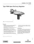
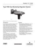
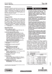
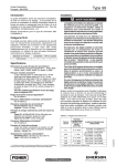
1
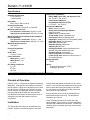
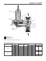
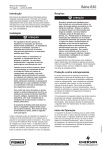
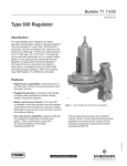
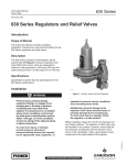
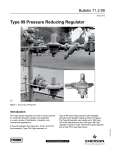
Bulletin 71.4:630R
December 2011
type 630r relief Valve
W1934
Figure 1. Type 630R Relief Valve
Introduction
The Type 630R is a general relief valve that is
available in NPS 1 and 2 / DN 25 and 50 body sizes.
It is frequently used at compressor stations, refi neries and similar plants requiring a backpressure gas
regulator for relief pressure settings up to 250 psig /
17.2 bar.
Features
• Tight Shutoff—Provided by an O-ring seat.
• Easy Maintenance—The inlet adaptor acts as a
union nut enabling speedy inspection of trim parts.
• Interchangeability—The Type 630R relief valve
can be easily converted in the fi eld to a Type 630 regulator by reversing the actuator and using a new
valve carrier, disk, and orifi ce. • Sour Gas Service Capability—Optional materials
are available for applications handling sour
gases. These constructions comply with the
recommendations of NACE International Standards
MR0175 and MR0103.
D100158X012
• Ease of Use—The Type 630R is available in both
high-pressure and low pressure constructions; the
low pressure units have larger diaphragm area
to provide more accurate control of low pressure
settings while the high-pressure units can withstand
inlet pressure up to 550 psig / 37.9 bar and can
control pressures up to 250 psig / 17.2 bar.
www.fisherregulators.com
Bulletin 71.4:630R
Specifications
Regulator Construction
• Low-Pressure
• High-Pressure
Body Sizes
NPS 1 and 2 / DN 25 and 50
End Connection Style
NPT, CL150 RF, CL300 RF, or CL600 RF
Maximum Inlet Pressure(1)
Low-Pressure Construction: 66 psig / 4.6 bar
High-Pressure Construction: 550 psig / 37.9 bar
Maximum Inlet Pressure Build-up above Setpoint
(Internal Damage)
Low-Pressure Construction: 25 psig / 1.7 bar
High-Pressure Construction: 250 psig / 17.2 bar
Maximum Outlet Pressure(1)
See Table 1
Pressure Registration
Internal
Orifice Size
1/2-inch / 13 mm
Flow Coefficients
Wide-open Cg: 216.0
Wide-open Cv: 8.18
C1: 26.4
IEC Sizing Coefficients
Fd: 0.50
Fl: 0.89
Xt: 0.441
Temperature Capabilities(1)
Nitrile (NBR), Nylon (PA), and Neoprene (CR): -20° to 180°F / -29° to 82°C
Fluorocarbon (FKM) and
Polytetrafluoroethylene (PTFE):
0° to 300°F / -18° to 149°C
Construction Materials
Body: Cast iron or steel
Spring Case and Diaphragm Adaptor:
Cast iron or steel
Orifice: Brass or Stainless steel
O-ring Holder: Brass or Stainless steel
Valve Carrier: Brass or Stainless steel
Diaphragm: Neoprene (CR) or Fluorocarbon (FKM)
Diaphragm Head: Zinc-plated steel
Pitot Tube: Stainless steel
Regulator Spring: Plated steel
Adjusting Screw: Steel
Inlet Body Gaskets: Copper with Brass trim or Stainless steel with Stainless steel trim
All Other Gaskets: Composition
Upper Spring Seat: Zinc-plated steel
Lower Spring Seat: Aluminum (low-pressure) or Zinc (high-pressure)
Spring Case Vent
1/4 NPT
Option
• Polytetrafluoroethylene (PTFE)
diaphragm protector
1. The pressure/temperature in this Bulletin and any applicable standard or code limitation should not be exceeded.
Principle of Operation
Refer to Figure 2. Inlet pressure registers beneath the
diaphragm. As long as the inlet pressure is less than
the set pressure, spring force causes the lever to hold
the valve closed. When the inlet pressure exceeds
the set pressure, the diaphragm moves to compress
the spring and the lever opens the valve allowing
inlet pressure to bleed into the downstream line or to
atmosphere until the inlet pressure returns to
set pressure.
Installation
The Type 630R relief valve may be installed in any
position. However, the outlet connection and vents
2
must be protected against the entrance of rain, snow,
insects, or any other foreign material that may plug the
outlet or affect the opening and closing of the valve.
If it is necessary to pipe away the outlet, remove the
outlet screen (if one is present).
Flow through the valve must be as indicated by the
flow direction arrow on the body. For dimensional
information see Figure 3.
Fisher® provides an instruction manual with every
valves shipped. Refer to this for complete installation,
operation and maintenance instructions. Included is a
complete listing of individual parts and recommended
spare parts.
Bulletin 71.4:630R
spring case
lever
diaphragm
body
orifice
diaphragm
connector
O-ring holder
valve carrier
diaphragm
adaptor
A6674
inlet pressure
OUTLET (EXHAUST) PRESSURE
atmospheric pressure
Figure 2. Type 630R Relief Valve Operational Schematic
Table 1. Relief Set Pressure Ranges
REGULAR CONSTRUCTION
Low-Pressure
High-Pressure
Relief Set PRESSURE
RANGE
Spring Part
Number
Spring
Color Code
SPRING WIRE DIAMETER
psig
bar
Inches
mm
3 to 8
0.21 to 0.55
0W019227022
Red
0.225
5.71
6 to 17
0.41 to 1.2
0W019127022
Olive Drab
0.281
7.14
15 to 22
1.0 to 1.5
0W019027022
Unpainted
0.337
8.56
20 to 35
1.4 to 2.4
0Y066427022
Green Stripe
0.363
9.22
35 to 50
2.4 to 3.4
1J146927142
Blue Stripe
0.375
9.52
30 to 70
2.1 to 4.8
0W019127022
Olive Drab
0.281
7.14
50 to 95
3.4 to 6.6
0W019027022
Unpainted
0.337
8.56
75 to 175
5.2 to 12.1
0Y066427022
Green Stripe
0.363
9.22
150 to 250
10.3 to 17.2
1J146927142
Blue Stripe
0.375
9.52
SPRING FREE LENGTH
Inches
mm
6
152
6.19
157
6
152
6.19
157
3
Bulletin 71.4:630R
Universal NACE Compliance
Optional materials are available for applications
handling sour gases. These constructions comply
with the recommendations of NACE International sour
service standards.
The manufacturing processes and materials used
by Emerson assure that all products specified
for sour gas service comply with the chemical,
physical, and metallurgical requirements of
NACE MR0175 and/or NACE MR0103. Customers
have the responsibility to specify correct materials.
Environmental limitations may apply and shall be
determined by the user.
the factors in the preceding paragraph
if necessary:
Q = (P1 + build-up)absCg
1. To determine capacities at set pressures or
build-ups not given in Table 2, use one of
the following formulas, and convert according to
GT
2. For pressure drops lower than critical (absolute
outlet pressure greater than one-half of absolute
inlet pressure), use the following formula:
Q=
Capacity Information
Table 2 gives relief capacities at selected set
pressures for the Type 630R relief valve. Flows
are in SCFH (60°F and 14.7 psia) and Nm³/h (0°C
and 1.01325 bar) of 0.6 specific gravity natural gas. To determine equivalent capacities for air, propane,
butane, or nitrogen, multiply the Table 2 capacity
by the following appropriate conversion factor:
0.775 for air, 0.625 for propane, 0.547 for butane,
or 0.789 for nitrogen. For gases of other specific
gravities, multiply the given capacity by 0.775,
and divide by the square root of the appropriate
specific gravity.
520
3417
520
Cg (P1 + build-up)abs SIN
C1
GT
P
P1
Deg.
where,
Q = flow capacity in SCFH
G = specific gravity of gas
T = abosolute temperature of gas at inlet in
°Rankine (°Rankine = °Fahrenheit + 460)
Cg = sizing coefficient (See
Specifications section)
P1abs = absolute inlet pressure in psig
(P1 gauge + 14.7)
C1 = Cg/Cv (See Specifications section)
P = pressure drop across the valve in psig
Table 2. Capacities in SCFH / Nm3/h of 0.6 Specific Gravity Natural Gas at 14.7 psia and 60°F / 1.01325 bar and 0°C
LOW-PRESSURE CONSTRUCTION
HIGH-PRESSURE CONSTRUCTION
Capacities, SCFH / Nm3/h
Relief Pressure Setting
10% Build-up
20% Build-up
Capacities, SCFH / Nm3/h
psig
bar
psig
bar
5
10
15
0.34
0.69
1.0
640
1420
2000
17.2
38.1
53.6
2710
2900
4200
72.6
77.7
113
50
75
100
3.4
5.2
6.9
2900
2700
3260
77.7
72.4
87.4
7100
7480
9670
190
200
259
20
35
50
1.4
2.4
3.4
2130
3030
4900
57.1
81.2
131
4450
7230
14,000
119
194
375
125
175
250
8.6
12.1
17.2
5500
5480
13,500
147
147
362
14,200
19,000
48,000
381
509
1286
Note: Maximum Working Pressure Above Setting is 25 psig / 1.7 bar.
4
Relief Pressure Setting
10% Build-up
20% Build-up
Note: Maximum Working Pressure Above Setting is 250 psig / 17.2 bar.
Bulletin 71.4:630R
L
D
d
A
B
F
AA7679
NPT
or
SWE
G
Type 630R with NPT body
Figure 3. NPT Dimensions
Table 3. NPT Dimensions
NPT DIMENSIONS, inches / mm
Body Size, NPS
1
2
Low-Pressure Assembly
a
B
D
F
G
L
7.38 / 187
7.88 / 200
3.69 / 94
3.94 / 100
7.12 / 181
7.12 / 181
10.31 / 262
10.94 / 278
1.38 / 35
2.00 / 51
15.88 / 403
16.38 / 416
1.38 / 35
2.00 / 51
15.88 / 403
16.38 / 416
Body Size, NPS
1
2
High-Pressure Assembly
7.38 / 187
7.88 / 200
3.69 / 94
3.94 / 100
4.62 / 117
4.62 / 117
7.81 / 198
8.44 / 214
5
Bulletin 71.4:630R
E
F
D
A
C
A/2
B
16A7430
Type 630R with Flanged body
Figure 4. Flange Dimensions
Table 4. Flange Dimensions
FLANGED DIMENSIONS, inches / mm
Low-Pressure Assembly
Body Size,
NPS / DN
a
CL150
CL300
CL150
CL300
1 / 25
19.59 / 498
9.80 / 249
2 / 50
21.9 / 556
10.95 / 278
Body Size,
NPS / DN
6
A/2
CL600
CL600
B
C
D
E
F
8.97 /
228
7.19 /
183
7.12 /
181
11.69 /
297
1.75 /
44
6.44 /
163
4.69 /
119
4.62 /
117
12.19 /
310
1.38 /
35
High-Pressure Assembly
1 / 25
19.59 / 498
9.80 / 249
2 / 50
17.6 / 447
8.8 / 223
Bulletin 71.4:630R
Ordering Information
When ordering, specify the following information:
1. Complete Type number
2. Body Size
3. Relief Setting
4. Body Material
5. Trim
Ordering Guide
Regulator Construction (Select One)
Low-Pressure
High-Pressure
Trim Material (Select One)
Brass***
Stainless steel**
Valve Carrier and Holder (Select One)
Brass***
Stainless steel**
Orifice (Select One)
Brass***
Stainless steel**
Relief Set Pressure Range (Select One)
Body Size (Select One)
NPS 1 / DN 25**
NPS 2 / DN 50**
Low-Pressure
3 to 8 psig / 0.21 to 0.55 bar***
6 to 17 psig / 0.41 to 1.2 bar***
15 to 22 psig / 1.0 to 1.5 bar***
20 to 35 psig / 1.4 to 2.4 bar***
35 to 50 psig / 2.4 to 3.4 bar***
Body and End Connection Style (Select One)
NPT**
CL150 RF**
CL300 RF**
CL600 RF**
High-Pressure
30 to 70 psig / 2.1 to 4.8 bar***
50 to 95 psig / 3.4 to 6.6 bar***
75 to 175 psig / 5.2 to 12.1 bar***
150 to 250 psig / 10.3 to 17.2 bar***
Diaphragm (Select One)
Neoprene (CR)***
Fluorocarbon (FKM)**
Replacement Parts Kit (Optional)
Yes, send one replacement parts kit to match
this order. Specification Worksheet
Regulators Quick Order Guide
***
**
*
Application:
Specific Use
Line Size
Gas Type and Specific Gravity
Gas Temperature
Relief Valve Size:
Brand of upstream regulator? Orifice size of the upstream regulator?
Wide-open coefficient of the upstream regulator?
Pressure:
Maximum Inlet Pressure (P1max)
Minimum Inlet Pressure (P1min)
Downstream Pressure Setting(s) (P2)
Maximum Flow (Qmax)
Allow Additional Time for Shipment
Performance Required:
Accuracy Requirements?
Need for Extremely Fast Response?
Special Order, Constructed from Non-Stocked Parts.
Consult your local Sales Office for Availability.
Other Requirements:
Readily Available for Shipment
Availability of the product being ordered is determined by the component with the
longest shipping time for the requested construction.
7
Bulletin 71.4:630R
Industrial Regulators
Natural Gas Technologies
TESCOM
Emerson Process Management
Regulator Technologies, Inc.
Emerson Process Management
Regulator Technologies, Inc.
Emerson Process Management
Tescom Corporation
USA - Headquarters
McKinney, Texas 75069-1872, USA
Tel: +1 800 558 5853
Outside U.S. +1 972 548 3574
USA - Headquarters
McKinney, Texas 75069-1872, USA
Tel: +1 800 558 5853
Outside U.S. +1 972 548 3574
USA - Headquarters
Elk River, Minnesota 55330-2445, USA
Tels: +1 763 241 3238
+1 800 447 1250
Asia-Pacific
Shanghai 201206, China
Tel: +86 21 2892 9000
Asia-Pacific
Singapore 128461, Singapore
Tel: +65 6770 8337
Europe
Selmsdorf 23923, Germany
Tel: +49 38823 31 287
Europe
Bologna 40013, Italy
Tel: +39 051 419 0611
Europe
Bologna 40013, Italy
Tel: +39 051 419 0611
Gallardon 28320, France
Tel: +33 2 37 33 47 00
Asia-Pacific
Shanghai 201206, China
Tel: +86 21 2892 9499
Middle East and Africa
Dubai, United Arab Emirates
Tel: +971 4811 8100
For further information visit www.emersonprocess.com/regulators
The Emerson logo is a trademark and service mark of Emerson Electric Co. All other marks are the property of their prospective owners. Fisher is a mark owned by Fisher Controls International LLC,
a business of Emerson Process Management.
The contents of this publication are presented for informational purposes only, and while every effort has been made to ensure their accuracy, they are not to be construed as warranties or
guarantees, express or implied, regarding the products or services described herein or their use or applicability. We reserve the right to modify or improve the designs or specifications of such
products at any time without notice.
Emerson Process Management does not assume responsibility for the selection, use or maintenance of any product. Responsibility for proper selection, use and maintenance of any Emerson
Process Management product remains solely with the purchaser.
©Emerson Process Management Regulator Technologies, Inc., 1970, 2011; All Rights Reserved