1
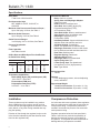
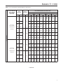
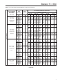
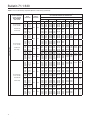
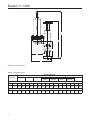
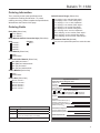
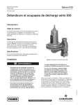
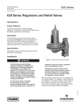
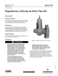
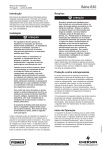
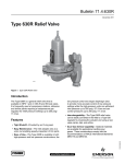
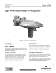
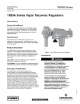
Bulletin 71.1:630
December 2012
Type 630 Regulator
Introduction
The Type 630 Big Joe™ regulators are directoperated, spring-loaded, pressure reducing regulators.
They are available in 1 and 2-inch / DN 25 and 50
body sizes, and they are designed for maximum inlet
pressures to 1500 psig / 103 bar and outlet pressures
from 3 to 500 psig / 0.21 to 34.5 bar. The Type 630
can be used with natural gas, air, or a variety of other
gasesforsuchapplicationsasfirst-stagefarm-tap
regulators or high-pressure industrial regulators.
TheType630canbeconvertedinthefieldtoa
relief valve or is available as the Type 630R relief
valve/backpressure regulator; refer to the separate
Type 630R Bulletin (71.4:630R) for information.
Features
• High-Pressure Capabilities—Inlet pressures up
to 1500 psig / 103 bar and control pressures up to
500 psig / 34.5 bar.
• Rugged Construction—Compact, sturdy design
and solid metal construction provide a strong,
reliable, long-lasting regulator.
• Better Low-Pressure Control—The Type 630
is available in both high-pressure and low-pressure
constructions; the low-pressure units have a larger
diaphragm area to provide more accurate control of
low-pressure settings.
Figure 1. Type 630 Big Joe High-Pressure Regulator
The manufacturing processes and materials
used by Fisher® Controls assure that all products
specifiedforsourgasservicecomplywiththe
chemical and physical requirements of NACE
International MR0175.
D100121X012
• Sour Gas Service Capability—Optional materials
are available for applications handling sour
gases. These constructions comply with
the recommendations of the NACE
International MR0175.
W1934
www.fisherregulators.com
Bulletin 71.1:630
Specifications
Body Sizes
1 and 2-inch / DN 25 and 50
End Connection Style
NPT, ASME CL150 RF, CL300 RF, or
CL600 RF
Maximum Inlet Pressure and Pressure Drops(1)
Up to 1500 psig / 103 bar, See Table 1
Maximum Outlet Pressure(1)
Up to 500 psig / 34.5 bar, See Table 2
Outlet Pressure Ranges
3 to 500 psig / 0.21 to 34.5 bar, See Table 2
Pressure Registration
Internal
Flow Capacities
See Tables 3 and 4
Orifice Sizes and Wide-Open Flow Coefficients
for Relief Valve Sizing
ORIFICE SIZE
Inch
mm
1/8
3/16
1/4
3/8
1/2
3.2
4.8
6.4
9.5
13
Cg
CV
C1
13.9
31.3
55.1
122.5
216.0
0.49
1.11
2.03
4.61
8.18
28.4
28.2
27.2
26.6
26.4
Temperature Capabilities(1)
Nitrile (NBR), Nylon (PA), and Neoprene (CR):
-20 to 180°F / -29 to 82°C
Fluorocarbon (FKM) and
Polytetrafluoroethylene (PTFE):
0 to 300°F / -18 to 149°C
Construction Materials
Body: Cast iron, or steel
Spring Case and Diaphragm Adaptor:
Cast iron or steel
Orifice: Brass or stainless steel
Valve Disk: Nitrile (NBR), Nylon (PA),
Polytetrafluoroethylene (PTFE),
or Fluorocarbon (FKM)
Valve Disk Holder: Brass or stainless steel
Valve Carrier: Brass or stainless steel
Diaphragm: Neoprene (CR) or
Fluorocarbon (FKM)
Inlet Body Gaskets: Copper with brass trim or
stainless steel with stainless steel trim
All Other Gaskets: Composition
Lever: Zinc-plated steel or Stainless steel
Diaphragm Connector: Aluminum with brass
trim or stainless steel with stainless steel trim
Pitot Tube: Stainless steel
Regulator Spring: Plated steel
Adjusting Screw: Steel
Diaphragm Plate: Zinc-plated steel
Upper Spring Seat: Zinc
Lower Spring Seat: Zinc-plated steel
(low pressure) or Zinc (high pressure)
Vent: Type Y602-9
Spring Case Vent
1/4 NPT
Options
PTFE diaphragm protector, wire-seal adjusting
screw, and NACE
Approximate Weight
1-inch End Connection: 25 pounds / 11.3 kg
2-inch End Connection: 30 pounds / 13.6 kg
1. The pressure/temperature limits in this Bulletin and any applicable standard or code limitation should not be exceeded.
Installation
Overpressure Protection
These regulators may be installed in any position.
Some installations may require a remote vent line.
Protect all vent openings against the entrance of rain,
snow, debris, or any other foreign material that may
plug the opening.
As is the case with most regulators, these regulators
have an outlet pressure rating that is lower than the
inlet pressure rating. Overpressure protection is
needed if the actual inlet pressure can exceed the
outlet pressure rating.
Direction of flow through the regulator body must be
in the direction indicated by the flow direction arrow
found on the regulator body.
Regulator operation below the limits specified in
Tables 1 and 2 do not preclude the possibility of
damage from external sources or from debris in
the pipeline. The regulator should be inspected for
damage after any overpressure condition.
2
Bulletin 71.1:630
SPRING
CASE
LEVER
BODY
DIAPHRAGM
DIAPHRAGM
CONNECTOR
DIAPHRAGM
ADAPTOR
VALVE DISK
AND HOLDER
A6673
INLET PRESSURE
ORIFICE
OUTLET PRESSURE
ATMOSPHERIC PRESSURE
INLET ADAPTOR
W0428-3*
Figure 3. Type 630 Operational Schematic
FULL SECTION
PITOT TUBE
[1-INCH / DN 25 SIZE ONLY]
REGISTRATION HOLE
[2-INCH / DN 50 SIZE ONLY]
Principle of Operations
Refer to Figure 2. In the regulator construction, outlet
pressure registers beneath the diaphragm. As long
as the outlet pressure is less than the set pressure,
spring force on the diaphragm causes the lever to hold
the valve open. When the outlet pressure exceeds the
set pressure, the diaphragm moves to compress the
spring and the lever closes the valve until the outlet
pressure returns to set pressure.
Capacity Data
W0429-3*
BODY ONLY
(ROTATED 90°)
Flow capacities are given in Tables 3 and 4 in standard
cubic feet per hour (SCFH) and normal cubic meters
per hour (Nm3/h) of 0.6 specific gravity natural
gas. To determine the equivalent flow rate for other
gases, multiply the table value by the appropriate
factor: air—0.775; butane—0.547; nitrogen—0.789;
propane—0.627.
Figure 2. Type 630 Sectional Views
3
Bulletin 71.1:630
Table 1. Maximum Inlet Pressure and Pressure Drops
MAXIMUM ALLOWABLE PRESSURE DROPS
MAXIMUM ALLOWABLE
INLET PRESSURE(1)
ORIFICE SIZES
inches
mm
1/8 and 3/16
3.2 and 4.8
psig
1/4
6.4
3/8
9.5
1000
1/2
13
750
1500
bar
Nylon (PA) and
Polytetrafluoroethylene
(PTFE) Disk
psig
bar
1500
103
1000
69
69
500
34.5
51.7
250
17.2
103
Fluorocarbon (FKM) Disk
psig
bar
200
13.8
Nitrile (NBR) Disk
psig
bar
600
41.4
500
34.5
250
17.2
1. Inlet pressure must not exceed the sum of the actual outlet pressure setting and the maximum allowable pressure drop. For example, with an outlet pressure setting of 200 psig / 13.8 bar
and a 3/8-inch / 9.5 mm orifice with a maximum allowable pressure drop of 500 psid / 34.5 bar d, the maximum inlet pressure is 700 psig / 48.3 bar.
2. Nitrile (NBR) valve disks are normally furnished for pressure drops to 200 psi / 13.8 bar, differential. For better erosion resistance, Nylon (PA) valve disks are normally furnished for
higher pressure drops. Some erosion of valve disks occurs at all pressure drops due to solid particles in the flow stream. The rate of erosion is higher with large amounts of impurities in
the flow stream and with high pressure drops. Valve disks and other regulator parts must be inspected periodically for erosion and damage and must be replaced as necessary. Table 2. Outlet Pressure Ranges
REGULATOR
CONSTRUCTION
Low pressure
OUTLET PRESSURE
RANGE
SPRING
PART
NUMBER
SPRING
COLOR
CODE
SPRING WIRE
DIAMETER
SPRING FREE
LENGTH
inches
psig
bar
inches
mm
3 to 10
0.21 to 0.69
0W019227022
Red stripe
0.23
5.84
8 to 20
0.55 to 1.4
0W019127022
Olive green
0.28
7.11
17 to 30
1.2 to 2.1
0W019027022
Unpainted
0.34
27 to 40
1.9 to 2.8
0Y066427022
Green stripe
0.36
psig
bar
20
1.4
8.64
20(2)
1.4(2)
9.14
Limited by
Maximum
Emergency
Outlet Pressure
6.0
High pressure
1.
2.
3.
4.
1.9 to 3.4
0W019227022
Red stripe
0.23
5.84
46 to 95
3.2 to 6.6
0W019127022
Olive green
0.28
7.11
90 to 150
6.2 to 10.3
0W019027022
Unpainted
0.34
8.64
150 to 200
10.3 to 13.8
0Y066427022
Green stripe
0.36
9.14
200 to 275
13.8 to 19.0
1J146927142
Blue stripe
0.38
9.65
6.1
155
275 to 500
19.0 to 34.5
1K370927082
Yellow stripe
0.44
11.2
6.2
157
200
13.8
200(3)
13.8(3)
MAXIMUM
EMERGENCY
OUTLET
(CASING)
PRESSURE(4)
psig
bar
66
4.6
550
37.9
Damage to internal parts of the regulator may occur if outlet pressure exceeds the actual pressure setting by amounts greater than those shown in this column.
For outlet pressure settings to 25 psig / 1.7 bar only. For pressure settings over 25 psig / 1.7 bar, outlet pressure is limited by maximum emergency outlet pressure of 45 psig / 3.1 bar.
For outlet pressure settings to 350 psig / 24.1 bar only. For pressure settings over 350 psig / 24.1 bar, outlet pressure is limited by maximum emergency outlet pressure of 550 psig / 37.9 bar.
Leakage or bursting of pressure-containing parts may occur if outlet pressure exceeds these values.
1. If flow is critical (absolute outlet pressure is
equal to or less than one-half the absolute inlet
pressure), use the equation:
4
152
27 to 50
To determine the wide-open capacity for relief sizing
with the flow coefficients (Cg), use the appropriate
procedure below.
mm
MAXIMUM
OUTLET
PRESSURE
OVER
SETPOINT(1)
Flow = (Absolute Inlet Pressure) (Cg) (1.29)
The flow determined will be in SCFH of 0.6
specific gravity natural gas. To convert SCFH to
Nm3/h multiply the SCFH result by 0.0268.
2. If flow is less than critical (absolute outlet
pressure is greater than one-half the absolute
inlet pressure), use Fisher®’s computerized sizing
program or contact your local Sales Office.
Bulletin 71.1:630
Table 3. 1-Inch / DN 25 Body Capacities (Based on 20% Droop)
OUTLET PRESSURE
RANGE, SPRING
PART NUMBER,
AND COLOR
3 to 10 psig /
0.21 to 0.69 bar
0W019227022
LOW PRESSURE
Red Stripe
8 to 20 psig /
0.55 to 1.4 bar
0W019127022
Olive Drab
INLET
PRESSURE
1-INCH / DN 25 BODY CAPACITIES IN SCFH / Nm3/h
OF 0.6 SPECIFIC GRAVITY OF NATURAL GAS
OUTLET
PRESSURE
Orifice Size, Inches / mm
1/8 / 3.2
psig
bar
10
20
30
50
60
0.69
1.4
2.1
3.4
4.1
100
200
6.9
13.8
400
500
600
1000
1500
psig
1/4 / 6.4
3/8 / 9.5
1/2 / 13
SCFH
Nm /h
SCFH
Nm /h
SCFH
Nm /h
SCFH
Nm /h
SCFH
Nm3/h
200
400
600
950
1100
5
11
16
25
29
510
770
1100
1500
1750
14
21
29
40
47
990
1200
1500
2100
2400
27
32
40
56
64
1700
2000
2200
2800
3000
46
54
59
75
80
2200
2700
3300
4200
4100
59
72
88
113
110
1700
3000
46
80
2400
3400
64
91
2900
4200
78
113
4000
5100
107
137
4900
6100
131
163
27.6
34.5
41.4
69.0
103
3700
4100
4300
4600
5000
99
110
115
123
134
3900
4300
4600
4900
5400
105
115
123
131
145
4500
4700
5000
5600
----
121
126
134
150
----
6400
7400
----------
172
198
----------
----------------
----------------
20
30
50
60
1.4
2.1
3.4
4.1
500
700
1000
1150
13
19
27
31
1200
1400
2300
2700
32
38
62
72
1800
2800
4100
4200
48
75
110
113
4200
4100
5100
5500
113
110
137
147
4900
5300
6200
6500
131
142
166
174
100
200
400
6.9
13.8
27.6
1600
3300
5400
43
88
145
3800
5800
6900
102
155
185
5000
6900
7600
134
185
204
6400
7700
9000
172
206
241
7300
8200
----
196
220
----
500
600
1000
1500
34.5
41.4
69.0
103
6000
6500
7200
7400
161
174
193
198
7100
7300
7700
8400
190
196
206
225
7900
8200
8400
----
212
220
225
----
9700
----------
260
----------
-------------
-------------
20
30
50
60
1.4
2.1
3.4
4.1
500
700
900
1050
13
19
24
28
700
1300
1900
2300
19
35
51
62
1400
2100
3200
3500
38
56
86
94
2200
3100
4300
4700
59
83
115
126
3600
4300
5400
5800
96
115
145
155
100
200
400
6.9
13.8
27.6
1600
3300
5400
43
88
145
3500
4800
6500
94
129
174
4600
6200
7600
123
166
204
5700
7500
8900
153
201
239
6900
8200
----
185
220
----
500
600
1000
1500
34.5
41.4
69.0
103
6000
6500
7200
7400
161
174
193
198
6900
7000
7700
8100
185
188
206
217
7900
8200
8400
----
212
220
225
----
9400
----------
252
----------
-------------
-------------
20
30
50
60
1.4
2.1
3.4
4.1
470
600
1000
1150
13
16
27
31
1000
1500
2300
2700
27
40
62
72
1700
2500
3800
4300
46
67
102
115
3300
4600
5500
6100
88
123
147
163
4900
5200
5700
6800
131
139
153
182
100
200
400
6.9
13.8
27.6
1900
3600
7100
51
96
190
4300
7500
8700
115
201
233
6200
8500
10,000
166
228
268
7600
9600
11,000
204
257
295
9600
10,000
----
257
268
----
500
600
1000
1500
34.5
41.4
69.0
103
8300
8600
9600
10,000
222
230
257
268
8800
9600
10,000
11,000
236
257
268
295
10,500
10,800
11,000
----
281
289
295
----
12,000
----------
322
----------
-------------
-------------
5
10
10
15
bar
3/16 / 4.8
0.34
0.69
0.69
1.0
3
3
3
3
- continued -
5
Bulletin 71.1:630
Table 3. 1-Inch / DN 25 Body Capacities (Based on 20% Droop) (continued)
OUTLET PRESSURE
RANGE, SPRING
PART NUMBER,
AND COLOR
8 to 20 psig /
0.55 to 1.4 bar
0W019127022
LOW PRESSURE
Olive Drab
17 to 30 psig /
1.17 to 2.1 bar
0W019027022
Silver
27 to 40 psig /
1.9 to 2.8 bar
0Y066427022
Green Stripe
INLET
PRESSURE
1-INCH / DN 25 BODY CAPACITIES IN SCFH / Nm3/h
OF 0.6 SPECIFIC GRAVITY OF NATURAL GAS
OUTLET
PRESSURE
Orifice Size, Inches / mm
1/8 / 3.2
psig
bar
30
40
50
60
2.1
2.8
3.4
4.1
100
200
400
6.9
13.8
27.6
500
600
1000
1500
psig
3/8 / 9.5
1/2 / 13
Nm3/h
SCFH
Nm3/h
SCFH
Nm3/h
SCFH
Nm3/h
SCFH
Nm3/h
600
800
1000
1150
16
21
27
31
1500
2000
2300
2700
40
54
62
72
2500
3400
4200
4900
67
91
113
131
4600
5700
6800
7500
123
153
182
201
6800
8100
9000
9800
182
217
241
263
1800
3600
7200
48
96
193
4100
8000
10,000
110
214
268
7400
10,000
13,000
198
268
348
9500
12,000
14,000
255
322
375
11,000
13,000
----
295
348
----
34.5
41.4
69.0
103
8500
10,000
11,000
12,000
228
268
295
322
10,800
12,000
12,300
13,000
289
322
330
348
13,400
13,800
15,000
----
359
370
402
----
14,800
----------
397
----------
-------------
-------------
30
40
50
60
2.1
2.8
3.4
4.1
590
790
900
1050
16
21
24
28
900
1700
2200
2500
24
46
59
67
1700
2400
3600
4000
46
64
96
107
3300
4000
4900
5500
88
107
131
147
4700
6100
6900
7400
126
163
185
198
100
200
400
6.9
13.8
27.6
1700
3400
7000
46
91
188
4000
6400
8700
107
172
233
5500
9100
11,000
147
244
295
7600
11,000
13,000
204
295
348
9700
12,000
----
260
322
----
500
600
1000
1500
34.5
41.4
69.0
103
8000
9600
10,000
12,000
214
257
268
322
9800
11,000
12,000
13,000
263
295
322
348
11,800
13,000
14,000
----
316
348
375
----
13,700
----------
367
----------
-------------
-------------
40
50
60
100
2.8
3.4
4.1
6.9
820
900
1100
1700
22
24
29
46
1700
2200
2600
4100
46
59
70
110
2700
3600
4400
6800
72
96
118
182
5100
6400
7500
10,000
137
172
201
268
7600
8700
9800
12,000
204
233
263
322
200
400
500
13.8
27.6
34.5
3500
6900
8800
94
185
236
8000
13,000
14,000
214
348
375
11,000
15,000
15,600
295
402
418
14,000
17,000
18,500
375
456
496
16,000
-------
429
-------
600
1000
1500
41.4
69.0
103
9700
15,500
16,400
260
415
440
15,000
17,800
18,500
402
477
496
16,000
17,900
----
429
480
----
----------
----------
----------
----------
40
50
60
100
2.8
3.4
4.1
6.9
800
900
1100
1700
21
24
29
46
1500
2000
2500
3900
40
54
67
105
2400
3200
3900
6400
64
86
105
172
4400
5600
6300
9400
118
150
169
252
6400
7700
8900
11,000
172
206
239
295
200
400
500
13.8
27.6
34.5
3500
6900
8800
94
185
236
7000
12,000
12,500
188
322
335
9400
15,000
15,600
252
402
418
14,000
17,000
17,800
375
456
477
15,000
-------
402
-------
600
1000
1500
41.4
69.0
103
9700
15,600
16,400
260
418
440
13,400
15,800
18,000
359
423
482
16,000
17,900
----
429
480
----
----------
----------
----------
----------
50
60
100
3.4
4.1
6.9
950
1100
1800
25
29
48
1800
2300
4100
48
67
110
3200
4100
7000
86
110
188
5500
7500
11,000
147
201
295
8900
10,000
14,000
239
268
375
200
400
500
600
13.8
27.6
34.5
41.4
3500
7100
8800
9800
94
190
236
263
7800
15,000
16,500
18,000
209
402
442
482
12,000
18,000
18,700
21,000
322
482
501
563
17,000
21,000
21,700
----
456
563
582
----
19,000
----------
509
----------
1000
1500
69.0
103
16,800
20,000
450
536
19,800
22,000
531
590
22,800
----
611
----
-------
-------
-------
-------
20
30
30
40
1.4
1.4
2.1
2.1
2.8
- continued -
6
1/4 / 6.4
SCFH
20
bar
3/16 / 4.8
Bulletin 71.1:630
Table 3. 1-Inch / DN 25 Body Capacities (Based on 20% Droop) (continued)
OUTLET PRESSURE
RANGE, SPRING
PART NUMBER,
AND COLOR
27 to 50 psig /
1.9 to 3.4 bar
0W019227022
Red Stripe
46 to 95 psig /
3.2 to 6.6 bar
0W019127022
HIGH PRESSURE
Olive Drab
90 to 150 psig /
6.2 to 10.3 bar
0W019027022
Sliver
150 to 200 psig /
10.3 to 13.8 bar
0Y066427022
Green Stripe
INLET
PRESSURE
1-INCH / DN 25 BODY CAPACITIES IN SCFH / Nm3/h
OF 0.6 SPECIFIC GRAVITY OF NATURAL GAS
OUTLET
PRESSURE
Orifice Size, Inches / mm
1/8 / 3.2
psig
60
100
200
300
400
500
600
1000
1500
60
100
200
300
400
500
600
1000
1500
100
200
400
500
600
1000
1500
125
150
200
300
400
500
1000
1500
150
200
300
400
500
1000
1500
200
300
400
500
800
1000
1500
200
300
400
500
800
1000
1500
bar
4.1
6.9
13.8
20.7
27.6
34.5
41.4
69.0
103
4.1
6.9
13.8
20.7
27.6
34.5
41.4
69.0
103
6.9
13.8
27.6
34.5
41.4
69.0
103
8.62
10.3
13.8
20.7
27.6
34.5
69.0
103
10.3
13.8
20.7
27.6
34.5
69.0
103
13.8
20.7
27.6
34.5
55.2
69.0
103
13.8
20.7
27.6
34.5
55.2
69.0
103
psig
bar
50
3.4
50
3.4
75
5.17
100
6.9
125
8.62
150
10.3
150
10.3
SCFH
900
1700
3500
5300
6900
8700
9800
16,200
19,000
800
1500
3400
5200
6800
8600
9800
13,500
18,000
1700
3500
7100
8600
9900
16,700
23,000
2000
2500
3600
5300
7000
8300
17,500
25,000
2400
3500
5200
7300
7900
16,000
26,000
3400
5300
7100
8000
13,000
17,000
26,000
3400
5300
7100
8000
13,000
16,700
26,000
Nm3/h
24
46
94
142
185
233
263
434
509
21
40
91
139
182
230
263
362
482
46
94
190
230
265
448
616
54
67
96
142
188
222
469
670
64
94
139
196
212
429
697
91
142
190
214
348
456
697
91
142
190
214
348
448
697
3/16 / 4.8
SCFH Nm3/h
2000
54
3500
94
7800
209
10,500
281
13,000
348
15,000
402
17,000
456
22,300
598
25,000
670
1500
40
3100
83
6800
182
8900
239
11,000
295
12,300
330
14,000
375
18,400
493
24,000
643
3200
86
7300
196
14,000
375
16,300
437
19,000
509
25,800
691
32,000
858
3600
96
4600
123
6600
177
9800
263
13,000
348
15,500
415
26,000
697
35,000
938
4600
123
6800
182
10,000
268
14,500
389
15,000
402
30,300
812
43,000 1152
6800
182
10,000
268
14,000
375
18,800
504
29,000
777
34,000
911
47,000 1260
6200
166
10,000
268
14,000
375
16,500
442
27,000
724
31,000
831
44,000 1179
1/4 / 6.4
SCFH
3100
5700
11,000
14,000
17,000
19,000
21,000
26,300
---2400
4200
9400
11,000
15,000
16,300
19,000
21,700
---5000
10,000
19,000
21,300
25,000
31,000
---5500
6800
9400
14,000
18,000
20,500
32,600
---6700
10,000
15,000
19,000
25,000
38,800
---10,000
15,000
22,000
26,300
38,000
44,300
---9300
15,000
21,000
26,300
37,000
43,900
----
Nm3/h
83
153
295
375
456
509
563
705
---64
113
252
295
402
437
509
582
---134
268
509
571
670
831
---147
182
252
375
482
549
874
---180
268
402
509
670
1040
---268
402
590
705
1018
1187
---249
402
563
705
992
1177
----
3/8 / 9.5
SCFH Nm3/h
5200
139
10,500
281
16,000
429
20,000
536
23,000
616
25,000
670
------------------4300
115
7500
201
14,000
375
16,000
429
20,000
536
22,000
590
------------------8000
214
16,000
429
27,000
724
28,700
769
------------------9200
247
11,000
295
13,000
348
21,000
563
27,000
724
31,000
831
------------11,000
295
15,000
402
25,000
670
29,000
777
36,000
965
------------16,000
429
24,000
643
34,000
911
39,300 1053
------------------16,000
429
24,000
643
32,000
858
39,000 1045
-------------------
1/2 / 13
SCFH
8100
13,000
19,000
23,000
---------------6400
10,000
17,000
20,000
---------------13,000
22,000
---------------13,000
16,000
22,000
30,000
------------17,000
23,000
34,000
------------26,000
35,000
42,000
------------26,000
30,000
38,000
-------------
Nm3/h
217
348
509
616
---------------172
268
456
536
---------------348
590
---------------348
429
590
804
------------456
616
911
------------697
938
1126
------------697
804
1018
-------------
- continued -
7
Bulletin 71.1:630
Table 3. 1-Inch / DN 25 Body Capacities (Based on 20% Droop) (continued)
OUTLET PRESSURE
RANGE, SPRING
PART NUMBER,
AND COLOR
150 to 200 psig /
10.3 to 13.8 bar
0Y066427022
Green Stripe
200 to 275 psig /
13.8 to 19.0 bar
HIGH PRESSURE
1J146927142
Blue Stripe
275 to 500 psig /
19.0 to 34.5 bar
1K370927082
Yellow Stripe
8
INLET
PRESSURE
1-INCH / DN 25 BODY CAPACITIES IN SCFH / Nm3/h
OF 0.6 SPECIFIC GRAVITY OF NATURAL GAS
OUTLET
PRESSURE
Orifice Size, Inches / mm
1/8 / 3.2
psig
bar
250
300
600
700
17.2
20.7
41.4
48.3
800
1000
1200
1500
55.2
69.0
82.7
103
250
300
600
700
17.2
20.7
41.4
48.3
800
1000
1200
1500
55.2
69.0
82.7
103
300
400
500
600
20.7
27.6
34.5
41.4
1000
1500
psig
1/4 / 6.4
3/8 / 9.5
1/2 / 13
SCFH
Nm3/h
SCFH
Nm3/h
SCFH
Nm3/h
SCFH
Nm3/h
SCFH
Nm3/h
4200
5200
9500
11,000
113
139
255
295
8300
10,000
22,000
25,000
222
268
590
670
12,000
16,000
34,000
40,000
322
429
911
1072
20,000
25,000
55,000
61,500
536
670
1474
1648
30,000
35,000
-------
804
938
-------
13,000
16,000
20,000
26,000
348
429
536
697
30,000
37,000
41,000
53,000
804
992
1099
1420
43,000
50,000
59,000
----
1152
1340
1581
----
-------------
-------------
-------------
-------------
4200
5200
9500
11,000
113
139
255
295
8200
10,000
22,000
25,000
220
268
590
670
11,000
14,500
31,000
35,000
295
389
831
938
20,000
25,000
51,000
55,000
536
670
1367
1474
29,000
35,000
-------
777
938
-------
13,000
16,000
19,000
26,000
348
429
509
697
29,000
36,000
41,000
51,000
777
965
1099
1367
42,000
50,000
55,000
----
1126
1340
1474
----
-------------
-------------
-------------
-------------
4900
7000
8500
9500
131
188
228
255
9000
14,000
18,000
22,000
241
375
482
590
15,000
23,000
29,000
34,000
402
616
777
911
28,000
40,000
51,000
59,000
750
1072
1367
1581
42,000
56,000
65,000
----
1126
1501
1742
----
69.0
103
16,000
26,000
429
697
39,000
59,000
1045
1581
58,000
----
1554
----
-------
-------
-------
-------
300
400
600
1000
1500
20.7
27.6
41.4
69.0
103
19.0
4700
6900
9300
16,000
26,000
126
185
249
429
697
9000
14,000
21,000
39,000
60,000
241
375
563
1045
1608
15,000
25,000
39,800
67,000
----
402
670
1067
1796
----
28,000
40,000
76,100
-------
750
1072
2039
-------
39,000
54,000
----------
1045
1447
----------
300
400
600
1000
1500
20.7
27.6
41.4
69.0
103
19.0
4500
6600
9300
17,000
26,000
121
177
249
456
697
7500
12,000
18,400
32,000
46,000
201
322
493
858
1233
10,000
16,000
24,300
43,000
----
268
429
651
1152
----
20,000
31,000
43,800
-------
536
831
1174
-------
31,000
43,000
----------
831
1152
----------
400
600
700
800
27.6
41.4
48.3
55.2
6600
9900
11,000
13,000
177
265
295
348
11,000
19,000
23,000
26,000
295
509
616
697
16,000
26,000
30,000
35,000
429
697
804
938
31,000
48,000
54,000
61,000
831
1286
1447
1635
42,000
----------
1126
----------
1000
1300
1500
69.0
89.6
103
16,800
22,000
26,000
450
590
697
32,500
43,000
49,000
871
1152
1313
43,800
58,000
----
1174
1554
----
----------
----------
----------
----------
500
600
800
900
1000
34.5
41.4
55.2
62.1
69.0
8300
9400
13,000
15,000
17,000
222
252
348
402
456
16,000
21,300
30,000
34,000
38,000
429
571
804
911
1018
24,000
30,000
41,000
49,000
54,000
643
804
1099
1313
1447
44,000
55,300
76,000
85,000
----
1179
1482
2037
2278
----
62,000
-------------
1662
-------------
1200
1400
1500
82.7
96.5
103
20,000
24,000
26,000
536
643
697
46,000
55,000
60,000
1233
1474
1608
63,000
76,000
----
1688
2037
----
----------
----------
----------
----------
550
600
900
1000
1500
37.9
41.4
62.1
69.0
103
8700
9500
15,000
17,000
26,000
233
255
402
456
697
16,000
19,000
34,000
39,000
59,000
429
509
911
1045
1581
26,000
36,800
52,000
60,000
72,000
697
986
1394
1608
1930
50,000
57,000
92,000
100,000
----
1340
1528
2466
2680
----
77,000
-------------
2064
-------------
200
200
250
275
275
300
400
500
bar
3/16 / 4.8
13.8
13.8
17.2
20.7
27.6
34.5
Bulletin 71.1:630
Table 4. 2-Inch / DN 50 Body Capacities (Based on 20% Droop)
OUTLET PRESSURE
RANGE, SPRING
PART NUMBER,
AND COLOR
3 to 10 psig /
0.21 to 0.69 bar
0W019227022
LOW PRESSURE
Red Stripe
8 to 20 psig /
0.55 to 1.4 bar
0W019127022
Olive Drab
INLET
PRESSURE
2-INCH / DN 50 BODY CAPACITIES IN SCFH / Nm3/h
OF 0.6 SPECIFIC GRAVITY OF NATURAL GAS
OUTLET
PRESSURE
Orifice Size, Inches / mm
1/8 / 3.2
psig
bar
10
20
30
50
60
0.69
1.4
2.1
3.4
4.1
100
200
6.9
13.8
400
500
600
1000
1500
psig
1/4 / 6.4
3/8 / 9.5
1/2 / 13
SCFH
Nm3/h
SCFH
Nm3/h
SCFH
Nm3/h
SCFH
Nm3/h
SCFH
Nm3/h
290
500
760
1100
1250
8
13
20
29
34
830
1200
1600
2200
2700
22
32
43
59
72
1300
2100
2700
3900
4500
35
56
72
105
121
3300
4800
7000
9800
11,100
88
129
188
263
297
5900
9100
11,000
17,000
19,500
158
244
295
456
523
1900
3700
51
99
4300
8200
115
220
7000
13,000
188
348
17,000
32,000
456
858
30,000
57,000
804
1528
27.6
34.5
41.4
69.0
103
7200
9100
10,000
18,000
22,000
193
244
268
482
590
16,000
19,000
24,000
39,000
60,000
429
509
643
1045
1608
28,000
35,000
42,000
69,000
----
750
938
1126
1849
----
64,000
79,000
----------
1715
2117
----------
----------------
----------------
20
30
50
60
1.4
2.1
3.4
4.1
560
770
1100
1250
15
21
29
34
1300
1500
2400
2800
35
40
64
75
2200
3000
4300
5000
59
80
115
134
5100
7000
9800
11,100
137
188
263
297
9000
11,000
17,000
19,500
241
295
456
523
100
200
400
6.9
13.8
27.6
1900
3700
7200
51
99
193
4400
8100
16,000
118
217
429
7600
14,000
28,000
204
375
750
17,000
33,000
62,000
456
884
1662
30,000
57,000
----
804
1528
----
500
600
1000
1500
34.5
41.4
69.0
103
8900
10,000
18,000
27,000
239
268
482
724
19,000
23,000
40,000
60,000
509
616
1072
1608
35,000
42,000
72,000
----
938
1126
1930
----
76,000
----------
2037
----------
-------------
-------------
20
30
50
60
1.4
2.1
3.4
4.1
550
760
1000
1200
15
20
27
32
1200
1500
2300
2700
32
40
62
72
1700
2500
3800
4500
46
67
102
121
2500
4600
7800
9900
67
123
209
265
4900
8800
16,000
18,500
131
236
429
496
100
200
400
6.9
13.8
27.6
1900
3600
7200
51
96
193
4300
8000
15,000
115
214
402
7400
14,000
28,000
198
375
750
17,000
32,000
60,000
456
858
1608
30,000
57,000
----
804
1528
----
500
600
1000
1500
34.5
41.4
69.0
103
8800
10,000
18,000
27,000
236
268
482
724
19,000
23,000
39,000
60,000
509
616
1045
1608
35,000
42,000
72,000
----
938
1126
1930
----
74,000
----------
1983
----------
-------------
-------------
20
30
50
60
1.4
2.1
3.4
4.1
520
740
1100
1250
14
20
29
34
1100
1600
2400
2800
29
43
64
75
1800
2800
4300
5000
48
75
115
134
3500
5900
9800
11,100
94
158
263
297
5700
10,000
16,000
18,500
153
268
429
496
100
200
400
6.9
13.8
27.6
1900
3700
7200
51
99
193
4400
8300
16,000
118
222
429
7800
14,000
29,000
209
375
777
17,000
31,000
64,000
456
831
1715
30,000
57,000
----
804
1528
----
500
600
1000
1500
34.5
41.4
69.0
103
9200
11,000
18,000
27,000
247
295
482
724
20,000
23,000
40,000
60,000
536
616
1072
1608
37,000
42,000
71,000
----
992
1126
1903
----
82,000
----------
2198
----------
-------------
-------------
5
10
10
15
bar
3/16 / 4.8
0.34
0.69
0.69
1.0
- continued -
9
Bulletin 71.1:630
Table 4. 2-Inch / DN 50 Body Capacities (Based on 20% Droop) (continued)
OUTLET PRESSURE
RANGE, SPRING
PART NUMBER,
AND COLOR
8 to 20 psig /
0.55 to 1.4 bar
0W019127022
LOW PRESSURE
Olive Drab
17 to 30 psig /
1.17 to 2.1 bar
0W019027022
Silver
27 to 40 psig /
1.9 to 2.8 bar
0Y066427022
Green Stripe
INLET
PRESSURE
2-INCH / DN 50 BODY CAPACITIES IN SCFH / Nm3/h
OF 0.6 SPECIFIC GRAVITY OF NATURAL GAS
OUTLET
PRESSURE
Orifice Size, Inches / mm
1/8 / 3.2
psig
bar
30
40
50
60
2.1
2.8
3.4
4.1
100
200
400
6.9
13.8
27.6
500
600
1000
1500
psig
3/8 / 9.5
1/2 / 13
Nm3/h
SCFH
Nm3/h
SCFH
Nm3/h
SCFH
Nm3/h
SCFH
Nm3/h
700
900
1100
1250
19
24
29
34
1600
2100
2400
2800
43
56
64
75
2600
3500
4300
5100
70
94
115
137
5200
7500
9400
11,000
139
201
252
295
9200
12,000
15,000
18,000
247
322
402
482
1900
3700
7300
51
99
196
4300
8200
16,000
115
220
429
7800
14,000
28,000
209
375
750
17,000
32,000
63,000
456
858
1688
29,000
59,000
----
777
1581
----
34.5
41.4
69.0
103
9100
11,000
17,700
27,000
244
295
474
724
19,300
24,000
39,200
60,000
517
643
1051
1608
35,500
43,000
71,600
----
951
1152
1919
----
78,800
----------
2112
----------
-------------
-------------
30
40
50
60
2.1
2.8
3.4
4.1
680
890
1000
1200
18
24
27
32
1300
1800
2300
2700
35
48
62
72
2100
2800
3700
4300
56
75
99
115
3500
5100
6200
7400
94
137
166
198
6000
8200
10,000
12,500
161
220
268
335
100
200
400
6.9
13.8
27.6
1900
3500
7100
51
94
190
4200
8000
15,000
113
214
402
6900
13,000
28,000
185
348
750
12,000
32,000
63,000
322
858
1688
24,000
56,000
----
643
1501
----
500
600
1000
1500
34.5
41.4
69.0
103
8900
10,000
17,700
27,000
239
268
474
724
19,200
24,000
39,200
60,000
515
643
1051
1608
35,500
42,000
70,600
----
951
1126
1892
----
78,800
----------
2112
----------
-------------
-------------
40
50
60
100
2.8
3.4
4.1
6.9
860
1000
1200
1800
23
27
32
48
1800
2300
2700
4200
48
62
72
113
2900
3800
4700
7800
78
102
126
209
5300
7300
8900
16,000
142
196
239
429
8500
11,000
14,000
28,000
228
295
375
750
200
400
500
13.8
27.6
34.5
3600
7000
8900
96
188
239
8100
16,000
19,100
217
429
512
14,000
28,000
34,900
375
750
935
24,000
64,000
80,900
643
1715
2168
58,000
-------
1554
-------
600
1000
1500
41.4
69.0
103
10,000
18,400
27,000
268
493
724
23,000
39,800
61,000
616
1067
1635
42,000
70,900
----
1126
1900
----
----------
----------
----------
----------
40
50
60
100
2.8
3.4
4.1
6.9
850
1000
1200
1800
23
27
32
48
1600
2200
2600
4200
43
59
70
113
2600
3500
4200
6900
70
94
113
185
4500
5900
7300
12,000
121
158
196
322
7200
9700
12,000
23,000
193
260
322
616
200
400
500
13.8
27.6
34.5
3600
7000
8900
96
188
239
8100
15,000
18,800
217
402
504
13,000
28,000
34,900
348
750
935
24,000
64,000
80,200
643
1715
2149
57,000
-------
1528
-------
600
1000
1500
41.4
69.0
103
10,000
18,400
27,000
268
493
724
23,000
39,700
61,000
616
1064
1635
42,000
70,800
----
1126
1897
----
----------
----------
----------
----------
50
60
100
3.4
4.1
6.9
1000
1200
1900
27
32
51
2100
2600
4300
56
70
115
3400
4300
7200
91
115
193
5900
7900
13,000
158
212
348
9900
12,000
24,000
265
322
643
200
400
500
600
13.8
27.6
34.5
41.4
3600
7200
8900
10,000
96
193
239
268
8200
16,000
19,600
23,000
220
429
525
616
14,000
28,000
35,100
42,000
375
750
941
1126
30,000
63,000
79,400
----
804
1688
2128
----
56,000
----------
1501
----------
1000
1500
69.0
103
17,300
27,000
464
724
39,400
61,000
1056
1635
70,200
----
1881
----
-------
-------
-------
-------
20
30
30
40
1.4
1.4
2.1
2.1
2.8
- continued -
10
1/4 / 6.4
SCFH
20
bar
3/16 / 4.8
Bulletin 71.1:630
Table 4. 2-Inch / DN 50 Body Capacities (Based on 20% Droop) (continued)
OUTLET PRESSURE
RANGE, SPRING
PART NUMBER,
AND COLOR
27 to 50 psig /
1.9 to 3.4 bar
0W019227022
Red Stripe
46 to 95 psig /
3.2 to 6.6 bar
HIGH PRESSURE
0W019127022
Olive Drab
90 to 150 psig /
6.2 to 10.3 bar
0W019027022
Silver
150 to 200 psig /
10.3 to 13.8 bar
0Y066427022
Green Stripe
INLET
PRESSURE
2-INCH / DN 50 BODY CAPACITIES IN SCFH / Nm3/h
OF 0.6 SPECIFIC GRAVITY OF NATURAL GAS
OUTLET
PRESSURE
Orifice Size, Inches / mm
1/8 / 3.2
psig
60
100
200
300
400
500
600
1000
1500
60
100
200
300
400
500
600
1000
1500
100
200
400
500
600
1000
1500
150
200
300
400
500
1000
1500
150
200
300
400
500
1000
1500
200
300
400
500
800
1000
1500
200
300
400
500
800
1000
1500
bar
4.1
6.9
13.8
20.7
27.6
34.5
41.4
69.0
103
4.1
6.9
13.8
20.7
27.6
34.5
41.4
69.0
103
6.9
13.8
27.6
34.5
41.4
69.0
103
10.3
13.8
20.7
27.6
34.5
69.0
103
10.3
13.8
20.7
27.6
34.5
69.0
103
13.8
20.7
27.6
69.0
55.2
69.0
103
13.8
20.7
27.6
34.5
55.2
69.0
103
psig
bar
50
3.4
50
3.4
75
5.17
100
6.9
125
8.62
150
10.3
150
10.3
SCFH
1000
1800
3600
5500
7000
8800
10,000
18,000
27,000
900
1600
3500
5300
6900
8700
10,000
17,100
26,000
1800
3600
7200
8700
10,000
17,600
24,000
2600
3700
5400
7200
8600
17,200
27,000
2500
3600
5300
7000
8800
17,000
27,000
3500
5400
7200
8600
14,000
18,000
27,000
3500
5400
7200
8500
14,000
17,400
27,000
Nm3/h
27
48
96
147
188
236
268
482
724
24
43
94
142
185
233
268
458
697
48
96
193
233
268
472
643
70
99
145
193
230
461
724
67
96
142
188
236
456
724
94
145
193
230
375
482
724
94
145
193
228
375
466
724
3/16 / 4.8
SCFH Nm3/h
2100
56
3600
96
7900
212
11,000
295
15,000
402
19,000
509
23,000
616
39,900 1069
60,000 1608
1600
43
3400
91
6700
180
10,000
268
13,000
348
16,300
437
20,000
536
38,700 1037
59,000 1581
3300
88
7400
198
15,000
402
19,000
509
23,000
616
39,000 1045
60,000 1608
4900
131
6900
185
10,000
268
14,000
375
17,500
469
38,600 1034
59,000 1581
5000
134
7400
198
11,000
295
15,000
402
19,000
509
39,000 1045
60,000 1608
7300
196
11,000
295
15,000
402
19,800
531
30,000
804
39,100 1048
60,000 1608
6900
185
11,000
295
15,000
402
18,300
490
30,000
804
38,600 1034
60,000 1608
1/4 / 6.4
SCFH
3200
5800
12,000
19,000
27,000
34,300
42,000
70,400
---2500
4300
9600
14,000
21,000
26,300
35,000
68,800
---5200
11,000
24,000
31,400
39,000
69,300
---7400
10,000
16,000
21,000
27,500
66,000
---8100
11,000
17,000
24,000
30,000
69,300
---11,000
19,000
26,000
32,800
54,000
67,700
---10,000
17,000
24,000
30,250
51,000
66,400
----
Nm3/h
86
155
322
509
724
919
1126
1887
---67
115
257
375
563
705
938
1844
---139
295
643
842
1045
1857
---198
268
429
563
737
1769
---217
295
456
643
804
1857
---295
509
697
879
1447
1814
---268
456
643
811
1367
1780
----
3/8 / 9.5
SCFH Nm3/h
5300
142
10,000
268
21,000
563
48,000 1286
63,000 1688
79,700 2136
------------------4400
118
7600
204
16,000
429
27,000
724
46,000 1233
73,300 1964
------------------9000
241
19,000
509
------------------------------12,000
322
17,000
456
27,000
724
39,000 1045
54,000 1447
------------12,000
322
19,000
509
31,000
831
43,000 1152
59,000 1581
------------18,000
482
32,000
858
46,000 1233
62,500 1675
------------------17,000
456
28,000
750
40,000 1072
53,000 1420
-------------------
1/2 / 13
SCFH
12,000
21,000
55,000
83,000
---------------7300
12,000
27,000
51,000
---------------14,000
30,000
---------------18,000
27,000
44,000
------------20,000
30,000
48,000
65,000
---------30,000
52,000
77,000
------------28,000
47,000
66,000
-------------
Nm3/h
322
563
1474
2224
---------------196
322
724
1367
---------------375
804
---------------482
724
1179
------------536
804
1286
1742
---------804
1394
2064
------------750
1260
1769
-------------
- continued -
11
Bulletin 71.1:630
Table 4. 2-Inch / DN 50 Body Capacities (Based on 20% Droop) (continued)
OUTLET PRESSURE
RANGE, SPRING
PART NUMBER,
AND COLOR
150 to 200 psig /
10.3 to 13.8 bar
0Y066427022
Green Stripe
HIGH PRESSURE
150 to 275 psig /
10.3 to 19.0 bar
1J146927142
Blue Stripe
275 to 500 psig /
19.0 to 34.5 bar
1K370927082
Yellow Stripe
12
INLET
PRESSURE
2-INCH / DN 50 BODY CAPACITIES IN SCFH / Nm3/h
OF 0.6 SPECIFIC GRAVITY OF NATURAL GAS
OUTLET
PRESSURE
Orifice Size, Inches / mm
1/8 / 3.2
psig
bar
250
300
600
700
17.2
20.7
41.4
48.3
800
1000
1200
1500
55.2
69.0
82.7
103
250
300
600
700
17.2
20.7
41.4
48.3
800
1000
1200
1500
55.2
69.0
82.7
103
300
400
500
600
20.7
27.6
34.5
41.4
1000
1500
psig
1/4 / 6.4
3/8 / 9.5
1/2 / 13
SCFH
Nm3/h
SCFH
Nm3/h
SCFH
Nm3/h
SCFH
Nm3/h
SCFH
Nm3/h
4300
5300
10,000
12,000
115
142
268
322
9100
11,000
23,000
27,000
244
295
616
724
13,000
18,000
40,000
47,000
348
482
1072
1260
23,000
33,000
75,000
90,000
616
884
2010
2412
42,000
52,000
-------
1126
1394
-------
14,000
17,000
21,000
27,000
375
456
563
724
31,000
39,000
48,000
60,000
831
1045
1286
1608
54,000
69,000
83,000
----
1447
1849
2224
----
-------------
-------------
-------------
-------------
4300
5300
10,000
12,000
115
142
268
322
8900
11,000
23,000
27,000
239
295
616
724
12,000
18,000
38,000
45,000
322
482
1018
1206
23,000
31,000
70,000
83,000
616
831
1876
2224
35,000
46,000
-------
938
1233
- ----
14,000
17,000
20,000
27,000
375
456
536
724
31,000
39,000
46,000
60,000
831
1045
1233
1608
52,000
68,000
83,000
----
1394
1822
2224
----
-------------
-------------
-------------
-------------
5000
7100
8600
10,000
134
190
230
268
10,000
15,000
19,000
23,000
268
402
509
616
17,000
25,000
34,000
41,000
456
670
911
1099
30,000
47,000
62,000
78,000
804
1260
1662
2090
52,000
76,000
103,000
----
1394
2037
2760
----
69.0
103
17,000
27,000
456
724
40,000
60,000
1072
1608
68,000
----
1822
----
-------
-------
-------
-------
300
400
600
1000
1500
20.7
27.6
41.4
69.0
103
19.0
4800
7000
10,000
17,000
26,000
129
188
268
456
697
10,000
15,000
23,000
40,000
61,000
268
402
616
1072
1635
17,000
26,000
40,800
68,000
----
456
697
1093
1822
----
29,000
47,000
81,900
-------
777
1260
2195
-------
43,000
73,000
----------
1152
1956
----------
300
400
600
1000
1500
20.7
27.6
41.4
69.0
103
19.0
4600
7000
10,000
18,000
27,000
123
188
268
482
724
8400
13,000
23,000
37,000
57,000
225
348
616
992
1528
13,000
20,000
40,800
57,000
----
348
536
1093
1528
----
23,000
32,000
81,900
-------
616
858
2195
-------
37,000
53,000
----------
992
1420
----------
400
600
700
800
27.6
41.4
48.3
55.2
7000
10,000
12,000
14,000
188
268
322
375
13,000
21,000
26,000
29,000
348
563
697
777
21,000
34,000
40,000
47,000
563
911
1072
1260
35,000
59,000
72,000
81,000
938
1581
1930
2171
54,000
----------
1447
----------
1000
1300
1500
69.0
89.6
103
15,800
23,000
27,000
423
616
724
33,200
50,000
58,000
890
1340
1554
53,600
80,000
----
1436
2144
----
----------
----------
----------
----------
500
600
800
900
1000
34.5
41.4
55.2
62.1
69.0
8800
10,300
14,000
16,000
18,000
236
276
375
429
482
17,000
22,300
31,000
36,000
40,000
456
598
831
965
1072
28,000
36,000
51,000
58,000
66,000
750
965
1367
1554
1769
49,000
66,300
95,000
110,000
----
1313
1777
2546
2948
----
77,000
100,300
----------
2064
2688
----------
1200
1400
1500
82.7
96.5
103
21,000
25,000
27,000
563
670
724
48,000
57,000
61,000
1286
1528
1635
80,000
96,000
----
2144
2573
----
----------
----------
----------
----------
550
600
900
1000
1500
37.9
41.4
62.1
69.0
103
9000
10,000
16,000
18,000
27,000
241
268
429
482
724
18,000
20,800
35,000
40,000
60,000
482
557
938
1072
1608
30,000
34,500
60,000
67,000
82,000
804
53,000
925
62,300
1608 113,000
1796 130,000
2198
----
1420
1670
3028
3484
----
89,000
102,000
----------
2385
2734
----------
200
200
250
275
275
300
400
500
bar
3/16 / 4.8
13.8
13.8
17.2
20.7
27.6
34.5
Bulletin 71.1:630
NPT OR
SWE
F (MAXIMUM)
B
A
C
E
D
0X0541
AV1663
A5607
Figure 4. NPT Dimensions
Table 5. NPT Dimensions
NPT DIMENSIONS
BODY SIZE
A
B
C
D
E
F
Low-Pressure Regulator
INCH
DN
Inches
mm
Inches
mm
Inches
mm
Inches
mm
Inches
mm
Inches
mm
1
2
25
50
7.38
7.88
187
200
3.69
3.94
94
100
7.19
7.19
183
183
10.31
10.94
262
278
1.38
2.00
35
51
15.88
16.38
403
416
1
2
25
50
7.38
7.88
187
200
3.69
3.94
94
100
7.81
8.44
198
214
1.38
2.00
35
51
15.88
16.38
403
416
High-Pressure Regulator
4.69
4.69
119
119
13
Bulletin 71.1:630
L
A
B
E
G
F
A7049
Figure 5. Flanged Dimensions
Table 6. Flanged Dimensions
FLANGED DIMENSIONS
F
BODY SIZE
A
B
E
CL150
G
CL300
and CL600
CL150
L
CL300
and CL600
Low-Pressure Regulator
INCH
DN
Inches
mm
Inches
mm
Inches
mm
Inches
mm
Inches
mm
Inches
mm
Inches
mm
Inches
mm
1
2
25
50
17.9
19.9
455
505
8
9
203
229
7.2
7.2
183
183
11.1
11.9
282
302
11.4
12.2
290
310
2.1
3.0
53.3
76.2
2.4
3.3
61.0
83.8
20.7
21.9
526
556
1
2
25
50
17.9
19.9
455
505
8
11.2
203
284
4.7
4.7
119
119
226
246
2.1
3.0
53.3
76.2
2.4
3.3
61.0
83.8
21.2
21.4
538
544
High-Pressure Regulator
14
8.6
9.4
218
239
8.9
9.7
Bulletin 71.1:630
Ordering Information
Then, carefully review each specification and
complete the Ordering Guide below. To ensure
ordering accuracy, please complete the Specifications
Worksheet at the bottom of this page.
Outlet Pressure Range (Select One)
1-Inch / DN 25***
2-Inch / DN 50***
Body Material and End Connection Style (Select One)
Replacement Parts Kit (Optional)
Ordering Guide
Body Size (Select One)
Steel
Cast Iron
CL150 RF** NPT***
CL150 RF**
CL300 RF**
CL600 RF**
3 to 10 psig / 0.21 to 0.69 bar, Red stripe**
8 to 20 psig / 0.55 to 1.4 bar, Olive green**
17 to 30 psig / 1.17 to 2.1 bar, Unpainted**
27 to 40 psig / 1.9 to 2.8 bar, Green stripe**
27 to 50 psig / 1.9 to 3.4 bar, Red stripe**
46 to 95 psig / 3.2 to 6.6 bar, Olive green**
90 to 150 psig / 6.2 to 10.3 bar, Unpainted**
150 to 200 psig / 10.3 to 13.8 bar, Green stripe**
200 to 275 psig / 13.8 to 19.0 bar, Blue stripe**
275 to 500 psig / 19.0 to 34.5 bar, Yellow stripe**
Yes, send one replacement parts kit to match this order.
Trim Material (Select One)
Brass***
Stainless steel**
Disk and Holder Material (Select One)
Nitrile (NBR) and brass***
Nitrile (NBR) and stainless steel*
Nylon (PA) and brass**
Nylon (PA) and stainless steel*
Orifice Material (Select One)
Brass***
Stainless steel*
Orifice Size (Select One)
1/8-inch / 3.2 mm**
3/16-inch / 4.8 mm**
1/4-inch / 6.4 mm**
3/8-inch / 9.5 mm**
1/2-inch / 13 mm**
Specification Worksheet
Application (Please designate units):
Specific Use
Line Size
Gas Type and Specific Gravity
Gas Temperature
Does the Application Require Overpressure Protection?
Yes No If yes, which is preferred:
Relief Valve Monitor Regulator Shutoff Device
Is overpressure protection equipment selection assistance
desired?
Pressure:
Maximum Inlet Pressure (P1max)
Minimum Inlet Pressure (P1min)
Downstream Pressure Setting(s) (P2)
Maximum Flow (Qmax)
Regulators Quick Order Guide
***
**
*
Readily Available for Shipment
Allow Additional Time for Shipment
Special Order, Constructed from Non-Stocked Parts.
Consult your local Sales Office for Availability.
Performance Required:
Accuracy Requirements?
Need for Extremely Fast Response?
Other Requirements:
Availability of the product being ordered is determined by the component with the
longest shipping time for the requested construction.
15
Bulletin 71.1:630
Industrial Regulators
Natural Gas Technologies
TESCOM
Emerson Process Management
Regulator Technologies, Inc.
Emerson Process Management
Regulator Technologies, Inc.
Emerson Process Management
Tescom Corporation
USA - Headquarters
McKinney, Texas 75069-1872, USA
Tel: +1 800 558 5853
Outside U.S. +1 972 548 3574
USA - Headquarters
McKinney, Texas 75069-1872, USA
Tel: +1 800 558 5853
Outside U.S. +1 972 548 3574
USA - Headquarters
Elk River, Minnesota 55330-2445, USA
Tels: +1 763 241 3238
+1 800 447 1250
Asia-Pacific
Shanghai 201206, China
Tel: +86 21 2892 9000
Asia-Pacific
Singapore 128461, Singapore
Tel: +65 6770 8337
Europe
Selmsdorf 23923, Germany
Tel: +49 38823 31 287
Europe
Bologna 40013, Italy
Tel: +39 051 419 0611
Europe
Bologna 40013, Italy
Tel: +39 051 419 0611
Chartres 28008, France
Tel: +33 2 37 33 47 00
Asia-Pacific
Shanghai 201206, China
Tel: +86 21 2892 9499
Middle East and Africa
Dubai, United Arab Emirates
Tel: +971 4811 8100
For further information visit www.fisherregulators.com
The Emerson logo is a trademark and service mark of Emerson Electric Co. All other marks are the property of their prospective owners. Fisher is a mark owned by Fisher Controls International LLC,
a business of Emerson Process Management.
The contents of this publication are presented for informational purposes only, and while every effort has been made to ensure their accuracy, they are not to be construed as warranties or
guarantees, express or implied, regarding the products or services described herein or their use or applicability. We reserve the right to modify or improve the designs or specifications of such
products at any time without notice.
Emerson Process Management Regulator Technologies, Inc. does not assume responsibility for the selection, use or maintenance of any product. Responsibility for proper selection, use and
maintenance of any Emerson Process Management Regulator Technologies, Inc. product remains solely with the purchaser.
©Emerson Process Management Regulator Technologies, Inc., 1975, 2012; All Rights Reserved