1
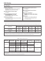
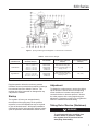
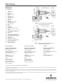
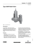
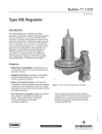
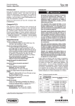
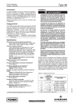
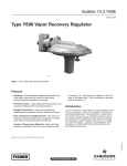
630 Series
Installation Guide
English – September 2009
This installation guide provides instructions for
installation, startup, and adjustment. To receive a copy
of the instruction manual, contact your local Sales
Office or view a copy at www.emersonprocess.com/
regulators. For further information refer to: 630 Series
Instruction Manual, form 1243, D100300X012.
Clean out all pipelines before installation of the
regulator and check to be sure the regulator has not
been damaged or has collected foreign material during
shipping. For NPT bodies, apply pipe compound to
the external pipe threads. Install the regulator in any
position desired, unless otherwise specified, but be
sure flow through the body is in the direction indicated
by the arrow on the body.
Installation
Vents
!
Warning
Only qualified personnel should install
or service a regulator. Regulators
should be installed, operated, and
maintained in accordance with
international and applicable codes and
regulations, and Emerson Process
Management Regulator Technologies,
Inc. instructions.
If the regulator vents fluid or a leak
develops in the system, it indicates that
service is required. Failure to take the
regulator out of service immediately may
create a hazardous condition.
Personal injury, equipment damage, or
leakage due to escaping fluid or bursting
of pressure-containing parts may result
if this regulator is overpressured or
is installed where service conditions
could exceed the limits given in the
Specifications section, or where
conditions exceed any ratings of the
adjacent piping or piping connections.
To avoid such injury or damage, provide
pressure-relieving or pressure-limiting
devices (as required by the appropriate
code, regulation, or standard) to prevent
service conditions from exceeding limits.
Additionally, physical damage to the
regulator could result in personal injury
and property damage due to escaping
fluid. To avoid such injury and damage,
install the regulator in a safe location.
!
Warning
When the unit is installed in an enclosed
area or indoors, escaping gas may
accumulate and be an explosion hazard.
Under these conditions the vent should
be piped away from the unit to a freely
ventilated outdoor location away from
air intakes, windows, etc. Protect all
vent openings against weather or the
entrance of any foreign material that
may plug the vent or affect operation of
the regulator or relief valve. Inspect all
vent openings periodically to be sure
they are not plugged. If the vent is in
an environment where freezing rain,
ice, or snow could clog the vent, it is
recommended that a weatherproof vent
be used.
Spring-loaded constructions have a screened vent
assembly (key 27) installed in the 1/4 NPT spring case
vent opening. If a remote vent is required, remove the
vent assembly and install a remote vent line.
Overpressure Protection
The recommended pressure limitations are stamped on
the regulator nameplate. Some type of overpressure
protection is needed if the actual inlet pressure
exceeds the maximum operating outlet pressure rating.
Overpressure protection should also be provided if the
regulator inlet pressure is greater than the safe working
pressure of the downstream equipment.
www.emersonprocess.com/regulators
D100300XUS2
Introduction
630 Series
Specifications
Available Configurations
Type 630: Spring-loaded reducing regulators
Type 630R: Spring-loaded relief valves
Maximum Allowable Outlet Pressures(1)
See Table 2
Maximum Allowable Pressure Drops(1)
See Table 1
Body Size and End Connection Style
1 or 2 NPT
Temperature Capabilities(1)
Standard: -20° to 150°F (-29° to 66°C)
Optional: -20° to 300°F (-29° to 149°C)
Maximum Allowable Inlet Pressures
Type 630 Regulators: See Table 1
Type 630R Relief Valves: See Table 3
(1)
Outlet Pressure Ranges(1)
3 to 500 psig (0,21 to 34,5 bar) with intermediate
values shown in Table 2
Orifice Sizes
1/8-inch (3,2 mm), 3/16-inch (4,8 mm),
1/4-inch (6,4 mm), 3/8-inch (9,5 mm),
or 1/2-inch (13 mm)
1. The pressure/temperature limits in this installation guide or any applicable standard limitation should not be exceeded.
Table 1. Maximum Allowable Inlet Pressures and Pressure Drops. Maximum inlet pressure not to exceed 1500 psig (103 bar).
Orifice Size, inchES (mm)
DISK MATERIAL
1/8 and 3/16
(3,2 and 4,8)
1/4 (6,4)
3/8 (9,5)
1/2 (13)
Nylon (PA) and Polytetrafluoroethylene (PTFE)
Nitrile(2) (NBR)
Fluorocarbon (FKM)
1500 (103)
600 (41,4)
200 (13,8)
1000 (69)
600 (41,4)
200 (13,8)
500 (34,5)
500 (34,5)
200 (13,8)
250 (17,2)
250 (17,2)
200 (13,8)
Maximum Allowable Inlet Pressure,
Psig (bar)
1500 (103)(1)
1500 (103)(1)
1000 (68,9)(1)
750 (51,8)(1)
1. Inlet pressure must not exceed the sum of the actual outlet pressure setting and the maximum allowable pressure drop. For example, with an outlet pressure setting of
200 psig (13,8 bar) and a 3/8-inch (9,5 mm) orifice with a maximum allowable pressure drop of 500 psi (34,5 bar, differential), the maximum allowable inlet pressure is 700 psig (48,3 bar).
2. Nitrile (NBR) valve disks are normally furnished for pressure drops to 200 psi (13,8 bar, differential). For better erosion resistance, Nylon (PA) valve disks are normally furnished for higher pressure
drops. Some erosion of valve disks occurs at all pressure drops due to solid particles in the flow stream. The rate of erosion is higher with large amounts of impurities in the flow stream and with
high-pressure drops. Valve disks and other regulator parts must be inspected periodically for erosion and damage and must be replaced as necessary.
Table 2. Maximum Outlet Pressures
Regulator
construction
Low-Pressure
High-Pressure
Outlet Pressure
Range, Psig (bar)
SPRING
Part Number
MAXIMUM OPERATING
OUTLET PRESSURE,
PSIG (bar)
Maximum Outlet
Pressure Over
SETPOINT(1), Psig (bar)
3 to 10 (0,21 to 0,69)
0W019227022
10 (0,69)
8 to 20 (0,55 to 1,4)
0W019127022
20 (1,4)
17 to 30 (1,2 to 2,1)
0W019027022
30 (2,1)
20(2) (1,4)
27 to 40 (1,9 to 2,8)
0Y0664000A2
40 (2,8)
Limited by Maximum
Emergency Outlet Pressure
27 to 50
46 to 95
90 to 150
150 to 200
200 to 275
(1,9 to 3,5)
(3,2 to 6,6)
(6,2 to 10,3)
(10,3 to 13,8)
(13,8 to 19,0)
0W019227022
0W019127022
0W019027022
0Y0664000A2
1J146927142
50
95
150
200
275
(3,5)
(6,6)
(10,3)
(13,8)
(19,0)
275 to 500 (19,0 to 34,5)
1K370927082
500 (34,5)
Maximum Emergency
Outlet (Casing)
Pressure(4), psig (bar)
20 (1,4)
200 (13,8)
45 (3,1)
550 (37,9)
200(3) (13,8)
1. Damage to internal parts of the regulator may occur if outlet pressure exceeds the actual pressure setting by amounts greater than those shown in this column.
2. For outlet pressure settings to 25 psig (1,7 bar) only. For pressure settings over 25 psig (1,7 bar), outlet pressure is limited by maximum emergency outlet pressure of 45 psig (3,1 bar).
3. For outlet pressure settings to 350 psig (24,2 bar) only. For pressure settings over 350 psig (24,2 bar), outlet pressure is limited by maximum emergency outlet pressure of
550 psig (37,9 bar).
4. Leakage or bursting of pressure containing parts may occur if outlet pressure exceeds these values.
2
630 Series
0X00119-F
Figure 1. Spring-Loaded Type 630 Regulator - Low-Pressure Construction
Table 3. Outlet Pressure Ranges
Regulator
construction
Relief (inlet) Pressure
Settings, Psig (bar)
Part Number
Maximum Allowable
Relief (Inlet) Pressure,
psig (bar)
Maximum Emergency
INlet (casing) Pressure(1),
Psig (bar)
Low-Pressure
3 to 8
6 to 17
15 to 22
20 to 35
27 to 50
(0,21 to 0,55)
(0,41 to 1,1)
(1,0 to 1,5)
(1,4 to 2,4)
(1,9 to 3,5)
0W019227022
0W019127022
0W019027022
0Y066427022
1J146927142
Relief Pressure Setting Plus
Maximum Allowable Build-up of
25 psig (1,7 bar)
75 (5,2)
High-Pressure
30 to 70
50 to 95
75 to 175
150 to 250
(2,0 to 4,8)
(3,5 to 6,5)
(5,2 to 12,1)
(10,4 to 17,3)
0W019127022
0W019027022
0Y066427022
1J146927142
Relief Pressure Setting Plus
Maximum Allowable Build-up of
250 psig (17 bar)
550 (38,0)
1. Leakage or bursting of pressure-containing parts may occur if inlet pressure exceeds these values.
Regular operation below the maximum pressure
limitations does not preclude the possibility of damage
from external sources or debris in the line. The
regulator should be inspected for damage after any
overpressure condition.
Startup
The regulator is factory set at approximately
the midpoint of the spring range or the pressure
requested, so an initial adjustment may be required
to give the desired results. With proper installation
completed and relief valves properly adjusted, slowly
open the upstream and downstream shutoff valves.
Adjustment
To change the outlet pressure, remove the closing
cap or loosen the locknut and turn the adjusting
screw clockwise to increase outlet pressure or
counterclockwise to decrease pressure. Monitor
the outlet pressure with a test gauge during the
adjustment. Replace the closing cap or tighten the
locknut to maintain the desired setting.
Taking Out of Service (Shutdown)
!
Warning
To avoid personal injury resulting from
sudden release of pressure, isolate
the regulator from all pressure before
attempting disassembly.
3
630 Series
Parts List
Key Description 1
2
3
4
5
6
7
8
9
10 11
12
13
14
15
16
17
18
19
20
21
21 22
23
27
31
32
33
34 35
36
37
52
53
Adjusting Screw
Hex Nut
Spring Case
Upper Spring Seat
Spring
Cap Screw
Lower Spring Seat
Diaphragm Plate
Cap Screw
Cap Screw
Diaphragm
Connector Head Assembly
Diaphragm Adaptor
Lever Assembly
Pin
Gasket
Cap Screw
Inlet Adaptor
Inlet Body Gasket (2 required)
Orifice
Valve Disk Assembly Type 630 only
O-Ring Holder (Type 630R only)
Valve Carrier
Body
Vent Assembly, Type Y602-12
Cap Screw (2 required) (not shown)
O-Ring Washer (Type 630R only)
Plug (not shown)
Nameplate
Drive Screw (4 required)
Machine Screw (Type 630R only)
O-Ring (Type 630R only)
NACE Tag (not shown)
Tag Wire (not shown)
CB2197-E
Figure 2. Spring Loaded Type 630 Regulator High-Pressure Construction
CD3355-E
Figure 3. Spring-Loaded Type 630R Relief Valve
High-Pressure Construction
Industrial Regulators
Natural Gas Technologies
TESCOM
Emerson Process Management
Regulator Technologies, Inc.
Emerson Process Management
Regulator Technologies, Inc.
Emerson Process Management
Tescom Corporation
USA - Headquarters
McKinney, Texas 75069-1872 USA
Tel: 1-800-558-5853
Outside U.S. 1-972-548-3574
USA - Headquarters
McKinney, Texas 75069-1872 USA
Tel: 1-800-558-5853
Outside U.S. 1-972-548-3574
USA - Headquarters
Elk River, Minnesota 55330-2445 USA
Tel: 1-763-241-3238
Asia-Pacific
Shanghai, China 201206
Tel: +86 21 2892 9000
Asia-Pacific
Singapore, Singapore 128461
Tel: +65 6777 8211
Europe
Bologna, Italy 40013
Tel: +39 051 4190611
Europe
Bologna, Italy 40013
Tel: +39 051 4190611
Gallardon, France 28320
Tel: +33 (0)2 37 33 47 00
Middle East and Africa
Dubai, United Arab Emirates
Tel: +971 4811 8100
Europe
Selmsdorf, Germany 23923
Tel: +49 (0) 38823 31 0
For further information visit www.emersonprocess.com/regulators
The Emerson logo is a trademark and service mark of Emerson Electric Co. All other marks are the property of their prospective owners. Fisher is a mark owned by Fisher Controls, Inc., a
business of Emerson Process Management.
The contents of this publication are presented for informational purposes only, and while every effort has been made to ensure their accuracy, they are not to be construed as warranties or
guarantees, express or implied, regarding the products or services described herein or their use or applicability. We reserve the right to modify or improve the designs or specifications of such
products at any time without notice.
Emerson Process Management does not assume responsibility for the selection, use or maintenance of any product. Responsibility for proper selection, use and maintenance of any Emerson
Process Management product remains solely with the purchaser.
©Emerson Process Management Regulator Technologies, Inc., 2005, 2009; All Rights Reserved