1
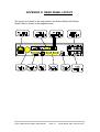
5SX_ LANlink
Router Option
User Manual
WARNING - BEFORE INSTALLATION, PLEASE
REFER TO SAFETY INSTRUCTIONS IN
APPENDIX A, AND EMC INSTRUCTIONS IN
APPENDIX C
Certified Compliant in the EC, when fitted in accordance with the installation
instructions, against the following directives/standards:
Low Voltage Directive (73/23/EEC and amendment 93/68/EEC)
EN60950
: 1992 (Safety)
Electromagnetic Compatibility
subsequent amendments to date):
EN55022
EN50082-1
directive
(89/336/EEC
and
: 1994 (Emissions)
: 1992 (Immunity)
directive
Telecommunications
Terminal
Equipment
(91/263/EEC and amendment 93/68/EEC) where indicated in
approvals requirements section.
Part Number: EA88001A
Echo LANlink Router Option User Manual
Issue 1.0
04 December 1997
Page 2 of 59
CONTENTS
1
INTRODUCTION.................................................................... 6
1.1
1.2
Functional Overview............................................................................. 7
Typical Applications ............................................................................. 7
2
USE AND CONFIGURATION................................................ 9
2.1
2.2
2.3
2.4
2.4.1
2.4.2
2.5
2.5.1
2.5.2
2.5.3
2.6
2.6.1
2.6.2
2.6.3
2.6.4
2.6.5
2.6.6
2.6.7
2.6.8
2.6.9
Router Configuration ............................................................................ 9
Supervisor Terminal Requirements ...................................................... 9
Router Terminal Display....................................................................... 9
Router Management ........................................................................... 11
General Keyboard Conventions .................................................. 11
Parameter Selection.................................................................... 11
Multiplexer Management .................................................................... 13
Allocating bandwidth to the Router ............................................. 13
Returning to the Main Menu Screen............................................ 14
Clearing the Configuration back to Factory Default .................... 14
System Status..................................................................................... 14
MAIN LINK CARRIER LOSS ....................................................... 15
D/I CARRIER LOSS .................................................................... 15
REMOTE ALARM........................................................................ 15
Nx64 CHANNEL x CONTROL DISAFFIRMED............................ 15
Nx64 CHANNEL x CLOCK FAIL ................................................. 15
MAIN LINK HIGH BIT ERROR RATE.......................................... 15
LOCAL/REMOTE MAP MISMATCH............................................ 15
D/I REMOTE ALARM .................................................................. 15
ROUTER WAN LINK STATUS.................................................... 16
3
INSTALLATION ................................................................... 17
3.1
3.2
3.3
3.4
3.5
3.6
3.7
3.7.1
3.7.2
Opening the Multiplexer ..................................................................... 17
Internal Link LK13 .............................................................................. 18
Installing the Router Option................................................................ 18
Testing................................................................................................ 19
Data Connections............................................................................... 19
Front Panel LEDs ............................................................................... 19
Quick Configuration............................................................................ 20
Multiplexer Configuration ............................................................ 20
Router Configuration ................................................................... 20
4
ROUTER MENU OPTIONS ................................................. 23
4.1
UNIT STATUS .................................................................................... 23
4.2
TRAFFIC ANALYSIS .......................................................................... 24
4.2.1
IP: ROUTING TABLE .................................................................. 24
4.2.2
IP: ARP TABLE ........................................................................... 25
4.2.3
IPX: RIP TABLE .......................................................................... 26
Echo LANlink Router Option User Manual
Issue 1.0
04 December 1997
Page 3 of 59
4.2.4
4.2.5
4.3
4.4
4.4.1
4.4.2
4.4.3
4.4.4
4.5
4.6
4.6.1
4.6.2
4.7
4.7.1
4.7.2
4.7.3
4.7.4
4.7.5
4.8
4.8.1
4.8.2
IPX: SAP TABLE ......................................................................... 27
SHOW TRAFFIC DETAILS ......................................................... 28
NETWORK LOADING ........................................................................ 28
REMOTE MANAGEMENT.................................................................. 29
TELNET OUT .............................................................................. 29
NAME SERVER CONFIGURATION............................................ 29
SECURITY .................................................................................. 30
SNMP SETUP ............................................................................. 31
UNIT CONFIGURATION .................................................................... 31
SERVICE SETUP ............................................................................... 32
ETHERNET SERVICE SETUP.................................................... 32
WAN SERVICE SETUP .............................................................. 34
FILTER SETUP .................................................................................. 36
MAC FILTERS (WAN or Ethernet) .............................................. 36
IP FILTER (WAN or Ethernet) ..................................................... 37
IPX SAP FILTER MENU (WAN or Ethernet) ............................... 38
IPX HEADER FILTERS ............................................................... 40
NOVELL KEEP-ALIVES .............................................................. 41
EVENTS ............................................................................................. 41
PPP EVENTS .............................................................................. 42
SYSTEM EVENTS....................................................................... 42
Appendix A WARNINGS............................................................. 44
Appendix B APPROVAL REQUIREMENTS .............................. 47
Appendix C EMC REQUIREMENTS .......................................... 48
Appendix D REAR PANEL LAYOUT ......................................... 49
Appendix E AUI PORT (15-WAY D-TYPE) PINOUT.................. 50
Appendix F 10BASE-T (RJ45) PORT PINOUT.......................... 51
Appendix G IP FILTER EXAMPLES........................................... 52
Appendix H IP SUBNETS ........................................................... 55
Appendix I
ROUTER MAINTENANCE MENU .......................... 56
Echo LANlink Router Option User Manual
Issue 1.0
04 December 1997
Page 4 of 59
GLOSSARY
ADPCM
ARP
ARPA
ASCII
BER
BOOTP
bps
CHAP
CRC
D&I
DNS
EEPROM
FAS
GND
ICMP
IP
IPX
LAN
LED
MAC
NCP
PABX
PAP
PC
PCM
PPP
RIP
SAP
SELV
SKT
SNMP
TCP
TDM
TFTP
UDP
WAN
Adaptive Differential Pulse-Code Modulation
Address Resolution Protocol
Advanced Research Projects Agency
American Standard Code for Information Interchange
Bit Error Rate
Bootstrap Protocol
bits per second
Challenge Handshake Authentication Protocol
Cyclic Redundancy Check
Drop and Insert
Domain Name Server
Electrically Erasable Programmable Read-Only Memory
Frame Alignment Synchronisation
Ground
Internet Control Message Protocol
Internet Protocol
Internetwork Packet Exchange
Local Area Network
Light Emitting Diode
Media Access Control
NetWare Core Protocol
Private Automatic Branch Exchange
Password Authentication Protocol
Personal Computer
Pulse Code Modulation
Point to Point Protocol
Routing Information Protocol
Server Advertising Protocol
Safety Extra Low Voltage
Socket
Simple Network Management Protocol
Transmission Control Protocol
Time Division Multiplexer
Trivial File Transfer Protocol
User Datagram Protocol
Wide Area Network
Echo LANlink Router Option User Manual
Issue 1.0
04 December 1997
Page 5 of 59
Echo LANlink
Router Option
User Manual
1 INTRODUCTION
This user manual describes installation, configuration and operation of the
Echo LANlink Multiplexer Router option, and must be referred to in
conjunction with the Echo LANlink Multiplexer User Manual.
The Echo LANlink is an E1 time division multiplexer (TDM) operating at
2Mbps compliant with both EUROPEAN and UK G.703 communications
standards. The Router Option card adds the capability of connecting two
Local Area Networks (LANs), via the E1 communication link, using some or
all of the link bandwidth.
A Router Option card needs to be installed inside the Echo LANlink at both
ends of the communications link. Each Router examines addressing
information on each LAN, and on recognition of an address on the distant
LAN, forwards the frame via the communication link, thereby linking the two
LANs together (see Figure 1).
Figure 1
Linking two LANs together
Echo LANlink Router Option User Manual
Issue 1.0
04 December 1997
Page 6 of 59
The Router Option card is easily configured using the management terminal
connected to the Echo LANlink from either end of the link, or through Telnet
at a relevant workstation either LAN.
1.1 Functional Overview
The Router Option card supports both transceiver connection (AUI port) and
hub (10BASE-T port) connection to a 10MHz Ethernet LAN. Ethernet frames
are transported to/from the remote LAN using some or all of the main
communications link bandwidth. The bandwidth is allocated in 64Kbps
timeslots amongst the various functions of the multiplexer as required by the
user. Up to 1984Kbps free bandwidth is available on an E1 link, 64Kbps is
permanently assigned for E1 frame synchronisation and signalling.
The router supports both the popular Internet Protocol (IP) and Internetwork
Packet Exchange (IPX) protocols. Many other protocols may be used
encapsulated by these as required: e.g. TCP, UDP, and NetWare.
The router maintains dynamic routing tables so that Ethernet frames are
routed to their correct destination. This capability is performed automatically
by the router as it “learns” routes and addresses available in the network. The
router will also broadcast its own routing information to other devices on the
network. Inoperative routes will time-out and be removed from the routing
tables so that alternative routes may be used in the event a communications
circuit failure.
A data compression algorithm is used when transporting Ethernet frames
through the communications link to increase the throughput of data.
Comprehensive filtering options are available so the router may act as a
sophisticated firewall to give added security for the LAN.
1.2 Typical Applications
The simplest application for the Router Option is to link two LANs as shown in
Figure 1. In this example, the Branch Office is linked to the Headquarters via
the Echo LANlinks and users at the Branch office will be able to access the
General Servers as if they were on the same network.
Further use of the router functionality can give sophisticated security for
network elements. Restrictive firewalls are easily built using subnet masking.
Entire subnets can be isolated from the network by simply entering
appropriate configurations – see Figure 2. In this example the Salesperson in
Echo LANlink Router Option User Manual
Issue 1.0
04 December 1997
Page 7 of 59
the Branch Office could access the Headquarters General Server via the
Echo LANlink, but accesses to the Finance Server could be stopped using
subnet masking in the Echo LANlink.
Figure 2
Restrictive Firewall Example
In addition to the features of the router, all the existing functions of the Echo
LANlink are still available. This means that as well as connecting two remote
LANs, the Echo LANlink can also carry PABX voice traffic (using D&I option
card or ADPCM option card), and data traffic between the two sites, all
simultaneously multiplexed onto one E1 communication link.
Echo LANlink Router Option User Manual
Issue 1.0
04 December 1997
Page 8 of 59
2 USE AND CONFIGURATION
This section covers connection and set-up of the Echo LANlink Router
Option, and must be used in conjunction with the Echo LANlink User Manual.
If you are not familiar with the general configuration procedure for the Echo
LANlink, please refer to that manual before reading further and attempting to
configure the Router Option.
2.1 Router Configuration
The Router is initially configured using an asynchronous terminal, or PC
using a suitable terminal emulation package such as Windows Terminal. The
terminal should be connected via its serial port to the SUPERVISOR port on
the rear of the Echo LANlink (see Echo LANlink User Manual).
2.2 Supervisor Terminal Requirements
The terminal should be configured as follows:
8 bit character, no parity, one stop bit, speed 9.6Kbps,
2.3 Router Terminal Display
After power up, the terminal will display the following message:
login:
Either type in the factory default login, mgr, or your login name if one has
previously been set and press <return>. The system will also prompt for a
password if one has been set - initially no password is required, but password
protection of the router configuration system is imperative to reduce the risk
of unauthorized changes. The set-up of a password is covered later.
The terminal will then display the following question.
Default terminal VT 100/220/320/420. OK (y or n)?
Echo LANlink Router Option User Manual
Issue 1.0
04 December 1997
Page 9 of 59
If you are using a terminal from this list type y <return>, or alternatively press
n <return> to enter another type: supported terminal types are shown in
Figure 3 - type one of them in to select a suitable terminal type and press
<return>
VT100
VT220
VT320
VT420
FALCO
Figure 3
SUNVIEW
SUN
WYSE50
A210
TVI925
TVI910
Supported Terminal Types
Once a terminal type has been selected, the main menu screen shown in
Figure 4 will be displayed. Using the keyboard arrow keys you should be able
to move the highlighted cursor between the various menu items. If this is not
the case, or the display is corrupted, it may be because the terminal type is
incorrect, or the terminal settings are wrong. In this case, pressing L followed
by <return> should lead you back to the login prompt.
+-------------------------------------------------------------------------------+
| UNIT: S1234
LOGOUT |
+-------------------------------------------------------------------------------+
ROUTER MANAGEMENT
MULTIPLEXER MANAGEMENT
NONE
SYSTEM STATUS
NO ALARMS
Figure 4
Main Menu Screen
The Echo LANlink with Router Option is configured in two parts: Router
Management (for all the router functions) and Multiplexer Management (for all
the multiplexer functions).
Echo LANlink Router Option User Manual
Issue 1.0
04 December 1997 Page 10 of 59
2.4 Router Management
Selecting ROUTER MANAGEMENT from the main menu allows the user to
configure the router. The router management screen is shown in Figure 5.
Refer to Section 4 for details on each menu option.
+-------------------------------------------------------------------------------+
| ROUTER: S1234
EXIT |
+-------------------------------------------------------------------------------+
UNIT STATUS
TRAFFIC ANALYSIS
NETWORK LOADING
REMOTE MANAGEMENT
UNIT CONFIGURATION
SERVICE SETUP
FILTER SETUP
EVENTS
Figure 5
Router Management Screen
2.4.1 General Keyboard Conventions
The following keys are used to navigate the configuration screens for the
router management.
Æ
Å
Ç
È
Moves the cursor block to the right
Moves the cursor block to the left
Moves the cursor block upwards
Moves the cursor block downwards
<return>
selects/initiates the highlighted option
2.4.2 Parameter Selection
When a command is selected from the command line using the cursor,
pressing <return> will initiate action.
Some commands require the user to enter data. In Figure 6, a user has
selected to ADD a new WAN IP filter. A new line has appeared allowing the
user to enter the source IP address for the WAN filter. In this case, type in the
required value using the keyboard and press <return>. Press <esc> to
cancel any data entry operation
Echo LANlink Router Option User Manual
Issue 1.0
04 December 1997 Page 11 of 59
+-------------------------------------------------------------------------------+
| WAN IP FILTER 1 - WAN IP FILTER 1: S1234
EXIT |
| ADD EDIT DELETE CLEAR NAME
|
+-------------------------------------------------------------------------------+
ENTER THE SOURCE I.P. ADDRESS (RETURN = ALL):
LINE SRC ADDR
SRC MASK
DEST ADD
DEST MASK
PROT S.PRT D.PRT RSLT
Figure 6
Entering a Parameter
Echo LANlink Router Option User Manual
Issue 1.0
04 December 1997 Page 12 of 59
2.5 Multiplexer Management
Selecting MULTIPLEXER MANAGEMENT from the main menu allows the
user to configure the multiplexer functions. If another user is currently
accessing the multiplexer management page (e.g. via a Telnet session) this
will be indicated next to the menu item. Only one session is allowed access to
the multiplexer functions at any one time. If NONE is displayed the user is
free to enter multiplexer management. If an IP address is displayed, then this
is the address of the user currently accessing the multiplexer functions. If
CONSOLE is displayed, then the multiplexer functions are being accessed
via the multiplexer supervisor port. You may choose to break their session if
absolutely necessary but this should be used with caution.
Figure 7 shows the main multiplexer configuration page. Refer to the Echo
LANlink User manual for details on how to configure the multiplexer. New
options that are available when the Router Option is fitted are detailed below.
2 MEGABIT E1 MULTIPLEXER
V1.04
================================ 00:00 25/12/97 ===============================
Main Link (UK)
: SYNCHRONISED
Exit to Router:
Mode
: NORMAL
* Nx64 Channels : 2 + ROUTER
Framing
: CRC4
D&I Channels : NOT FITTED
Idle Bandwidth
: 1984K
Alarms
: None
Clock Reference : INTERNAL
Statistics
: Main Link
Configuration
:>LOCAL
Events
: Log
Nx64 Channel
:
1
2
ROUTER
Rate
: OFF
OFF
OFF
Mode
: NORMAL
NORMAL
Tx Clock
: INT
INT
Rx Clock
: INT
INT
Indicate
: ON
ON
Control
: ON
ON
------------------------TIMESLOT MAP--------------------------0 0 0 0 0 0 0 0 0 0 1 1 1 1 1 1 1 1 1 1 2 2 2 2 2 2 2 2 2 2 3 3
0 1 2 3 4 5 6 7 8 9 0 1 2 3 4 5 6 7 8 9 0 1 2 3 4 5 6 7 8 9 0 1
--------------------------------------------------------------S - - - - - - - - - - - - - - - - - - - - - - - - - - - - - - Cursor keys to move, CTRL-U to save, ESC to abandon
===============================================================================
Use <SPACEBAR>/<+>/<-> to select
Figure 7
Main Multiplexer Configuration Page
2.5.1 Allocating bandwidth to the Router
The amount of bandwidth allocated to the router determines the throughput of
Ethernet data through the router. Bandwidth is allocated using the timeslot
map on the multiplexer Nx64 Channels page. Typing ‘R’ in the timeslot map
will assign that timeslot to the router. Any combination of timeslots may be
allocated to the router (except timeslot 0, which is always reserved) and each
timeslot assigned will contribute 64Kbps of bandwidth. The Rate field for the
router will automatically be updated to show the bandwidth assigned.
Echo LANlink Router Option User Manual
Issue 1.0
04 December 1997 Page 13 of 59
Figure 8 shows an example timeslot set-up with 512Kbps allocated to channel 1,
320Kbps allocated to channel 2, and 1152Kbps allocated to the router.
2 MEGABIT E1 MULTIPLEXER
V1.04
================================ 00:00 25/12/97 ===============================
Main Link (UK)
: SYNCHRONISED
Exit to Router:
Mode
: NORMAL
* Nx64 Channels : 2 + ROUTER
Framing
: CRC4
D&I Channels : NOT FITTED
Idle Bandwidth
: 0K
Alarms
: None
Clock Reference : INTERNAL
Statistics
: Main Link
Configuration
:>LOCAL
Events
: Log
Nx64 Channel
:
1
2
ROUTER
Rate
: 512K
320K
1152K
Mode
: NORMAL
NORMAL
Tx Clock
: INT
INT
Rx Clock
: INT
INT
Indicate
: ON
ON
Control
: ON
ON
------------------------TIMESLOT MAP--------------------------0 0 0 0 0 0 0 0 0 0 1 1 1 1 1 1 1 1 1 1 2 2 2 2 2 2 2 2 2 2 3 3
0 1 2 3 4 5 6 7 8 9 0 1 2 3 4 5 6 7 8 9 0 1 2 3 4 5 6 7 8 9 0 1
--------------------------------------------------------------S R 1 R 1 R R 2 2 R R R R R R R R R R R 1 1 1 1 1 1 R R R 2 2 2
Cursor keys to move, CTRL-U to save, ESC to abandon
===============================================================================
Use <SPACEBAR>/<+>/<-> to select
Figure 8
Example Timeslot Set-up
2.5.2 Returning to the Main Menu Screen
Selecting the Exit to Router menu option will return the user back to the
main menu screen. If any unsaved changes have been left, a prompt will
appear to confirm the action, as any unsaved changes will be lost after
leaving the multiplexer management page.
2.5.3 Clearing the Configuration back to Factory Default
The multiplexer may be reset back to the factory default configuration by
pressing CTRL-R four times when the cursor is on the Configuration item. A
confirm message will be displayed before the configuration is reset. The
previous configuration will be lost.
2.6 System Status
The main menu SYSTEM STATUS item displays the alarm status of the
overall system. Selecting this item gives the status of all the alarms in the
system as detailed below. Note the router monitors the alarm status of the
multiplexer and therefore the alarms have to be configured under multiplexer
management to be valid.
Echo LANlink Router Option User Manual
Issue 1.0
04 December 1997 Page 14 of 59
2.6.1 MAIN LINK CARRIER LOSS
The local Multiplexer cannot identify a valid synchronisation sequence (FAS,
CRC4 etc) from the remote multiplexer.
2.6.2 D/I CARRIER LOSS
The Multiplexer cannot identify a valid synchronisation sequence (FAS,
CRC4 etc) from the unit attached to the D&I port.
2.6.3 REMOTE ALARM
The unit attached to the D&I port is generating an alarm in the framing
information, that is, it is reporting that it has a problem.
2.6.4 Nx64 CHANNEL x CONTROL DISAFFIRMED
One of the channel ports (which is in use) is not providing the multiplexer with
a true CONTROL signal. This may mean that the signals have not been
connected at all. Note that unconnected CONTROL inputs will produce a
random ON or OFF indication. Control inputs from ports that are not
allocated in the timeslot map are ignored.
2.6.5 Nx64 CHANNEL x CLOCK FAIL
One of the data channels cannot synchronise its clock to the global network
clock. This may occur if a channel is set to external clock, and either no
clock at all is connected, or the clock that is connected is the wrong rate.
2.6.6 MAIN LINK HIGH BIT ERROR RATE
Shows FAULT if the Bit Error Rate exceeds the threshold set. With an error
free link, this fault will eventually clear when the BER becomes less than the
threshold set.
2.6.7 LOCAL/REMOTE MAP MISMATCH
The configuration in the local unit does not match that in the remote unit.
This would almost certainly lead to data errors on some channels.
2.6.8 D/I REMOTE ALARM
The unit attached to the D&I port is generating an alarm in the framing
information, that is, it is reporting that it has a problem.
Echo LANlink Router Option User Manual
Issue 1.0
04 December 1997 Page 15 of 59
2.6.9 ROUTER WAN LINK STATUS
The status of the link between the two routers is displayed.
Echo LANlink Router Option User Manual
Issue 1.0
04 December 1997 Page 16 of 59
3 INSTALLATION
WARNING – Refer to Appendix A for Safety Instructions.
WARNING - The multiplexer must be disconnected from the power supply
and all peripheral connections before opening.
3.1 Opening the Multiplexer
With the power cord and all peripherals DISCONNECTED, the screws on the left,
right and top of the multiplexer are removed using a Pozidrive screwdriver to gain
access to the interior of the multiplexer. This allows installation of the option
cards
J15
J10
Figure 9
LK13
Echo LANlink Baseboard
Echo LANlink Router Option User Manual
Issue 1.0
04 December 1997 Page 17 of 59
3.2 Internal Link LK13
Locate the internal connector LK13 on the motherboard (refer to Figure 9). This
will be fitted with shorting links if the Echo LANlink was supplied without the
Router Option. Remove the shorting links before fitting the Router Option. The
links may be repositioned on one pin for storage.
3.3 Installing the Router Option
Remove the option blanking plate above the CH 1 and CH2 connectors on the
rear panel of the multiplexer. The blanking plate may be discarded if not required.
The Router Option card should be carefully fitted in the position shown in Figure
10, connecting to J10 and J15 on the motherboard (refer to Figure 9). The Router
Option power connector (flying lead) should be connected to J12 (ensure correct
polarisation). Refit the rear panel screws to secure the option card
Router
Option
Figure 10
J12
Echo LANlink showing Router Option Fitted
Echo LANlink Router Option User Manual
Issue 1.0
04 December 1997 Page 18 of 59
3.4 Testing
Replace the cover and screws before powering up the unit. Correct
installation of the Router Option may be confirmed by the login prompt (see
section 2.3) appearing on the terminal screen. If the red error LED on the
front panel is on, this indicates hardware fault has occurred. In this case,
disconnect the power cable and check the installation of the Router Option is
correct.
3.5 Data Connections
The Ethernet connection is made using either the AUI (15-way D-type – see
Appendix E) or 10BASE-T (RJ45 see Appendix F) port at the rear of the unit
(refer to Appendix D).
3.6 Front Panel LEDs
For information regarding CARRIER, MAJOR ALARM, MINOR ALARM and
LOOP, refer to the Echo LANlink User Manual.
LED Label
Notes
TX DATA
Flashes when unit is transmitting Ethernet data
RX DATA
Flashes when unit is receiving Ethernet data
COLLISION
Flashes if an Ethernet collision is detected
FAULT
RED if a power up hardware fault has occurred
Echo LANlink Router Option User Manual
Issue 1.0
04 December 1997 Page 19 of 59
3.7 Quick Configuration
The first stage in configuration is to allocate some bandwidth of the
communication link to the router. The second stage is to configure the
SERVICE SETUP to allow communication between the two routers.
3.7.1 Multiplexer Configuration
From the main menu enter MULTIPLEXER MANAGEMENT. Allocate
bandwidth to the router by entering ‘R’ in any free timeslot positions near the
bottom of the screen. Each timeslot allocated will contribute 64Kbps of
bandwidth to the router.
Save the multiplexer configuration using CTRL-U.
Leave MULTIPLEXER MANAGEMENT by selecting Exit to Router at the top
right of the screen.
3.7.2 Router Configuration
From the main menu enter ROUTER MANAGEMENT. Go into SERVICE
SETUP and enter ETHERNET SERVICE. The following parameters need to
be set. N.B. IP service must be configured even when IP is not being used on
the local Ethernet network.
3.7.2.1
Service Name
A name to identify the local Ethernet Network, this is displayed in the IP RIP,
IPX RIP and IPX SAP tables and should ideally refer to network location.
3.7.2.2
IP Address
A unique address within the IP network connected to the local Ethernet port.
This is the IP Address of the Router and is used as the gateway address for
routing between the local Ethernet network and the WAN link.
3.7.2.3
IP Subnet Bits
The Subnet Bits should be set if subnetting is to be used on the local
network, otherwise the default 0 should be used.
Echo LANlink Router Option User Manual
Issue 1.0
04 December 1997 Page 20 of 59
3.7.2.4
Receive IP RIP
To enable routes to destinations within the local network to be added to the
routing table this field should be set to the appropriate protocol; NONE, RIP1,
RIP2 or both RIP1 and RIP2. If the RIP version is unknown then set BOTH.
3.7.2.5
Transmit IP RIP
To allow the Router to propagate routes learnt from the WAN to the local
network, this field must be set to the correct value for the RIP protocol being
used or to NONE to disable RIP transmission. Available options include
NONE, RIP1, RIP1 compatible or RIP2.
3.7.2.6
IP Broadcast
This field enables the IP broadcast bits to be set to either all ones or all
zeroes depending on the requirements of the local Ethernet equipment.
Normally this would be set to All Ones.
3.7.2.7
IP Filter
The IP Filter is used to prevent specific IP packets being transmitted over the
WAN link. The Filter Table is defined in the Static Routes and Filter Setup
Menu.
For initial configuration this field should be left set to NO until the Filter Table
entries are defined. Set to YES, the default action of an empty Filter Table is
to block all IP transmissions.
3.7.2.8
IPX Configuration
If IPX (Internetworking Protocol Exchange) is not being used then these fields
can be left at their default values to disable.
3.7.2.9
IPX Network Number
If there is no file server on the local Ethernet then the network number must
be specified. If a local file server is present the Network Number can be left
set to zero, and the Router will auto-sense the number when connected.
3.7.2.10 IPX Frame Types
The default frame type is Ethernet 802.3. If 802.2 is required this setting can
be changed.
Echo LANlink Router Option User Manual
Issue 1.0
04 December 1997 Page 21 of 59
3.7.2.11 Receive IPX RIP
Set this field to YES to receive IPX RIP responses from other routers or
servers on the local network.
3.7.2.12 Transmit IPX RIP
Set this field to YES to transmit regular IPX RIP responses to other routers or
servers on the local network. If set to NO, IPX RIP responses will only be
sent as a result of receiving a RIP request.
3.7.2.13 Receive IPX SAP
Set this field to YES if you wish to receive IPX SAP responses from other
routers or servers on the local network. Requests are still received and
replied to.
3.7.2.14 Transmit IPX SAP
Set to YES to allow transmission of regular IPX SAP responses to other
routers or servers on the local network. If set to NO, IPX SAP responses will
only be sent as a result of receiving a SAP request.
3.7.2.15 IPX SAP Filter
The IPX SAP Filter is used to remove unwanted server entries from the SAP
table and their propagation to the WAN link. If no filter table entries have
been created and this option is set to YES, the default action is to ignore all
SAP entries.
Once configuration is complete, move the cursor to the EXIT position and
press <return>.
Echo LANlink Router Option User Manual
Issue 1.0
04 December 1997 Page 22 of 59
4 ROUTER MENU OPTIONS
The menu options allow the user to configure the router to individual
requirements. The menu tree is shown in the diagram below, and each
option is discussed in the following section.
Login Prompt
Router
Management
Unit Status
Traffic
Analysis
Multiplexer
Management
Network
Loading
Remote
Management
Unit
Configuration
System
Status
Service
Setup
Filter
Setup
Events
4.1 UNIT STATUS
This option displays statistics for the Ethernet and WAN links. At the top of
the screen the unit name and time since power on are displayed.
The user can use the CLEAR option to reset the data counts to begin new
analysis or EXIT option to leave the page.
The following table describes the parameters that are displayed:
PARAMETER
NAME
STATE
DESCRIPTION
OPTIONS
Ethernet segment name User defined
WAN service name
Port status for the ACTIVE
Ethernet Interface
FILTER
Service status for WAN LINK DOWN
Interfaces
COMPRESSED
IP MODE
IPX MODE
Current WAN IP routing ROUTE
status
BLOCK
BRIDGE
Current
WAN
IPX ROUTE
routing status
BLOCK
BRIDGE
Echo LANlink Router Option User Manual
Issue 1.0
04 December 1997 Page 23 of 59
PARAMETER
OTHER MODE
Rx PACKET COUNT
Rx PACKET ERROR
Tx PACKET COUNT
Tx PACKET
OVERFLOW
LINE SPEED
DESCRIPTION
OPTIONS
Current
OTHER BLOCK
protocol routing status
BRIDGE
Number of packets seen
on
the
segment
connected to the port
displayed.
Number
of
packets
received with CRC or
Frame errors.
Number
of
packets
transmitted by Router.
Number
of
packets
discarded by Router
owing to queue time
exceeding the permitted
maximum delay.
Indicates the amount of
bandwidth
(in
bps)
allocated to the router
by the multiplexer
4.2 TRAFFIC ANALYSIS
Menu options available from the Traffic Analysis selection are detailed below.
4.2.1 IP: ROUTING TABLE
This table displays the current IP routes in the routing table. Information in
this table comes from four sources:
1.
2.
3.
4.
The IP address of the router determines which network is physically
connected to the Ethernet Port.
RIP Packets received from the Ethernet Port.
RIP Packets received from the WAN port.
Static (permanent) entries entered by the user.
The user can define up to 16 static routes in this table. The simplest means
to allow the router to 'learn' network routes is to use IP RIP Receive. For
configuration see the Ethernet Service Setup section. The user can then
highlight all routes to be made static using the cursor and press <return>.
The user will be prompted to either delete the entry or make it part of the
Echo LANlink Router Option User Manual
Issue 1.0
04 December 1997 Page 24 of 59
routing table. Turning off IP RIP Receive as before will cause other learned
routes to age out after about four minutes.
PARAMETER
NETWORK
SUBNET BITS/MASK
GATEWAY
SERVICE
TIMER
METRIC
DESCRIPTION
The IP Network number to which this
RIP entry relates.
This shows the subnet mask detected
by the Router.
The IP Address of the next gateway
used in this route to send a packet to
the specified network.
The required service that must be
used to reach a specified network.
This will display the time interval in
seconds, since
this routing entry
was last updated. For the attached
Network this will be left blank. For
static IP Routes this will be STATIC.
This will indicate the number of
nodes passed in the route to the
Network.
RIP packets pass on a
value that is incremented at each
node.
The metric is used for
selecting the best route if a multiple
route network exists.
4.2.2 IP: ARP TABLE
This table gives the current ARP table for the router.
PARAMETER
IP ADDRESS
MAC ADDRESS
TIMER
Echo LANlink Router Option User Manual
DESCRIPTION
The IP Network number to which this
entry relates.
The
MAC
Address
(Ethernet
Address) associated with an IP
address.
If no MAC address is
available “NONE” will be displayed.
Displays the time interval in seconds
since a routing entry was last
updated. For the attached Network
this will be left blank.
Issue 1.0
04 December 1997 Page 25 of 59
4.2.3 IPX: RIP TABLE
This table displays the current IPX routes in the IPX RIP table. Information in
this table comes from four sources:
1. The IPX network number determines which network is physically attached
to the Ethernet port.
2. IPX SAP Packets received from the Ethernet Port.
3. IPX SAP Packets received from the WAN port.
4. Static (permanent) entries entered by the user.
The user can define up to 16 static routes in this table. The simplest means
to allow the router to 'learn' available services is to use IPX RIP Receive. For
configuration see the Ethernet Service Setup section. The user can then
highlight all routes to be made static using the cursor and press <return>.
The user will be prompted to either delete the entry or make it part of the IPX
RIP table. Turning off IPX RIP Receive as before will cause other learned
services to age out after about four minutes.
PARAMETER
IPX NETWORK
SERVICE
NODE
HOPS
TICKS
TIMER
Echo LANlink Router Option User Manual
DESCRIPTION
The IPX Network number to which
this entry relates.
The service that must be used to
reach a specified Network.
This is the Ethernet address of the
next node on the route to the
Network.
This indicates the number of hops on
the preferred route to the Network.
This gives the delay in ticks (18
ticks/second) to be expected when
communicating with the Network.
This will display the time in seconds
since the routing entry was last
updated. For the attached Network
this will be left blank.
Issue 1.0
04 December 1997 Page 26 of 59
4.2.4 IPX: SAP TABLE
This table displays the IPX services in the IPX SAP table. Information in this
table comes from three sources:
1. IPX SAP Packets received from the Ethernet Port.
2. IPX SAP Packets received from the WAN port.
3. Static entries entered by the user.
The user can define up to 16 static routes in this table. The simplest means
to allow the router to 'learn' available services is to use IPX SAP Receive.
For configuration see the Ethernet Service Setup section. The user can then
highlight all services to be made static using the cursor and press <return>.
The user will be prompted to either delete the entry or make it part of the IPX
SAP table. Turning off IPX SAP Receive as before will cause other learned
services to age out after about four minutes.
PARAMETER
TYPE
NETWORK
SERVICE
NODE
SOCKET
HOPS
TIMER
NAME
Echo LANlink Router Option User Manual
DESCRIPTION
Server identification number, defined
by IPX e.g. file server: 4, print server:
47.
Server network number.
The service that must be used to
reach a specified Network.
Server node address.
Node address socket number used to
access the server.
Number of hops in the preferred route
to this server.
Time interval in seconds, since this
routing entry was last updated. For
the attached Network, this will be left
blank.
This will display the time in seconds
since the routing entry was last
updated. For the attached Network
this will be left blank.
Issue 1.0
04 December 1997 Page 27 of 59
4.2.5 SHOW TRAFFIC DETAILS
Displays a list of the current traffic received by the router.
PARAMETER
ADDRESS
AGE
FLAGS
DESCRIPTION
MAC address
Time since packet last received
L = local to the attached LAN
H = addressed to this unit
4.3 NETWORK LOADING
This option shows the load on the WAN and Ethernet ports over five second,
one minute and five minute periods.
PARAMETER
AVERAGE PACKETS
PEAK PACKETS
AVERAGE BANDWIDTH
PEAK BANDWIDTH
Echo LANlink Router Option User Manual
DESCRIPTION
The average number of packets seen
by the Router on a per second basis
over the displayed time period at that
port.
The peak number of packets seen by
the Router on a per second basis
over the displayed time period.
The average percentage of available
bandwidth used by the segment or
serial link attached to that port on a
per second basis over the selected
time period.
The peak percentage of available
bandwidth used by the segment or
serial link attached to that port on a
per second basis over the selected
time period.
Issue 1.0
04 December 1997 Page 28 of 59
4.4 REMOTE MANAGEMENT
Selecting the Remote Management menu presents the user with the following
four options.
Unit Status
Traffic
Analysis
Network
Loading
Remote
Management
Telnet Out
Name Server
Configuration
Security
SNMP
Security
Unit
Configuration
Service
Setup
Filter
Setup
Events
View Name to
IP Cache
4.4.1 TELNET OUT
This option will enable telnet connection, by entering the relevant IP Address,
to a remote workstation.
4.4.2 NAME SERVER CONFIGURATION
This menu allows the user to configure the Router DNS Client features.
PARAMETER
TYPE
DESCRIPTION
The type of name server in use.
OPTIONS
NONE
DNS
SERVER
IP The IP address of the name User defined
ADDRESS
server.
IP TO NAME Type of mapping between REVERSE MAPPING
MAPPING
addresses and names. Some IN-ADDR.ARPA DOMAIN
servers allow address entry to get
names, in addition to entering
names to get addresses (reverse
mapping.)
NAME TO IP If an address is requested from Go to Name to IP Cache
CACHE
the DNS server the Router Table
caches the map. This map can
therefore be viewed.
Echo LANlink Router Option User Manual
Issue 1.0
04 December 1997 Page 29 of 59
4.4.2.1
NAME TO IP CACHE
PARAMETER
IP ADDRESS
NAME
TIMER
DESCRIPTION
The name server IP address.
The name associated to this IP address.
If a name request is made to the DNS it will allocate a
time period to retain the information. The timer shows
how much time remains.
4.4.3 SECURITY
PARAMETER
CHANGE
USER
PASSWORD
DESCRIPTION
Allows user to change
password.
Old
password
must
be
entered
prior
to
acceptance.
OPTIONS
USER
PASSWORD
User password access
control.
ENABLE
USER
CHANGE
OWN PASSWORD
User password change
access control
ENABLE
USER LOGIN
User access control
ENABLE
DISABLE
DISABLE
DISABLE
USER
TELNET
LOGIN FROM
Telnet access control
NONE
ANY
IP ADDRESS
IP NAME
CHANGE
MANAGER
PASSWORD
Factory
SYSTEM.
MANAGER
PASSWORD
Manager
password
access control
ENABLE
MANAGER
TELNET
LOGIN
FROM
Restricts Telnet access
to
the
Router
management to the
following. Up to four IP
names/addresses can
be used.
NONE
Echo LANlink Router Option User Manual
pre-set:
Issue 1.0
ENTER NEW
DISABLE
ANY
IP ADDRESS
IP NAME
04 December 1997 Page 30 of 59
PARAMETER
READ
CONFIGURATION
FROM
DESCRIPTION
Access permission to
read configuration from
the
Router
from
external source.
OPTIONS
NONE
ANY
IP ADDRESS
IP NAME
EXTERNAL
LOGIN
UNIT
External
control
unit
access
ENABLE
DISABLE
4.4.4 SNMP SETUP
PARAMETER
COMMUNITY
CONTACT NAME
EQUIPMENT LOCATION
SEND SNMP TRAPS TO
DESCRIPTION
SNMP Community: default PUBLIC
Responsible for equipment. Useful to
give telephone number.
Allows rapid location of equipment
when required.
IP addresses of four SNMP stations.
4.5 UNIT CONFIGURATION
PARAMETER
ROUTER NAME
ETHERNET ADDRESS
UNIT SERIAL NUMBER
SOFTWARE REVISION
DEFAULT TERMINAL
Echo LANlink Router Option User Manual
DESCRIPTION
User defined identification.
Unique Ethernet address.
Fixed serial number for Router
option.
Router software version/date.
Default terminal type for access.
Issue 1.0
04 December 1997 Page 31 of 59
4.6 SERVICE SETUP
Unit Status
Traffic
Analysis
Network
Loading
Remote
Management
Unit
Configuration
Ethernet
Service
Service
Setup
Filter
Setup
Events
WAN Service
PPP Setup
PARAMETER
ETHERNET SERVICE
DESCRIPTION
Brief summary of the LAN service
available, including IP and IPX
addresses as appropriate.
Summary of traffic filters in use on
WAN link.
WAN SERVICE
4.6.1 ETHERNET SERVICE SETUP
PARAMETER
SERVICE NAME
IP ADDRESS
IP SUBNET BITS
RECEIVE IP RIP
TRANSMIT IP RIP
DESCRIPTION
User defined name for
the
local
Ethernet
network
IP Address of the
Router Ethernet Port.
The number of subnet
bits and subnet masks
corresponding to this IP
Address.
Defines the type of RIP
Packets received on the
Ethernet Interface.
OPTIONS
NONE
RIP 1 ONLY
RIP 2 ONLY
BOTH
Defines the type of RIP NONE
Packets
used
to RIP 1 ONLY
transmit
Routing RIP 1 COMP
information
RIP 2 ONLY
BOTH
Echo LANlink Router Option User Manual
Issue 1.0
04 December 1997 Page 32 of 59
PARAMETER
IP BROADCAST
IP FILTER
MAC FILTER
IPX NETWORK
IPX FRAME
RECEIVE IPX RIP
TRANSMIT IPX RIP
RECEIVE IPX SAP
TRANSMIT IPX SAP
IPX SAP FILTER
DESCRIPTION
IP Broadcast Packet
structure
Enable or disable the IP
Filter Table defined for
the Ethernet port. N.B.
If the IP filter table has
no entries then all IP
packets are ignored if
enabled
Enables or disables
MAC filtering
The Network number of
the
attached
IPX
network.
IPX Packet Framing
type
This enables or disables
the reception of IPX RIP
Packets
over
the
Ethernet
This enables or disables
the transmission of IPX
Routing
information
over the Ethernet
This enables or disables
the reception of IPX
SAP Packets over the
Ethernet.
This enables or disables
the transmission of IPX
SAP Packets over the
Ethernet.
Enables or disable the
SAP
Filter
Table
defined for the Ethernet
Port. N.B. If the SAP
filter table has no
entries then all SAP
packets are ignored if
enabled.
Echo LANlink Router Option User Manual
Issue 1.0
OPTIONS
ONES
ZEROS
ON
OFF
ON
OFF
User defined,
Set to 0 if server
present to auto-sense.
ETHERNET 802.3
ETHERNET 802.2
ON
OFF
ON
OFF
ON
OFF
ON
OFF
ON
OFF
04 December 1997 Page 33 of 59
4.6.2 WAN SERVICE SETUP
PARAMETER
SERVICE NAME
COMPRESSION
LINE PROTOCOL
MAC FILTER
IP MODE
IP RIP UPDATES
BOOTP PROCESSING
IP HOPS
IP FILTER
IPX MODE
IPX RIP UPDATES
IPX SAP UPDATES
PROPOGATE
NETBIOS
IPX HOPS
IPX TICKS
IPX SAP FILTER
DESCRIPTION
WAN service name.
Router
compression
facility
Multi-vendor
compatibility option.
MAX filter capacity
OPTIONS
User defined.
ENABLED
DISABLED
Forward to PPP Setup
menu
ENABLE
DISABLED
Controls transmission of ROUTE
received IP packets
BLOCK
Controls transmission of YES
IP Routing Information NO
on the WAN Link.
Controls transmission of YES
BOOTP packets over NO
the WAN
Number of hops added User defined
to a route to access this
Router.
IP filter table name for User defined
received IP packets. NONE
N.B.
Controls IPX routing of ROUTE
packets received from BLOCK
WAN.
Controls transmission of NO
IPX routing information YES
over the WAN
Controls transmission of NONE
IPX SAP packets over CHANGES
the WAN
Controls
NETBIOS YES
propagation
NO
Number of hops added User defined
to a route to access this
Router.
Time in ticks for IPX
packets
to
be
retransmitted over the
WAN (1 tick = 1/18
second.)
Name of IPX filter table User defined
used for received IPX NONE
packets.
Echo LANlink Router Option User Manual
Issue 1.0
04 December 1997 Page 34 of 59
PARAMETER
OTHER
4.6.2.1
DESCRIPTION
Controls bridging
other protocols.
OPTIONS
of BRIDGE
BLOCK
PPP SETUP
Authentication is not normally used on leased lines.
PARAMETER
DESCRIPTION
Required By Remote Router/Service
AUTHENTICATION TYPE Type of authentication
required by remote router
to accept connection.
N.B. CISCO equipment will
not negotiate so PAP or
CHAP is unacceptable.
PAP PASSWORD
Password expected by
remote router
CHAP SECRET
Password expected by
remote router
Required By This Service
AUTHENTICATION TYPE Type of authentication
required by this router to
accept connection.
USERNAME
Name of local Router
PAP PASSWORD
Password expected by
remote router
CHAP SECRET
Password expected by
remote router
Echo LANlink Router Option User Manual
Issue 1.0
OPTIONS
NONE
PAP
CHAP
PAP OR CHAP
User defined
User defined
NONE
PAP
CHAP
User defined
User defined
User defined
04 December 1997 Page 35 of 59
4.7 FILTER SETUP
N.B. IP and IPX filter tables are created using these menus BUT
are activated using the SERVICE SETUP menu.
Unit Status
Traffic
Analysis
Network
Loading
Remote
Management
Unit
Configuration
MAC Filter
Ethernet MAC
Filter
WAN MAC
Filter
Service
Setup
Events
IPX SAP
Filter
IP Filter
Ethernet IP
FIlter
Filter
Setup
WAN MAC
FIlter
Ethernet IPX
SAP Filter
WAN IPX
SAP Filter
There are filter tables available for both the Ethernet connection and WAN
link. Whilst it is preferable to block packets prior to forwarding them to the
WAN link, it may arise that control of the remote site is not possible, and
therefore WAN filters must be used to protect from unwanted incoming traffic.
Filters are referenced for receive traffic only i.e. all IP packets from the
Ethernet will be referenced through the Ethernet IP filter before forwarding to
the internal routing tables. If the user configures both Ethernet and WAN
filters they should be a mirror image of one another, except for the swapped
IP source/destination Address and Port numbers.
4.7.1
MAC FILTERS (WAN or Ethernet)
MENU SELECTION
LIST
ADD
DELETE
CLEAR
SAVE FILTER
Echo LANlink Router Option User Manual
DESCRIPTION
Displays all addresses from which
packets are by the Router.
MAC addresses can be added to list
from which the Router can forward
packets. Maximum number in list is
200. The addresses must be entered
in 2x6, 4x3 or 12x1 format.
Deletes MAC address from the list.
Clears all list entries.
Filtering tables will run from RAM
however the configuration, must
be saved to operate after a reset.
When creating a large filter table
it is advised that the user save
progress regularly.
Issue 1.0
04 December 1997 Page 36 of 59
4.7.2 IP FILTER (WAN or Ethernet)
Both the Ethernet and WAN ports on the router can have an individual IP
filter table. If IP filtering is active then any packets received are checked
against the filter table before processing by the Router.
Each port IP filter table can have 64 entries. When the first entries are made
they will not become active until the table screen is exited. Any future input
will become active immediately.
The filter table is sequentially searched for each IP packet received until a
match is found. A filter table with multiple entries will impose significant
processor loading and a corresponding drop in throughput.
The filter table is split into three parts. The first part is source and destination
IP address. The second part is protocol selection, and the third port or socket
selection for TCP and UDP packets. Each section supports the use 'wild card'
entries to allow any value to be matched e.g. to pass only TCP packets the
user 'wild cards' the both source and destination IP address, and the port
numbers.
Each line in the filter table can be configured as a pass or fail. The normal
operation would be to put a number of entries in the filter table that would
pass if a match occurs. By default the last entry in the filter table must be a
failure, however it is possible to use the filter table in a reverse fashion and
define each line so that a match results in failure. The last entry would have
wild card entries for all three sections and results in a pass.
MENU SELECTION
ADD
EDIT
DELETE
CLEAR
NAME
LIST PARAMETER
LINE
SRC ADDR
Echo LANlink Router Option User Manual
DESCRIPTION
A new entry may be added to the end
of the Table or after an entry
To edit an entry, selecting the
relevant
line
number
entering
required amendments.
Enter the line number to delete.
To delete the entire table.
Define a name for this filter table
DESCRIPTION
Line number of Filter Table entry to
be amended/deleted
The source address for IP packets to
be filtered.
A network address,
individual IP address or ALL may be
specified.
Issue 1.0
04 December 1997 Page 37 of 59
MENU SELECTION
SRC MASK
DEST ADDR
DEST MASK
PROT
S.PRT
D.PRT
DESCRIPTION
The IP mask associated with the
Source Address in hexadecimal
format. Left blank if ALL source
addresses are forwarded.
The destination address of IP packets
to be filtered. A network address,
individual IP address or ALL may be
specified.
The IP mask associated with the
Destination Address in hexadecimal
format. Left blank if ALL destination
addresses are specified.
Indicated the protocol this entry will
filter on e.g. ANY, TCP ONLY, UDP
ONLY, ICMP ONLY
The Source Port that this entry will
Filter on.
The Destination Port that this entry
will filter on.
RSLT
4.7.3 IPX SAP FILTER MENU (WAN or Ethernet)
SAP (Service Advertising Protocol) is used on Novell™ networks to inform
workstations and file servers of what services the network can offer. The IPX
SAP filter only operates when the IPX mode is set to route.
The Router maintains an internal table of known services. It receives SAP
updates on either port and broadcasts the information to the other port. The
filter allows selected information to be ignored on receipt and hence not
stored in the SAP filter table. If a SAP update is not in the table it will be
dropped and propagated to the other port.
A filter table is available for each port. Each table has 16 entries and is
searched sequentially until a match is found. Each line can be set to pass or
fail.
A SAP entry contains six elements, but the filter can only act on the following
three; Service TYPE, Socket Address (FROM SKT, TO SKT) and SERVER
NAME.
The following fields are ignored:
Network Address (32 bits)
Echo LANlink Router Option User Manual
Issue 1.0
04 December 1997 Page 38 of 59
This is the source IPX network number of the service. Services will not be
entered into the internal SAP table if the RIP table has no entry for the route
to this address.
Node Address (48 bits)
This is the Ethernet or Token Ring MAC address from where the SAP
originated.
Hops (16 bits)
This is the number of Routers that must be traversed to reach this service.
Every time this SAP passes another Router this count is incremented to a
maximum of 16.
MENU SELECTION
ADD
EDIT
DELETE
CLEAR
NAME
LIST PARAMETER
LINE
TYPE
FROM SKT
TO SKT
SERVER NAME
RSLT
Echo LANlink Router Option User Manual
DESCRIPTION
A new entry may be added to the end
of the Table or after an entry
To edit an entry, selecting the
relevant
line
number
entering
required amendments.
Enter the line number to delete.
To delete the entire table.
Define a name for this filter table
DESCRIPTION
The Line Number of the Filter Table
entry used to specify an entry to be
changed or deleted.
The type of service advertised by a
SAP packet or ALL to include all
service types in the filter.
Initial Socket Number for selecting a
range of socket numbers to be
filtered. To select all Sockets use
ALL.
The final Socket Number for selecting
a range of socket numbers to be
filtered.
The unique name of a Server to be
filtered or ALL to filter on all Server
Names.
The action to be taken as a result of
SAP packets meeting filter conditions
e.g. FAIL (drop) or PASS (route.)
Issue 1.0
04 December 1997 Page 39 of 59
4.7.4 IPX HEADER FILTERS
There is a single IPX header filter that can control the forwarding of packets
from each port. The user can select if this filter is applied to packets received
from either or both ports.
The filter can have up to 128 entries. If IPX filtering is active, then any
packets received are checked against the filter table before processing by the
Router. The operation of the IPX filter does not effect RIP and SAP packets
as they are processed directly by the Router.
It should be noted that the filter table is sequentially searched for each IPX
packet received until a match is found. A filter table with multiple entries will
impose a significant processor loading and a corresponding drop in
performance.
In most cases IPX conversations require packets to be passed in both
directions. Stopping packet flow in one direction will stop any conversation
taking place. It may not be necessary to use filters in both directions.
The filter table is configured depending upon which networks, nodes and
sockets are expected to be found connected to each port. The actual
comparison of the packet source or destination address in the IPX Header to
the filter table changes depending upon which port the packet is received
from. If network 45 is set by the filter as connected to Port A then packets
received from Port A would have the IPX header source network number
compared to the entry for network 45. Packets received from Port B would
have the IPX header destination network number compared to 45.
Each of the seven fields can be set to pass ALL. The result of any entry can
be set to PASS or FAIL. If the search reaches the end of the table with no
match then the result is an automatic FAIL.
MENU SELECTION
ADD
EDIT
DELETE
CLEAR
NAME
LIST PARAMETER
LINE
Echo LANlink Router Option User Manual
DESCRIPTION
A new entry may be added to the end
of the Table or after an entry
To edit an entry, selecting the
relevant
line
number
entering
required amendments.
Enter the line number to delete.
To delete the entire table.
Define a name for this filter table
DESCRIPTION
The Line Number of the Filter Table
entry used to specify an entry to be
changed or deleted.
Issue 1.0
04 December 1997 Page 40 of 59
MENU SELECTION
NETWORK
MAC NODE ADR
SOCKET
P.T
RSLT
DESCRIPTION
Source or destination IPX number
(eight digit hexadecimal.)
Ethernet MAC address of the network
adapter
card
(twelve
digit
hexadecimal.
File servers are
usually designated 000000000001.
Designates a conversation between
two addresses.
An 8-bit field that specifies the upperlayer protocol to receive the packet's
information e.g. NCP or SPX.
The action to be taken as a result of
IPX packets meeting filter conditions
e.g. FAIL (drop) or PASS (route.)
4.7.5 NOVELL KEEP-ALIVES
Novell File Servers poll all workstations that are attached to the server if they
have not seen any traffic from that station for a certain period. This is to
detect situations where the workstation has been turned off without being
logged out. If these Poll Inactive Station packets or the reply are filtered out,
then any workstation that is unused for approximately 15 minutes will lose the
network connection.
The request from the server is from source socket 4001 to destination socket
4004 with a Packet Type of zero. The reply from the workstation is from
source socket 4004 to destination socket 4001.
If you do not make provision for these packets in the IPX header filter table
then any workstations unused for approximately 15 minutes will lose their
network connection.
4.8 EVENTS
Echo LANlink Router Option User Manual
Issue 1.0
04 December 1997 Page 41 of 59
Unit Status
Traffic
Analysis
Network
Loading
Remote
Management
Unit
Configuration
Service
Setup
Filter
Setup
Events
PPP Events
System
Events
This menu option allows the user to display significant event activity for
the Router. These displays are intended for use as diagnostic tools for
engineers or planning aids for the network manager.
4.8.1 PPP EVENTS
This display shows connection ‘conversations’ held between the local
Router and remote equipment allowing quick and effective fault
diagnosis. The last 100 events in each of the PPP or system event
logs are held in the dynamic memory of the Router.
4.8.2 SYSTEM EVENTS
This display shows the 100 most recent system events, to assist in the
diagnosis of connectivity problems. The various events recorded are listed
below.
MAIN LINK CARRIER LOSS
MAIN LINK CARRIER RESTORED
D/I CARRIER LOSS
D/I CARRIER RESTORED
REMOTE ALARM
REMOTE ALARM CLEARED
Nx64 CHANNEL x CONTROL DISAFFIRMED
Nx64 CHANNEL x CONTROL AFFIRMED
Nx64 CHANNEL x CLOCK FAIL
Nx64 CHANNEL x CLOCK RESTORED
MAIN LINK HIGH BIT ERROR RATE
MAIN LINK HIGH BIT ERROR RATE CLEARED
LOCAL/REMOTE MAP MISMATCH
LOCAL/REMOTE MAP MISMATCH CLEARED
D/I REMOTE ALARM
D/I REMOTE ALARM CLEARED
Echo LANlink Router Option User Manual
Issue 1.0
04 December 1997 Page 42 of 59
FLASH ERASE ERROR PARAMETER x
FLASH PROGRAMMING TIMEOUT
FLASH VERIFY ERROR
COMPRESSION ERROR HISTORY x STATUS y
COMPRESSION TIMEOUT HISTORY x STATUS y
DECOMPRESSION ERROR HISTORY x STATUS y
DECOMPRESSION TIMEOUT HISTORY x STATUS y
Echo LANlink Router Option User Manual
Issue 1.0
04 December 1997 Page 43 of 59
APPENDIX A WARNINGS
WARNING:
THIS EQUIPMENT
GROUNDED
MUST
BE
EARTHED/
This equipment relies on the EARTH /
GROUND connection to ensure safe operation
such that the user and TELECOM Network are
adequately protected. It must not under any
circumstances be operated without an earth
connection, which could nullify its approval
for connection to a network.
WARNING:
INSTALLATION OF EQUIPMENT
Installation of this equipment must only be
performed by suitably trained service
personnel.
WARNING:
CONNECTION OF OTHER EQUIPMENT
This equipment allows connection only of
suitably approved equipment to its ports, the
safety status of which are defined below.
SELV Ports:
i)
ii)
iii)
iv)
v)
vi)
vii)
viii)
Supervisor port
MAIN port
D&I port
CH1 and CH2 (Channel ports)
EXT CLOCK
ALARM port
AUI port
10BASE-T port
The above named ports are classified as SELV (Safety
Extra Low Voltage) in accordance with in Clause 2.3 of
EN60950 (BS7002, IEC950 as applicable), and must only
be connected to equipment which similarly complies with
the SELV safety classification.
Echo LANlink Router Option User Manual
Issue 1.0
04 December 1997 Page 44 of 59
Warnung:
Dieses Gerät Muß an einem Anschluß mit
Schutzleiter betrieben werden.
Zum sicheren Betrieb ist der Anschluß des Gerätes an
Spannungsversorgungen mit Schutzleiter notwendig.
Nur so kann ein optimaler Schutz für Bedienpersonal
und Übertragungseinrichtungen gewährleistet werden.
Unter keinen Umständen darf dieses Gerät ohne
Schutzleiter betrieben werden, da ansonsten die
Zulassung für den Anschluß an Netzen erlischt.
Warnung:
Installation des Gerätes
Die Installation des Gerätes darf nur von entsprechend
ausgebildetem
und
autorisiertem
Personal
durchgeführt werden.
Warnung:
Anschluß von anderen Geräten
Angeschlossen werden dürfen nur Systeme mit
entsprechenden
zugelassenen
und
geeigneten
Schnittstellen, siehe auch nachfolgende Tabelle:
SELV Ports
i)
ii)
iii)
iv)
v)
vi)
vii)
viii)
Supervisor port
MAIN port
D&I port
CH1 and CH2 (Channel ports)
EXT CLOCK
ALARM port
AUI port
10BASE-T port
Die oben aufgeführten Ports sind klassifiziert als SELV
(Safety Extra Low Voltage) in Übereinstimmung mit Absatz
2.3 der Verordnung EN60950 (BS7002, IEC950 soweit
anwendbar), und dürfen nur zusammen mit Geräten
verwendet werden, die dieser Bestimmung entsprechen.
Echo LANlink Router Option User Manual
Issue 1.0
04 December 1997 Page 45 of 59
Mise en garde: Cet équipement doit être relié a la terre
Cet équipement doit posséder une prise de terre de
manière à ce que le réseau télécom et ses utilisateurs
soient équitablement protégés. Tout manquement à
cette
obligation
entraînerait
l'annulation
de
l'autorisation de connexion a un réseau.
Mise en garde: Installation de l'équipment
L'installation doit être assurée uniquement par des
personnels convenablement formés à ce type de
matériel.
Mise en garde: Connexion d'autres équipements
Des équipement complémentaires pourrant être
connectés aux ports de cet équipement à la seule
condition que ceux-ci soient agrées. Les conditions
optimales de sécurité pour toute connexion sont
définies ci-dessous:
Ports SELV.
i)
ii)
iii)
iv)
v)
vii)
vii)
viii)
port Supervisor
port MAIN
port D&I
ports pour les canaux CH1 à CH2
port EXT CLOCK
port ALARM
port AUI
port 10BASE-T
Les ports cités ci-dessous sont classés dans la catégorie
SELV (Safety Extra Low Voltage) conformément à la classe
2.3 de EN60950 (BS7002, IEC950 applicable) et doivent
être connectés à des équipements répondant à la norme de
sécurité SELV.
Echo LANlink Router Option User Manual
Issue 1.0
04 December 1997 Page 46 of 59
APPENDIX B APPROVAL REQUIREMENTS
There are no specific approval requirements for the Router Option - refer to
Echo LANlink User Manual for general approval requirements.
Echo LANlink Router Option User Manual
Issue 1.0
04 December 1997 Page 47 of 59
APPENDIX C EMC REQUIREMENTS
There are no specific EMC requirements for the Router Option - refer to Echo
LANlink User Manual for general EMC requirements.
Echo LANlink Router Option User Manual
Issue 1.0
04 December 1997 Page 48 of 59
APPENDIX D REAR PANEL LAYOUT
The layout of all ports on the rear panel of the Echo LANlink with Router
Option fitted is shown in the diagram below:
Echo LANlink Router Option User Manual
Issue 1.0
04 December 1997 Page 49 of 59
APPENDIX E AUI PORT (15-WAY D-TYPE) PINOUT
The AUI port connector is a 15-pin, D-type socket.
Pin No
Signal
Type
SHELL
SCREEN
1
GND
2
ACX+
Input
3
ATX+
Output
4
GND
5
ARX+
6
GND
Chassis Earth
0V
Collision Detect Input (positive)
Transmit Data (positive)
0V
Input
Receive Data (positive)
Power supply 0V
7
Not connected
8
GND
9
ACX-
Input
10
ATX-
Output
11
GND
12
ARX-
Input
13
+12V
Output
14
GND
15
Description
0V
Collision Detect Input (negative)
Transmit Data (negative)
0V
Receive Data (negative)
+12V power supply 0.5A max
0V
Not connected
Echo LANlink Router Option User Manual
Issue 1.0
04 December 1997 Page 50 of 59
APPENDIX F 10BASE-T (RJ45) PORT PINOUT
The twisted-pair Ethernet port connector is a 8-pin, RJ45 socket, conforming
to the 10BASE-T standard and suitable for connection to an Ethernet hub.
Pin No
Signal
Type
SHELL
Description
Chassis Earth
1
TPTX+
Output
Twisted-Pair Transmit Data (positive)
2
TPTX-
Output
Twisted-Pair Transmit Data (negative)
3
TPRX+
Input
Twisted-Pair Receive Data (positive)
4
Not connected
5
Not connected
6
TPRX-
Input
Twisted-Pair Receive Data (negative)
7
Not connected
8
Not connected
Echo LANlink Router Option User Manual
Issue 1.0
04 December 1997 Page 51 of 59
APPENDIX G IP FILTER EXAMPLES
If IP filtering is active then all packets received are checked against the filter
table before processing by the Router. Packets are also compared to the IP
Filter Table when the IP Filter is set to Bridge.
The IP Filter can have 32 lines or entries. An entry does not initially become
active until the user exits the menu. Future amendments are acted upon
immediately after entry.
It should be noted that the filter table is sequentially searched for any IP
packet received until a match is found. A filter table with many entries can
impose significant processor loading and a leads to increased latency.
The filter table is made up of three elements:
1. Source and destination IP address.
2. Protocol selection
3. Port or socket selection for TCP and UDP packets.
Each section supports a ‘wildcard’ for a match e.g. to pass only TCP packets
you would wildcard the source and destination IP address and wildcard the
port numbers.
Each line in the filter table can be configured to PASS or FAIL. By default this
value is FAIL. Normal operation would put a number of entries in the filter
table that would pass packets if a match occurs. It is possible to use the
reverse and define each line so that a match results in failure. You could then
enter a last line with wildcards in all three sections to pass.
G.1 Source and Destination IP Address
Each filter table entry consists of an IP address and a mask. The IP address
in the packet is combined with the mask and compared with the entry in the
table. If the result matches then processing continues along the line. If the
result fails then the same operation is performed against the next line entry.
Masks are displayed in hexadecimal format for ease of bit identification.
Values can be entered in the normal decimal dot notation or as a single hex
number e.g. 255.128.0.0 or FF800000. Any value or order of bits can be
entered as the mask. A mask of FFCF0040 is a valid mask.
Echo LANlink Router Option User Manual
Issue 1.0
04 December 1997 Page 52 of 59
G.1.1 Examples
To pass any packet coming from the Class A 89.0.0.0 network you would
enter:
SRC ADDR
89.0.0.0
SRC MASK
FF000000
The mask of FF00000 limits the comparison to the first 8 bits of the incoming
address.
If a Class B address of 130.140 has a subnet with 8 bits to provide the
network/subnet of 130.140.5, then to filter any packet from this subnet you
would enter:
SRC ADDR
130.140.5.0
SRC MASK
FFFFFF00
If you wanted to filter a specific address on the Class B network/subnet with
an address of 130.140.5.10 then you would enter:
SRC ADDR
130.140.5.10
SRC MASK
FFFFFFFF
For the equipment at address 130.140.5.10 to talk to any address on the
network/subnet of 130.140.6.0 then you would enter:
SRC ADDR
130.140.5.10
SRC MASK
FFFFFFFF
DEST ADDR
130.140.6.0
DEST MASK
FFFFFF00
For the equipment at address 130.140.5.10 to talk to any network you would
enter:
SRC ADDR
130.140.5.10
SRC MASK
FFFFFFFF
DEST ADDR
ALL
DEST MASK
G.2 PROTOCOL SELECTION
Protocols can be defined as TCP, UDP, ICMP or ALL
G.2.1 Examples
To stop all UDP traffic you would enter.
SRC ADDR
ALL
SRC MASK
ALL
DEST ADDR
DEST MASK
PROT
UDP
S.PRT
ALL
D.PRT
ALL
RSL
FAIL
D.PRT
ALL
RSL
PAS
In this case you would need a second line to pass other traffic.
SRC ADDR
ALL
SRC MASK
ALL
DEST ADDR
DEST MASK
PROT
UDP
S.PRT
ALL
G.3 Source and Destination Ports
Echo LANlink Router Option User Manual
Issue 1.0
04 December 1997 Page 53 of 59
Ports can be given a specific value or the user can use wildcards to pass all
values. Various services use a specific port number e.g. Telnet uses Port 23,
FTP uses port 21. RFC 1700 gives a list of standard port values.
G.3.1 Examples
If 130.140.5.10 wishes to be able to Telnet to 130.140.6.32, but does not
wish 130.140.6.32 to be able to Telnet back to him the following line should
be used:
SRC ADDR
130.140.5.10
SRC MASK
FFFFFFFF
DEST ADDR
130.140.6.32
DEST MASK
FFFFFFFF
PROT
TCP
S.PRT
ALL
D.PRT
23
RSL
PAS
When 130.140.5.10 initiates a connection his packet will include the following
information:
IP Destination
IP Source
Protocol
Port Destination
Port Source
130.140.6.32
130.140.5.10
TCP
23
1024
The key to this is the source port that will be assigned by the system. These
numbers usually start at 1024 and are incremented each time a new TCP
connection is made.
If the other machine 130.140.6.32 initiates the connection then the reply
coming from 130.140.5.10 would have the following information.
IP Destination
IP Source
Protocol
Port Destination
Port Source
130.140.6.32
130.140.5.10
TCP
1024
23
You should note that the source and destination ports are now swapped. The
first packet from 130.140.6.32 will get to the other machine. However his
reply will fail when checked with the filter because the destination port is not
23.
If you wanted only these two machines to be able to telnet to each other and
either machine to initiate the connection then you would need two lines in the
filter table.
SRC ADDR
130.140.5.10
130.140.5.10
SRC MASK
FFFFFFFF
FFFFFFFF
DEST ADDR
130.140.6.32
130.140.6.32
Echo LANlink Router Option User Manual
DEST MASK
FFFFFFFF
FFFFFFFF
Issue 1.0
PROT
TCP
TCP
S.PRT
ALL
23
D.PRT
23
ALL
RSL
PAS
PAS
04 December 1997 Page 54 of 59
APPENDIX H IP SUBNETS
An Internet Protocol (IP) address is 32 bits long and is split into two parts.
The first part is the network number and the second part is the unit number.
Combined they make a unique address.
An address with a different network number can only be reached via a
Router.
The way the IP address is split into these two parts varies on the upper bits of
the network number. This fixed split is defined as three classes.
Class A Address
Network 8 bits
Unit 24 bits
Class B Address
Network 16 bits
Unit 16 bits
Class C Address
Network 24 bits
Unit 8 bits
Any equipment can establish the network element of an address based on the
upper bits of its IP address. This information is then used to work out the
network mask. When a target IP address is entered this network mask is
used to see if the target is on the same network number. If they do not match
then the packet must be sent via a Router to reach the target.
Subnets allow the boundary to be moved to the right by a given number of
bits. So if we take a Class A address and add an eight bit subnet we make
the network element 16 bits and the unit element 16 bits.
Class A Address + 8 bits of Subnet
Network 8+8bits (16 bits)
Unit 16 bits
The problem is that every machine on this new 16 bit network must know of
the ‘new’ network/unit split as they can no longer automatically establish the
split based on the upper bits of the IP address. All equipment must now be
configured to use the correct number of subnet bits. Any equipment not
configured with the same number of subnet bits will not route correctly.
The number of subnet bits is variable between zero (use standard
network/unit split) to two less than the number of unit bits for this Class.
A router network can internally report the number of subnet bits by using
OSPF or RIP 2. RIP 1 cannot carry subnet information.
Echo LANlink Router Option User Manual
Issue 1.0
04 December 1997 Page 55 of 59
APPENDIX I
ROUTER MAINTENANCE MENU
For security reasons the Multiplexer must be directly connected to a terminal
to access the MAINTENANCE MENU.
Login to the unit as CMGR at the initial prompt. All access passwords will
apply as usual. On login a $$ prompt will appear. Type UPGRADE MENU
<return>. The prompt ARE YOU SURE? will appear. Type YES <return>
and the MAINTENANCE MENU will appear.
I.1
KERMIT
A new version of the Router firmware may be downloaded to flash memory
via the console port using Kermit.
If a suitable communications program is resident on the PC it may be used. If
there is no such program available the upgrade disk includes a shareware
version of ProComm.
Connect the PC via COM1 or COM2 to the SUPERVISOR port of the
Multiplexer. This port is configured DCE and therefore a straight cable (no
crossover) is required (see Echo LANlink User manual.)
The
communications package should be configured to 9.6Kbps, 8 bits, 1 stop bit
and no parity.
Start the PC communications program, or ProComm from the upgrade disc.
ProComm will default to COM1. Should the Multiplexer be connected to
COM2 press ALT P and select 22 for COM2.
If ProComm is being used press the <PgUp> key on the PC, then enter 2 for
Kermit.
Enter the Upgrade File Name e.g. A:\>LANLINK1.1.
ProComm will display the file size and how many bytes have been
transferred. The download should take approximately 15 minutes.
CTRL-A
CTRL-B
CTRL-F
Abort Transfer
Cancel Batch
Cancel File
When the download has been completed the following messages will be
displayed:
Enter Key: 1
Start Remote Kermit…
Normal end 136904 bytes received
Echo LANlink Router Option User Manual
Issue 1.0
04 December 1997 Page 56 of 59
Erasing Flash Memory
Programming Flash Memory
Verifying Flash Memory
Flash Memory OK
AN8100B Small Office Server Maintenance Menu Vx.x
1) Update Flash from Console port with Kermit
2) Update Flash from Ethernet with TCP Loader
3) Update Flash from Ethernet with TFTP Loader
4) Restore configuration from Ethernet via TFTP
6) Set new IP Address (xx.xx.xx.xx)
7) Set default Gateway (xx.xx.xx.xx)
8) Run Flash Program
9) Reset Password
B) Boot File using TCP Loader
C) Boot File using TFTP Loader
M)Run monitor
Enter Key:
Type in 8 to run the new revision of software.
I.2
Download New Firmware using TCP loader
This option is for factory use only.
I.3
Download New Firmware using TFTP
Selecting this option will allow the Manager to TFTP software upgrades to the
Router. The Router will act as a server, enabling the files to be downloaded
from the PC in Binary or Octet formats (not ASCII.)
I.4
Restore Configuration using TFTP
The configuration for Router is stored in the EEPROM. This configuration
may also be saved to a PC. This must be carried out while the Router is
operational (see the Security Section for set-up details.) Restoration must be
carried out in the Maintenance mode.
Selecting this option will allow the Manager to TFTP to the Router a stored
configuration. The Router will act as a server, enabling the files to be
downloaded from the PC in a Binary or Octet formats (not ASCII.)
Echo LANlink Router Option User Manual
Issue 1.0
04 December 1997 Page 57 of 59
I.5
Set New IP Address
Selecting this option will allow the Manager to set a new IP address for the
Router if required to facilitate the file transfer. Note the burnt in MAC address
will be used in the Maintenance mode.
I.6
Set Default Gateway
Selecting this option will allow the Manager to set a default gateway (should
RIP not be transmitted) for the Router if required to facilitate the file transfer.
I.7
Run Flash Program
This will reboot the Router.
I.8
Reset Password
In order to give the network manager the ability to reset the Password on the
Router the factory uses a unique system to reset the default password to
SYSTEM. Using the number gives the user two minutes, and one attempt to
reset the password to SYSTEM.
Type 9 and press <RETURN>
This will display:
Enter Key: 9
Unit Serial: ****
Enter Magic Number:
Type in the unique Magic Number supplied with the Router option, or a copy
obtained from your distributor.
Press 8 <RETURN> to reboot the Router, and access the Security Menu to
reset the password.
I.9
Boot File Using TCP Loader
This is for factory use only
Echo LANlink Router Option User Manual
Issue 1.0
04 December 1997 Page 58 of 59
I.10 Boot File Using TFTP Loader
This option will remotely upgrade the BOOT code. The program is loaded
into RAM and executed.
Selecting this option will allow the Manager to TFTP download the firmware
upgrade to the Router. The Router will act as a server, enabling the files to
be downloaded from the PC in a Binary or Octet formats (not ASCII.)
I.11 Run Monitor
This will enable the factory to monitor memory functions within the Router.
Echo LANlink Router Option User Manual
Issue 1.0
04 December 1997 Page 59 of 59