1
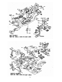
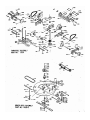
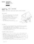
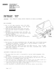
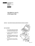
TECHNICAL
DATA
BROCHURE
ZTR
308-311
IMPORTANT - READ OPERATOR'S MANUAL BEFORE OPERATION.
Seat Adjustment
Loosen Bolts on sliding brackets under each side of seat, slide seat forward or rearward to
desired position. Re -tighten bolts. Do not operate mower w i t h bracket bolts in a l o o s e
condition.
Mower Blade Operation
To start mower b l a d e s , move l e v e r on f l o o r s l o w l y to "ENGAGE" p o s i t i o n . To stop
mower b l a d e s , move l e v e r on floor s l o w l y to "DISENGAGE" p o s i t i o n .
Body Removal
1. Disconnect throttle cable from engine.
2. Disconnect the rear wiring loom (P/N 4109) from the body by lightly squeezing the EconoSeal plug. This is located at the left rear of the body.
3. Note: Loosen bolts that hold body switch ( P / N 4079) and s l i d e switch away from engaging
rod. Tighten one bolt just enough to hold s w i t c h in this position until body is
reassembled.
4. Remove 4 control l e v e r bolts and remove upper control l e v e r s ( P / N 1501L-1501R).
5. Remove engaging handle ( P / N 6089) by removing b o l t and nut under handle.
6. Remove the 2 attach nuts on f l o o r of body and 2 sheet metal screws at the rear of body.
7. Place height adjustment lever in vertical position, engage parking brake and c a r e f u l l y l i f t
body up and off c h a s s i s .
8. Reverse the above procedure for a s s e m b l y .
Safety Checks
With the mower deck in the engaged p o s i t i o n slide the body s w i t c h (P/N 4 0 7 9 ) toward
the engaging rod (P/N 6087-1) until the switch leaf j u s t makes contact with the
s w i t c h button. Tighten both bolts in switch bracket.
W i t h mower deck engaged, attempt to start engine in all cutting height positions.
If engine starts in any cutting height position, re -adjust the s w i t c h . Disengage
the mower deck and start the engine in each cutting height position. If engine
fails to start in any cutting height position, re-adjust switch.
With operator in normal mowing/ p o s i t i o n , engage mower deck and remove w e i g h t from
seat. The engine should stop. Repeat this procedure in each cutting height
position. If engine does not stop when operator rises from seat in each cutting
height position, return to an authorized Dixon dealer for adjustment f>r repairs.
Parking Brake Adjustment
Remove body as described above. Tighten nut on brake rod (P/N2533) (Located in front of the
transaxle on each s i d e . ) , j u s t enough to prevent brake from s l i p p i n g when engaged. CAUTION:
Over tightening may c a u s e premature wear on brake band (P/N 5 0 8 5 ) .
Mower Drive Belt Adjustment
Belt tension for mower drive belt (P/N 2412) is adjusted by loosening nut on the c o n n e c t i n g
arm a s s e m b l y ( P / N 2 1 7 1 -A ) and turning bolt to a c h i e v e d e s i r e d t e n s i o n . Re -tighten nut.
Tension should be checked with belt in engaged position.
Removing Mower Deck
1. Remove engaging handle (P/N 6089) by removing bolt and nut under handle.
2. Loosen belt keeper (P/N 2234) located under engine by loosening 2 rear engine
mount bolts to a l l o w mower deck drive belt to come free of rear pulley.
R e -tighten belt keeper,
(continued on back)
1
DIXON INDUSTRIES, INC. B OX 484, COFFEYVILLE, KANSAS 67337 (316) 251-2000
D.I. Form S -35 ( R e v . 6/83)
3
4
ART # NAME
1015 Caster Weldment
1020 Caster Axle
1022 Caster Wheel & T1re
1022A Caster Wheel Bearing
I030 Upper Lift Link-Rear
I039 Lower Lift Link
1108 Tire - Front Wheel
1109 Inner Tube - Front Wheel
1501R Upper Control Lever
ISOIL Upper Control Lever
1507 Wheel/Deck Hub Bearing
1536 Chain Connecting Link
1540 Engine Shaft Key
543
Lift Knob
544
Bellcrank
560-1 Battery Splash Guard
574 Brake Pivot Weldment
606 Brake Mount Weldment
647
Control Pin
654 Transaxle Idler Weld.
655 Transaxle Idler Pulley
657 Transaxle Idler Spring
2000-2 Frame Weldment
2077 Walking Beam Weldment
2100 Bumper Weldment
2105 Bumper Pad
2154 Hub Pulley Spacer
2155 Hub Bearing Spacer
2159 Engaging Idler Spacer
2164 Support Sprocket Spacer
2165-1 Torque Rod
2166 Pivot Bolt
2171A Connecting Arm Assy.
2171-1 Connecting Arm Weldment
2172 Swivel Fitting
2176 Body
2179 Switch Bracket-Body
2180 Switch Bracket-Sw. Sect.
2204 Wheel Hub
2214R Brake Arm Weldment R
2214L Brake Arm Weldment L
2221 Transaxle Shim 16ga
2222 Transaxle Shim 22ga
2225 Battery Box Weldment
2231 Lower Control Lever Assy
2234 Belt Keeper
2237 Tie Bar Assy.
2238 Tie Bar
2240 Short Brake Rod Assy.
2402 Rear Wheel & Tire
406 30" Mower Blade
408 Drive Chain Assy.
411 Mower Deck V-Pulley
412 Deck Drive Belt
413 V-Idler Pulley
414 Engaging Idler Tension Sprg
417 Control Rod Assy
418 Long Brake Rod Assy
422 Name Decal
436 Switch Decal
PART # NAME
2444
Battery Ground Cable
2449
Caster Nipple
2452
Engaging Idler Bshg.
2456
Model Decal-ZTR 308
2460
Parking Brake Decal
2463
Seat
2465
Rear Tire(16x6.5-8)
2466
Rear Rim (16x6.5-8)
2468
Double Engine Pulley
2469
V-Belt
2470
Transaxle Pulley
2501
Rear Tube' Weldment
2504
Front Tube
2507
Support L
2508
Support R
2509
Support Shaft
2514 Torque Rod Stiffener R
2515
Torque Rod Stiffener L
2524
Transaxle
2600-3 Mower Deck Assy.
2601-2 Mower Deck Weldment
2612 Engaging Idler Weld.
2620-1 Engaging Rod
2626 Deflector Sheet
2640 Mower Deck Hub Assy.
2641 Mower Deck Hub Sub-Assy.
2642 Mower Deck Hub
2645 Blade Shaft Weldment
2647 Blade Washer
2648 Deck Hub Key
2668 Stiffener
2823 Oil Drain Assy.
3029 Front Grommet
3120 Nylon Shoulder Bshg.
3123 Control Pin
3129 Plastic Tube Closure
3502 Hand Grip
3504 Double Ball Joint
3507 Floor Pad -Long
3508 Floor Pad -Short
3511 Adhesive Bumper Pad
3521 Engaging Cam Mount Bshg.
3531 Decal-Operating Inst.
3532 Decal-Blade Drive
3533 Decal-Cutting Height
3536 Warning Label-Danger
4005B Throttle Cable
4006-2 Solenoid-Starter Cable
4006-8 Solenoid-Battery Cable
4007-1 Battery-12V
4009 Wire Clip(not shown)
4013 Wire Tie (not shown)
4047 Seat Switch
4067 Ignition Switch
4067A Switch Key (for 4067)
4075 10 AMP Fuse
4079 Body Switch
4092 Fuse Holder
4109 Rear Wiring Loom
4115 Wiring Kit
PART #
4122
4124
4148
5005
5007
5009R
5009L
5012
5013
5015
5016
5018
5019
5021
5024-1
5028
5036
5046
5047
5053
6059
6089
6107
6136-2
6159
NAME
Body Wiring Loom
Solenoid
Seat Angle
Discup
Cone Frame
Cradle
Cradle
Cradle Shaft
Cone Frame Shaft
24T Sprocket
Molded Cone
9T Sprocket-Narrow
Transaxle Chain
9T Sprocket-Wide
Cradle Spring
Transaxle Bearing
Pivot Spring
Positive Neutral R
Positive Neutral S
Brake Arm Retainer
Flat Idler Pulley
Engaging Handle
Deck Pin
Engaging Cam Weld.
Stabilizer Arm Wel