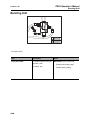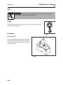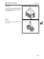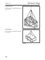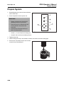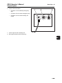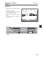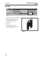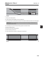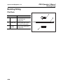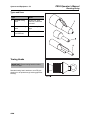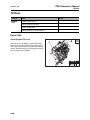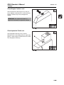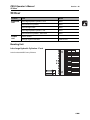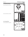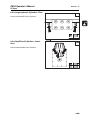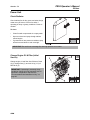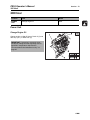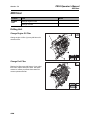
1
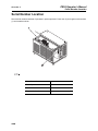
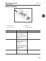
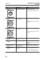
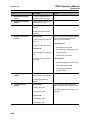
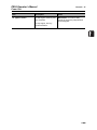
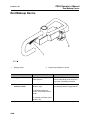
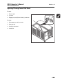
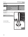
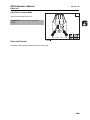
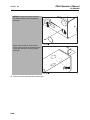
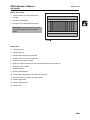
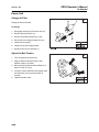
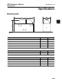
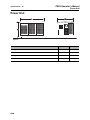
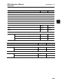
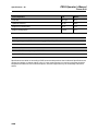
PR95
Operator’s
Manual
CMW®
Issue 1.0
053- 1102
PR95 Operator’s Manual
Overview - 1
Overview
Chapter Contents
Serial Number Location . . . . . . . . . . . . . . . . . . . . . . 2
Intended Use . . . . . . . . . . . . . . . . . . . . . . . . . . . . . . . 3
Unit Components . . . . . . . . . . . . . . . . . . . . . . . . . . . 3
Operator Orientation. . . . . . . . . . . . . . . . . . . . . . . . . 4
About This Manual . . . . . . . . . . . . . . . . . . . . . . . . . . 4
•
Bulleted Lists. . . . . . . . . . . . . . . . . . . . . . . . . . . . . . . . . . . . . . . . . . . . . . .4
•
Numbered Lists . . . . . . . . . . . . . . . . . . . . . . . . . . . . . . . . . . . . . . . . . . . . .4
•
“Continued” Indicators . . . . . . . . . . . . . . . . . . . . . . . . . . . . . . . . . . . . . . .4
CMW
PR95 Operator’s Manual
Overview - 2
Serial Number Location
Serial Number Location
Record serial numbers and date of purchase in spaces provided. Power unit (2) and engine serial numbers
(1) are located as shown.
Date of manufacture
Date of purchase
Power unit serial number
Engine serial number
CMW
PR95 Operator’s Manual
Overview - 3
Intended Use
Intended Use
Ditch Witch pipe bursters are intended for the replacement of buried pipes and conduits. The PR95
produces 187,400 lb (88 t) of pullback force. A power unit provides hydraulic power to run the pipe burster.
The unit is designed for operation in temperatures typically experienced in earth moving and construction
work environments. Provisions may be required to operate in extreme temperatures. Contact your Ditch
Witch dealer. Use in any other way is considered contrary to the intended use.
Ditch Witch pipe bursters and power units should be operated, serviced, and repaired only by persons
familiar with their particular characteristics and acquainted with the relevant safety procedures.
Unit Components
1. Power unit
3. Bursting unit
2. Accessory kit
4. Rod makeup device
CMW
Overview - 4
PR95 Operator’s Manual
Operator Orientation
Operator Orientation
IMPORTANT: Top view of unit is shown.
1. Front of unit
2. Right side of unit
3. Rear of unit
4. Left side of unit
About This Manual
This manual contains information for the proper use of this machine. See Operation Overview for basic
operating procedures. Cross references such as “See page 50” will direct you to detailed procedures.
Bulleted Lists
Bulleted lists provide helpful or important information or contain procedures that do not have to be
performed in a specific order.
Numbered Lists
Numbered lists contain illustration callouts or list steps that must be performed in order.
“Continued” Indicators
indicates that a procedure is continued on the next page.
CMW
PR95 Operator’s Manual
Foreword - 5
Foreword
This manual is an important part of your equipment. It provides safety information and operation
instructions to help you use and maintain your Ditch Witch equipment.
Read this manual before using your equipment. Keep it with the equipment at all times for future reference.
If you sell your equipment, be sure to give this manual to the new owner.
If you need a replacement copy, contact your Ditch Witch dealer. If you need assistance in locating a
dealer, visit our website at www.ditchwitch.com or write to the following address:
The Charles Machine Works, Inc.
Attn: Marketing Department
PO Box 66
Perry, OK 73077-0066
USA
The descriptions and specifications in this manual are subject to change without notice. The Charles
Machine Works, Inc. reserves the right to improve equipment. Some product improvements may have
taken place after this manual was published. For the latest information on Ditch Witch equipment, see your
Ditch Witch dealer.
Thank you for buying and using Ditch Witch equipment.
CMW
PR95 Operator’s Manual
Foreword - 6
PR95
Operator’s Manual
Issue number 1.0/OM-9/06
Part number 053-1102
Copyright 2006
by The Charles Machine Works, Inc.
, Ditch Witch, CMW, AutoCrowd, Modularmatic, Jet Trac, Roto Witch, Subsite,
Fluid Miser, Perma-Soil, Power Pipe, Super Witch, Super Witch II, Pierce Airrow, The Underground, and
The Underground Authority Worldwide are registered trademarks of The Charles Machine Works, Inc.
CMW
PR95 Operator’s Manual
Contents - 7
Contents
Overview
1
machine serial number, information about the type of work this machine is designed
to perform, basic machine components, and how to use this manual
Foreword
5
part number, revision level, and publication date of this manual, and factory contact
information
Safety
9
machine safety alerts and emergency procedures
Controls
19
machine controls, gauges, and indicators and how to use them
Prepare
29
procedures for inspecting and classifying the jobsite, planning the installation, and
preparing the jobsite for work
Transport
39
procedures for lifting and hauling
Burst Pipe
43
procedures for setting up equipment and performing the burst
Systems and Equipment
51
bursting string, accessory kit
Complete the Job
57
procedures for restoring the jobsite and storing equipment
Service
59
service intervals and instructions for this machine including lubrication, replacement
of wear items, and basic maintenance
Specifications
85
machine specifications including weights, measurements, power ratings, and fluid
capacities
Support
89
the warranty policy for this machine, and procedures for obtaining warranty
consideration and training
CMW
Contents - 8
Service Record
a record of major service performed on the machine
CMW
PR95 Operator’s Manual
93
PR95 Operator’s Manual
Safety - 9
Safety
Chapter Contents
Guidelines . . . . . . . . . . . . . . . . . . . . . . . . . . . . . . . . 10
Safety Alert Classifications . . . . . . . . . . . . . . . . . . 11
Safety Alerts . . . . . . . . . . . . . . . . . . . . . . . . . . . . . . 12
Emergency Procedures . . . . . . . . . . . . . . . . . . . . . 15
•
Electric Strike Description . . . . . . . . . . . . . . . . . . . . . . . . . . . . . . . . . . . .15
•
If an Electric Line is Damaged . . . . . . . . . . . . . . . . . . . . . . . . . . . . . . . .16
•
If a Gas Line is Damaged . . . . . . . . . . . . . . . . . . . . . . . . . . . . . . . . . . . .17
•
If a Fiber Optic Cable is Damaged . . . . . . . . . . . . . . . . . . . . . . . . . . . . .17
•
If Machine Catches on Fire . . . . . . . . . . . . . . . . . . . . . . . . . . . . . . . . . . .17
CMW
Safety - 10
PR95 Operator’s Manual
Guidelines
Guidelines
Follow these guidelines before operating any jobsite equipment:
•
Complete proper training and read operator’s manual before using equipment.
•
Contact One-Call (888-258-0808) and any utility companies which do not subscribe to One-Call. Have
all underground pipes and cables located and marked before operating equipment. If you damage a
utility, contact utility company.
•
Classify jobsite based on its hazards and use correct tools and machinery, safety equipment, and work
methods for jobsite.
•
Mark jobsite clearly and keep spectators away.
•
Wear personal protective equipment.
•
Review jobsite hazards, safety and emergency procedures, and individual responsibilities with all
personnel before work begins. Safety videos are available from your Ditch Witch dealer.
•
Replace missing or damaged safety shields and safety signs.
•
Use equipment carefully. Stop operation and investigate anything that does not look or feel right.
•
Do not operate unit where flammable gas is present.
•
Contact your Ditch Witch dealer if you have any question about operation, maintenance, or equipment
use.
CMW
PR95 Operator’s Manual
Safety - 11
Safety Alert Classifications
Safety Alert Classifications
These classifications and the icons defined on the following pages work together to alert you to situations
which could be harmful to you, jobsite bystanders or your equipment. When you see these words and
icons in the book or on the machine, carefully read and follow all instructions. YOUR SAFETY IS AT
STAKE.
Watch for the three safety alert levels: DANGER, WARNING and CAUTION. Learn what each level
means.
indicates an imminently hazardous situation which, if not avoided, will result in death or
serious injury.
indicates a potentially hazardous situation which, if not avoided, could result in death or
serious injury.
indicates a potentially hazardous situation which, if not avoided, may result in minor or
moderate injury.
Watch for two other words: NOTICE and IMPORTANT.
NOTICE can keep you from doing something that might damage the machine or someone's property. It
can also alert you against unsafe practices.
IMPORTANT can help you do a better job or make your job easier in some way.
CMW
PR95 Operator’s Manual
Safety - 12
Safety Alerts
Safety Alerts
Electric shock. Contacting electric lines will cause death or serious injury.
Know location of lines and stay away.
Deadly gases. Lack of oxygen or presence of gas will cause sickness or
death. Provide ventilation.
Moving tools will kill or injure. Never use wrenches or tools on moving rods
and burster unit components when unit is operating.
Jobsite hazards could cause death or serious injury. Use
correct equipment and work methods. Use and maintain proper safety
equipment.
Crushing weight could cause death or serious injury. Use
proper procedures and equipment or stay away.
Moving parts on unit could cut off hand or foot. Stay away.
CMW
PR95 Operator’s Manual
Safety - 13
Safety Alerts
Incorrect procedures could result in death, injury, or property damage.
Learn to use equipment correctly.
Improper control function could cause death or serious injury. If control does
not work as described in instructions, stop machine and have it serviced.
Looking into fiber optic cable could result in permanent vision damage. Do
not look into ends of fiber optic or unidentified cable.
Pressurized fluid or air could pierce skin and cause injury or
death. Stay away.
Fire or explosion possible. Fumes could ignite and cause burns. No
smoking, no flame, no spark.
Moving traffic - hazardous situation. Death or serious injury could result.
Avoid moving vehicles, wear high visibility clothing, post appropriate warning signs.
Hot pressurized cooling system fluid could cause serious burns. Allow to
cool before servicing.
CMW
PR95 Operator’s Manual
Safety - 14
Safety Alerts
Flying objects may cause injury. Wear hard hat and safety glasses.
Hot parts may cause burns. Do not touch until cool.
Exposure to high noise levels may cause hearing loss. Wear hearing
protection.
Fall possible. Slips or trips may result in injury. Keep area clean.
Battery acid may cause burns. Avoid contact.
Improper handling or use of chemicals may result in illness, injury, or
equipment damage. Follow instructions on labels and in material safety data sheets
(MSDS).
CMW
PR95 Operator’s Manual
Safety - 15
Emergency Procedures
Emergency Procedures
Before operating any equipment, review emergency procedures and check that all safety precautions have
been taken.
EMERGENCY SHUTDOWN - Turn ignition switch to stop position or push remote engine stop button.
Electric Strike Description
When working near electric cables, remember the following:
•
Electricity follows all paths to ground, not just path of least resistance.
•
Pipes, hoses, and cables will conduct electricity back to all equipment.
•
Low voltage current can injure or kill. Almost one-third of work-related electrocutions result from
contact with less than 440 volts.
Most electric strikes are not noticeable, but indications of a strike include:
•
power outage
•
smoke
•
explosion
•
popping noises
•
arcing electricity
If any of these occur, assume an electric strike has occurred.
CMW
Safety - 16
PR95 Operator’s Manual
Emergency Procedures
If an Electric Line is Damaged
If you suspect an electric line has been damaged and you are in pit, DO NOT MOVE. Remain in pit and
take the following actions. The order and degree of action will depend upon the situation.
•
Warn people nearby that an electric strike has occurred. Instruct them to leave the area and contact
utility.
•
Contact utility company to shut off power.
•
Do not leave pit until given permission by utility company.
If you suspect an electric line has been damaged and you are out of pit, DO NOT TOUCH ANYTHING IN
PIT. Take the following actions. The order and degree of action will depend upon the situation.
•
LEAVE AREA. The ground surface may be electrified, so take small steps with feet close together to
reduce the hazard of being shocked from one foot to the other. For more information, contact your
Ditch Witch dealer.
•
Contact utility company to shut off power.
•
Do not return to jobsite or allow anyone into area until given permission by utility company.
If you suspect an electric line has been damaged and you are on other piece of equipment, DO NOT
MOVE. Remain on truck or trailer and take the following actions. The order and degree of action will
depend on the situation.
•
Warn people nearby that an electric strike has occurred. Instruct them to leave the area and contact
utility.
•
Contact utility company to shut off power.
•
Do not return to area or allow anyone into area until given permission by utility company.
If you suspect an electric line has been damaged and you are off other piece of equipment, DO NOT
TOUCH EQUIPMENT. Take the following actions. The order and degree of action will depend on the
situation.
•
LEAVE AREA.
•
Contact utility company to shut off power.
•
Do not return to area or allow anyone into area until given permission by utility company.
CMW
PR95 Operator’s Manual
Safety - 17
Emergency Procedures
If a Gas Line is Damaged
If you suspect a gas line has been damaged, take the following actions. The order and degree of action will
depend on the situation.
•
Immediately shut off engine(s), if this can be done safely and quickly.
•
Remove any ignition source(s), if this can be done safely and quickly.
•
Warn others that a gas line has been cut and that they should leave the area.
•
Leave jobsite as quickly as possible.
•
Immediately call your local emergency phone number and utility company.
•
If jobsite is along street, stop traffic from driving near jobsite.
•
Do not return to jobsite until given permission by emergency personnel and utility company.
If a Fiber Optic Cable is Damaged
Do not look into cut ends of fiber optic or unidentified cable. Vision damage can occur.
If Machine Catches on Fire
Perform emergency shutdown procedure and then take the following actions. The order and degree of
action will depend on the situation.
•
Immediately move battery disconnect switch (if equipped) to disconnect position.
•
If fire is small and fire extinguisher is available, attempt to extinguish fire.
•
If fire cannot be extinguished, leave area as quickly as possible and contact emergency personnel.
CMW
Safety - 18
PR95 Operator’s Manual
Emergency Procedures
CMW
PR95 Operator’s Manual
Controls - 19
Controls
Chapter Contents
Bursting Unit . . . . . . . . . . . . . . . . . . . . . . . . . . . . . 20
Remote Controller . . . . . . . . . . . . . . . . . . . . . . . . . 21
Power Unit . . . . . . . . . . . . . . . . . . . . . . . . . . . . . . . 23
Rod Makeup Device . . . . . . . . . . . . . . . . . . . . . . . . 28
CMW
PR95 Operator’s Manual
Controls - 20
Bursting Unit
Bursting Unit
Front jaw control
Item
Description
Notes
Front jaw control
To enable automatic front jaw
operation, push.
IMPORTANT: Use in pull mode.
To disable, pull.
CMW
•
Enable when bursting pipe.
•
Disable when pushing.
PR95 Operator’s Manual
Controls - 21
Remote Controller
Remote Controller
1. Work button (white)
3. Mode switch
2. Return button (black)
4. Emergency stop switch
Item
Description
1. Work button (white)
With mode selector in push
mode, push and hold to push
rod into existing pipe.
Notes
With mode selector in pull
mode, push and hold to pull
new pipe.
2. Return button (black)
With mode selector in push
mode, push and hold to return
carriage to back of unit. Jaws
close when button is
released.
With mode selector in pull
mode, push and hold to return
carriage to front of unit. Jaws
close when button is
released.
3. Mode selector
To enter pull mode, move left.
Decal is marked “reverse.”
To enter push mode, move
right.
CMW
PR95 Operator’s Manual
Controls - 22
Remote Controller
Item
Description
Notes
4. Emergency stop switch
Push to stop power unit
engine.
IMPORTANT: All emergency stops
must be connected and disengaged
for unit to start.
CMW
PR95 Operator’s Manual
Controls - 23
Power Unit
Power Unit
Gauges and Indicators
1. Hourmeter
5. Engine preheater indicator
2. Main cylinders pressure gauge
6. Engine oil pressure indicator
3. Jaw system pressure gauge
7. Coolant temperature indicator
4. Battery charge indicator
CMW
PR95 Operator’s Manual
Controls - 24
Power Unit
Item
Description
Notes
1. Hourmeter
Displays engine operating
time.
Gauge is marked “hours.”
Use these times to schedule service.
2. Main cylinders pressure
gauge
Displays hydraulic pressure
at main cylinders.
Gauge is marked “pump pressure
main.”
Full load reading should be 3600 psi
(248 bar).
3. Jaw system pressure
gauge
Displays hydraulic pressure in
jaw system.
Gauge is marked “pump pressure
jaws.”
Full load reading should be 3600 psi
(248 bar).
4. Battery charge
indicator
Lights when battery is not
charging.
Indicator is marked “charge.”
5. Engine preheater
indicator
Lights when glow plugs are
on.
Indicator is marked “glow.”
IMPORTANT: Start engine after light
goes off.
6. Engine oil pressure
indicator
Lights when engine oil
pressure is low.
Indicator is marked “oil pressure.”
7. Coolant temperature
indicator
Lights if cooling system fluid
overheats.
Indicator is marked “water temp.”
CMW
•
Turn off engine and let cool.
•
Check cooling system fluid level.
PR95 Operator’s Manual
Controls - 25
Power Unit
Controls
1. Bursting unit engage control
6. Throttle
2. Bursting unit standby control
7. Bursting unit manual control
3. Emergency stop switch
8. Rod makeup manual control
4. Rod makeup engage control
9. Rear jaw manual control
5. Rod makeup standby control
10. Ignition switch
Item
Description
1. Bursting unit engage
control
To turn on hydraulic flow to
bursting unit, press.
2. Bursting unit standby
control
To stop hydraulic flow to
bursting unit, press.
3. Emergency stop switch
To turn off power unit engine,
press.
Notes
IMPORTANT: All emergency stops
must be connected and disengaged
for unit to start.
CMW
PR95 Operator’s Manual
Controls - 26
Power Unit
Item
Description
4. Rod makeup engage
control
To turn on hydraulic flow to
rod makeup device, press.
5. Rod makeup standby
control
To stop hydraulic flow to rod
makeup device, press.
6. Throttle
To increase engine speed,
push up.
Notes
To decrease engine speed,
pull down.
7. Bursting unit manual
control
In push mode:
To return carriage to back of
unit, pull.
Use in sequence with rear jaw manual
control to push and pull rods from
power unit control station.
Push sequence:
To push rod into pipe, push.
In pull mode:
To pull new pipe through pipe,
pull.
To return carriage to front of
unit, push.
8. Rod makeup manual
control
•
push jaw manual control
•
push bursting unit manual control
•
pull jaw control
•
pull bursting unit control
Pull sequence:
•
push bursting unit manual control
•
push jaw manual control
•
pull bursting unit control
•
pull jaw control
To engage hydraulics to rod
makeup device, pull and hold.
To disengage hydraulics,
release.
9. Rear jaw manual
control
In push mode:
Use in sequence with bursting unit
manual control to push and pull rods.
To close jaws, pull.
To open jaws, push.
In pull mode:
To close jaws, push.
To open jaws, pull.
CMW
See “Bursting unit manual control” for
sequence.
PR95 Operator’s Manual
Controls - 27
Power Unit
Item
Description
Notes
10. Ignition switch
To start engine, insert key and
turn clockwise.
IMPORTANT: If unit won’t start,
ensure all emergency stop switches
are disengaged.
To stop engine, turn key
counterclockwise.
CMW
PR95 Operator’s Manual
Controls - 28
Rod Makeup Device
Rod Makeup Device
1. Engage switch
2. Rotation speed/direction control
Item
Description
Notes
1. Engage switch
Press switch to engage rod
makeup device.
IMPORTANT: Jaws must be closed
before unthreading rod in rod device
to prevent unthreading downhole.
2. Rotation speed/
direction control
To thread rods faster, move
handle to right.
IMPORTANT: Direction is determined
from standing behind engage handle.
To thread/unthread rods
slower, move handle toward
center.
To unthread rods faster, move
handle to left.
CMW
PR95 Operator’s Manual
Prepare - 29
Prepare
Chapter Contents
Gather Information . . . . . . . . . . . . . . . . . . . . . . . . . 30
•
Review Job Plan . . . . . . . . . . . . . . . . . . . . . . . . . . . . . . . . . . . . . . . . . . .30
•
Notify One-Call Services . . . . . . . . . . . . . . . . . . . . . . . . . . . . . . . . . . . . .30
•
Examine Pullback Material . . . . . . . . . . . . . . . . . . . . . . . . . . . . . . . . . . .30
•
Arrange for Traffic Control. . . . . . . . . . . . . . . . . . . . . . . . . . . . . . . . . . . .30
•
Plan for Emergency Services . . . . . . . . . . . . . . . . . . . . . . . . . . . . . . . . .30
Inspect Site . . . . . . . . . . . . . . . . . . . . . . . . . . . . . . . 31
•
Identify Hazards . . . . . . . . . . . . . . . . . . . . . . . . . . . . . . . . . . . . . . . . . . .32
•
Select Exit and Burster Pit Locations . . . . . . . . . . . . . . . . . . . . . . . . . . .33
Plan Bore Path . . . . . . . . . . . . . . . . . . . . . . . . . . . . 34
Prepare Jobsite . . . . . . . . . . . . . . . . . . . . . . . . . . . . 34
•
Mark Burst Path . . . . . . . . . . . . . . . . . . . . . . . . . . . . . . . . . . . . . . . . . . .34
•
Prepare Entry Point. . . . . . . . . . . . . . . . . . . . . . . . . . . . . . . . . . . . . . . . .35
Check Supplies and Prepare Equipment . . . . . . . 36
•
Check Supplies . . . . . . . . . . . . . . . . . . . . . . . . . . . . . . . . . . . . . . . . . . . .36
•
Prepare Equipment . . . . . . . . . . . . . . . . . . . . . . . . . . . . . . . . . . . . . . . . .37
•
Assemble Accessories . . . . . . . . . . . . . . . . . . . . . . . . . . . . . . . . . . . . . .37
CMW
Prepare - 30
PR95 Operator’s Manual
Gather Information
Gather Information
A successful job begins before the burst. The first step in planning is reviewing information already
available about the job and jobsite.
Review Job Plan
Review blueprints or other plans and make sure you have taken enlargement during pullback into account.
Check for information about existing or planned structures, elevations, or proposed work that may be
taking place at the same time.
Notify One-Call Services
Call area One-Call or similar services and have existing lines located and marked. Call any utilities in your
area that do not subscribe to One-Call.
Examine Pullback Material
Ask for a sample of the material you will be pulling back. Check its weight and stiffness. Contact the
manufacturer for bend radius information. Check that you have appropriate pullback devices.
Arrange for Traffic Control
If working near a road or other traffic area, contact local authorities about safety procedures and
regulations.
Plan for Emergency Services
Have the telephone numbers for local emergency and medical facilities on hand. Check that you will have
access to a telephone.
CMW
PR95 Operator’s Manual
Prepare - 31
Inspect Site
Inspect Site
Inspect jobsite before transporting equipment. Check for the following:
Inspect jobsite before transporting equipment. Check for the following:
•
changes in elevation such as hills or open trenches
•
obstacles such as buildings, railroad crossings, or streams
•
signs of utilities
– “buried utility” notices
– utility facilities without overhead lines
– gas or water meters
– junction boxes
– drop boxes
– light poles
– manhole covers
– sunken ground
•
traffic
•
access
•
soil type and condition
•
depths of existing pipes
CMW
PR95 Operator’s Manual
Prepare - 32
Inspect Site
Identify Hazards
•
Identify safety hazards. Follow U.S. Department of Labor regulations on excavating and trenching
(Part 1926, Subpart P) and other similar regulations.
•
Have an experienced locating equipment operator sweep area within 20’ (6 m) to each side of burst
path. Verify previously marked line and cable locations.
•
Mark location of all buried utilities and obstructions.
Jobsite hazards could cause death or serious injury. Use
correct equipment and work methods. Use and maintain proper safety
equipment.
NOTICE:
•
Wear personal protective equipment including hard hat, safety eye wear, and hearing protection.
•
Do not wear jewelry or loose clothing.
•
Notify One-Call and companies which do not subscribe to One-Call.
•
Comply with all utility notification regulations before digging or bursting.
•
Verify location of previously marked underground hazards.
•
Mark jobsite clearly and keep spectators away.
CMW
PR95 Operator’s Manual
Prepare - 33
Inspect Site
Select Exit and Burster Pit Locations
Consider the following when selecting pit locations:
Traffic
Vehicle and pedestrian traffic must be a safe distance from bursting equipment. Allow at least 10’ (3 m)
buffer zone around equipment.
Space
Check that starting and ending points allow enough space for exit and burster pits.
Check that exit area has enough space for product to be installed.
Check that there is enough space to work.
Access
Consider shade, wind, fumes, and other site features.
CMW
PR95 Operator’s Manual
Prepare - 34
Plan Burst Path
Plan Burst Path
Plan the burst path, from entry to end, before job begins. Locate the entire route of the pipe to be replaced
to ensure a straight path. Expose all crossing or parallel utilities within 18” (500 mm) of the pipe being
burst. Visually verify that bursting head does not damage utility.
Prepare Jobsite
Jobsite hazards could cause death or serious injury. Use
correct equipment and work methods. Use and maintain proper safety
equipment.
NOTICE:
•
Cutting high voltage cable can cause electrocution. Expose lines by hand before digging.
•
All vegetation near operator’s station must be removed. Contact with trees, shrubs, or weeds during
electrical strike could result in electrocution.
Mark Burst Path
Mark your planned burst path with flags or paint.
CMW
PR95 Operator’s Manual
Prepare - 35
Prepare Jobsite
Dig Launch and Burster Pits
Dimensions
Unit
PR95
Burster Pit
Exit Pit *
Length (A)
Width (B)
Length (C)
Width (D)
U.S. (metric)
U.S. (metric)
U.S. (metric)
U.S. (metric)
12’ (3.6 m)
5’ (1.5 m)
10’ (3 m)
3’ (1 m)
* Exit pit dimensions depend on pipe depth and product being installed.
Requirements
Exit Pit (1)
•
Must be in line with existing pipe.
•
Sloped back end aids new pipe entry.
Burster Pit (2)
•
Must be in line with existing pipe.
•
Must allow burster to be level with existing pipe.
CMW
Prepare - 36
PR95 Operator’s Manual
Check Supplies and Prepare Equipment
Check Supplies and Prepare Equipment
Check Supplies
•
marking flags or paint
•
fuel
•
keys
•
cutting heads, clevis
•
barrier cones and tape
•
spray lubricant (such as WD-40)
•
personal protective equipment, such as hard hat and safety glasses
•
notepad and pencil
CMW
PR95 Operator’s Manual
Prepare - 37
Check Supplies and Prepare Equipment
Prepare Equipment
Fluid Levels
•
fuel
•
hydraulic fluid
•
engine coolant
•
battery charge
•
engine oil
Condition and Function
•
filters (air, oil, hydraulic)
•
couplers
•
pumps and motors
•
hoses and valves
Assemble Accessories
Fire Extinguisher
If required, mount a fire extinguisher near the power unit but away from possible points of ignition. The fire
extinguisher should always be classified for both oil and electric fires. It should meet legal and regulatory
requirements.
CMW
Prepare - 38
PR95 Operator’s Manual
Check Supplies and Prepare Equipment
CMW
PR95 Operator’s Manual
Transport - 39
Transport
Chapter Contents
Lift . . . . . . . . . . . . . . . . . . . . . . . . . . . . . . . . . . . . . . 40
•
Points . . . . . . . . . . . . . . . . . . . . . . . . . . . . . . . . . . . . . . . . . . . . . . . . . . .40
•
Procedure . . . . . . . . . . . . . . . . . . . . . . . . . . . . . . . . . . . . . . . . . . . . . . . .40
CMW
PR95 Operator’s Manual
Transport - 40
Lift
Lift
Crushing weight. If load falls or moves it could kill or crush you. Use
proper procedures and equipment or stay away.
Points
Lifting points are identified by lifting decals. Lifting at other points is unsafe
and can damage machinery.
Procedure
Bursting Unit
Use a crane capable of supporting the equipment's
size and weight. See “Specifications” on page 85
or measure and weigh equipment before lifting.Use
lift points as shown.
CMW
PR95 Operator’s Manual
Transport - 41
Lift
Power Pack
Use a crane capable of supporting the equipment's
size and weight. See “Specifications” on page 85
or measure and weigh equipment before lifting.
Use lift points as shown.
Rod Box
Use a crane capable of supporting the equipment's
size and weight.
CMW
Transport - 42
PR95 Operator’s Manual
Lift
Extension Frame
Use a crane capable of supporting the equipment's
size and weight.
Accessory Kit
Use a crane capable of supporting the equipment's
size and weight.
CMW
PR95 Operator’s Manual
Burst Pipe - 43
Burst Pipe
Chapter Contents
Prepare System . . . . . . . . . . . . . . . . . . . . . . . . . . . 44
Push Rods . . . . . . . . . . . . . . . . . . . . . . . . . . . . . . . 46
Connect . . . . . . . . . . . . . . . . . . . . . . . . . . . . . . . . . . 47
Pull Pipe . . . . . . . . . . . . . . . . . . . . . . . . . . . . . . . . . 48
CMW
Burst Pipe - 44
PR95 Operator’s Manual
Prepare System
Prepare System
1. Unload bursting unit, power unit and rod boxes
next to burster pit.
2. Connect hydraulic hoses to power unit.
IMPORTANT:
•
Ensure connectors are clean before
threading hoses onto connectors.
•
Each connector is a different size and
will only attach to the same-sized
connector.
•
Connect hose 5 first and work up to
hose 1 for easy access.
•
Hoses 1, 2, 3 and 5 are from bursting unit.
•
Hoses 4 and 6 are from rod makeup device.
3. Tighten hoses fully.
4. Lower bursting unit into pit. Use boards to ensure rods will be level with existing pipe.
5. Place end of rod makeup device arm into hole
on end of rear of bursting unit.
CMW
PR95 Operator’s Manual
Burst Pipe - 45
Prepare System
6. Connect electrical cables.
•
Connector 1 is for stationary emergency
stop
•
Connector 2 is for remote emergency stop
•
Connector 3 is for remote bursting unit
control
7. Connect ground rod to bursting unit.
8. Drive ground rod into soil at front of pit.
CMW
Burst Pipe - 46
PR95 Operator’s Manual
Push Rods
Push Rods
IMPORTANT: If bursting unit or rod makeup device does not work,
•
Ensure all emergency stops are connected and disengaged.
•
Check all hydraulic and electrical connections.
1. Start power unit engine.
2. Assemble pilot rod. See “Pilot Rods” on page 52.
3. Disable brake.
4. Thread 2-3 rods together.
IMPORTANT: Spray lubricant (such as WD-40) on threads of each rod every use.
5. Put bursting unit into push mode and push rod string into existing pipe.
6. Thread next rod onto rod string loosely.
7. Swing rod makeup device into position and place collar onto end of rod.
8. Thread onto pipe loosely.
9. Turn rotation speed/direction control to right.
10. Press engage switch until rods thread together completely.
11. Move rod makeup device clear of rod.
12. Push rod into pipe.
13. Continue threading rods together and pushing into pipe until pilot assembly enters exit pit.
CMW
PR95 Operator’s Manual
Burst Pipe - 47
Connect
Connect
1. Install towing head (2) onto end of new pipe
(1).
2. Remove pilot rod assembly.
3. Install bursting head (5) over rod (6) and slide
forward until threads are visible.
4. Thread stop rod assembly (4) on end of rod
string.
5. Connect stop rod assembly to towing head
with a shackle (3).
CMW
Burst Pipe - 48
PR95 Operator’s Manual
Pull Pipe
Pull Pipe
1. Push bursting unit away from pit wall slightly.
2. Slide pulling brace (shown) into position.
Ensure brace is flush with pit wall.
3. Put bursting unit into pull mode.
4. Enable brake.
5. Pull back rod.
6. Unthread and place in rod box.
7. Continue pulling back rods until towing
assembly reaches burster pit.
CMW
PR95 Operator’s Manual
Burst Pipe - 49
Pull Pipe
8. Thread one rod onto rod in bursting unit.
9. Remove rod makeup device.
10. Push bursting unit back slightly to remove pulling brace.
11. Move burster back in pit and position extension frame between between pipe burster and existing pipe.
IMPORTANT: Ensure extension frame is level and centered. Pull bursting unit forward until it is
firmly against extension frame.
12. Put bursting unit in pull mode and pull towing system into extension frame.
13. Remove extension frame.
14. Disconnect and remove towing system.
15. Remove bursting unit from pit.
16. Connect both ends of new pipe to existing pipe to complete job.
CMW
Burst Pipe - 50
PR95 Operator’s Manual
Pull Pipe
CMW
PR95 Operator’s Manual
Systems and Equipment - 51
Systems and Equipment
Chapter Contents
Bursting String . . . . . . . . . . . . . . . . . . . . . . . . . . . . 52
•
Pilot Rods . . . . . . . . . . . . . . . . . . . . . . . . . . . . . . . . . . . . . . . . . . . . . . . .52
•
Bursting Heads . . . . . . . . . . . . . . . . . . . . . . . . . . . . . . . . . . . . . . . . . . . .53
•
Towing Heads . . . . . . . . . . . . . . . . . . . . . . . . . . . . . . . . . . . . . . . . . . . . .54
Extension Frame . . . . . . . . . . . . . . . . . . . . . . . . . . 55
Accessory Kit . . . . . . . . . . . . . . . . . . . . . . . . . . . . . 55
CMW
Systems and Equipment - 52
PR95 Operator’s Manual
Bursting String
Bursting String
Pilot Rods
Type
Uses
1.
fiber pilot rod
used in pipes with
considerable joint
misalignment
2.
flexible pilot
rod
used in pipes with curves;
also used in failing pipes
3.
standard
pilot rod
used in pipes without joint
misalignment
CMW
PR95 Operator’s Manual
Systems and Equipment - 53
Bursting String
Bursting Heads
Identification
IMPORTANT: Ensure identification numbers on
stop rod system and bursting head match.
Stop rods and bursting heads are each marked
with an identification number. The length of the
stop rod and chain is optimized for each bursting
head. Always use matched components to prevent
shackle and new pipe damage during installation.
Components
IMPORTANT: Standard cutting head is shown.
Component
Description
1.
rear of bursting
head
fits OD of new pipe
being installed
2.
knife
cuts existing pipe
3.
front of bursting
head
fits inside existing pipe
4.
stop rod
connects rods in
existing pipe to towing
head
5.
d-link and chain
on stop rod
attaches new pipe to
stop rod system
CMW
Systems and Equipment - 54
PR95 Operator’s Manual
Bursting String
Types and Uses
Type
Uses
1.
standard cutting
head
ductile iron, steel,
cast iron, reinforced
concrete
2.
standard cracking
head
concrete, clay, fragile
pipe
3.
standard plastic
PVC/PE head
plastic PVC, PE
Towing Heads
IMPORTANT: Ensure towing head is sized to
match new pipe.
Standard towing head: attaches to new PE pipe
allowing it to be pulled through existing pipe after
bursting.
CMW
PR95 Operator’s Manual
Systems and Equipment - 55
Extension Frame
Extension Frame
The extension frame allows room to remove the
towing assembly from the new pipe after it enters
the bursting unit pit.
Accessory Kit
•
7’ chain set (for power unit, bursting unit)
•
3’ chain set (for smaller items)
•
grease gun and grease cartridges
•
ground rod
•
hand tools
•
slide hammers
•
remote control module
•
remote emergency stop modules
•
rod makeup device
CMW
Systems and Equipment - 56
PR95 Operator’s Manual
Accessory Kit
CMW
PR95 Operator’s Manual
Complete the Job - 57
Complete the Job
Chapter Contents
Stow Components . . . . . . . . . . . . . . . . . . . . . . . . . 58
Restore Jobsite . . . . . . . . . . . . . . . . . . . . . . . . . . . 58
CMW
Complete the Job - 58
PR95 Operator’s Manual
Stow Components
Stow Components
1. Install all covers.
2. Load components onto trailer.
3. Secure all components on trailer.
Restore Jobsite
Fill in entry and bursting pits.
CMW
PR95 Operator’s Manual
Service - 59
Service
Chapter Contents
Service Precautions . . . . . . . . . . . . . . . . . . . . . . . . 60
Recommended Lubricants/Service Key . . . . . . . . 62
Each Use . . . . . . . . . . . . . . . . . . . . . . . . . . . . . . . . . 64
10 Hour . . . . . . . . . . . . . . . . . . . . . . . . . . . . . . . . . . 66
50 Hour . . . . . . . . . . . . . . . . . . . . . . . . . . . . . . . . . . 69
200 Hour . . . . . . . . . . . . . . . . . . . . . . . . . . . . . . . . . 73
250 Hour . . . . . . . . . . . . . . . . . . . . . . . . . . . . . . . . . 75
400 Hour . . . . . . . . . . . . . . . . . . . . . . . . . . . . . . . . . 74
1000 Hour . . . . . . . . . . . . . . . . . . . . . . . . . . . . . . . . 76
As Needed . . . . . . . . . . . . . . . . . . . . . . . . . . . . . . . 77
CMW
PR95 Operator’s Manual
Service - 60
Service Precautions
Service Precautions
Incorrect procedures could result in death, injury, or property damage.
Learn to use equipment correctly.
NOTICES:
•
Unless otherwise instructed, all service should be performed with engine off.
•
Refer to engine manufacturer’s manual for engine maintenance instructions.
Welding Precaution
NOTICE: Welding can damage electronics.
•
Disconnect battery to prevent damage to battery. Do not turn off battery disconnect switch with
engine running, or alternator and other electronic devices may be damaged.
•
Connect welder ground clamp close to welding point and make sure no electronic components are
in the ground path.
•
Always disconnect the Engine Control Unit ground connection from the frame, harness connections
to the ECU, and other electronic components prior to welding on machine or attachments.
Washing Precaution
NOTICE: Water can damage electronics. When cleaning equipment, do not spray electrical components
with water.
CMW
PR95 Operator’s Manual
Service - 61
Service Precautions
Opening/Closing Power Unit Hood
To open
1. Remove pins.
2. Lift hood.
3. Engage prop rod (2) into holder (1) as shown.
To close
1. Disengage prop rod from holder.
2. Stow prop rod.
3. Carefully close hood.
4. Install pins.
CMW
PR95 Operator’s Manual
Service - 62
Recommended Lubricants/Service Key
Recommended Lubricants/Service Key
Item
Description
DEO
Diesel engine oil meeting or exceeding CD per the API service classification or E3 per
the European Automobile Manufacturer’s Association (ACEA) and SAE viscosity
recommended by engine manufacturer
MPG
Multipurpose grease meeting ASTM D217 and NLGI 5
THF
Tractor hydraulic fluid, similar to Phillips 66 HG, Mobilfluid 423, Chevron Tractor
Hydraulic Fluid, Texaco TDH Oil, Shell Tellus, or equivalent
AC
Automotive-type antifreeze/coolant meeting ASTM D3306
Check level of fluid or lubricant
Check condition
Filter
Change, replace, adjust, service or test
CMW
PR95 Operator’s Manual
Service - 63
Recommended Lubricants/Service Key
Proper lubrication and maintenance protects Ditch Witch equipment from damage and failure. Service
intervals listed are for minimum requirements. In extreme conditions, service machine more frequently.
Use only recommended lubricants. Fill to capacities listed in “Fluid Capacities” on page 88.
For more information on engine lubrication and maintenance, see your Kubota® engine manual.
NOTICE:
•
Use only genuine Ditch Witch parts, filters, approved lubricants, TJC, and approved coolants to
maintain warranty.
•
Use the “Service Record” on page 93 to record all required service to your machine.
Engine Oil Temperature Chart
Temperature range anticipated before next oil change
Approved Coolant
Add only only automotive-type antifreeze/coolant meeting ASTM D3306.
NOTICE: Do not use diesel engine antifreeze/coolant. This will lead to engine damage or premature
engine failure.
CMW
PR95 Operator’s Manual
Service - 64
Each Use
Each Use
Location
Task
Notes
BURSTING
UNIT
Lube front hydraulic pressure system components
MPG
Lube rear pin bolts
MPG
Lube rear pressure axles
MPG
Clean jaw threads
after each job
Bursting Unit
Lube Front Hydraulic Pressure System
Components
Lube 4 zerks with MPG each use.
IMPORTANT: Ensure front jaw is up before
lubing.
Lube Rear Pin Bolts
Lube 2 zerks with MPG each use.
CMW
PR95 Operator’s Manual
Service - 65
Each Use
Lube Rear Pressure Axles
Lube 2 zerks with MPG each use.
IMPORTANT: Ensure rear jaw is up before
lubing.
Clean Jaw Threads
Clean jaw threads with high-pressure water after each job.
CMW
PR95 Operator’s Manual
Service - 66
10 Hour
10 Hour
Location
Task
POWER
UNIT
Check engine oil level
Check hydraulic fluid level
Check coolant level
Check hydraulic hoses and fittings
Power Unit
Check Engine Oil Level
Check engine oil at dipstick (1) before operation
and every 10 hours thereafter. Check with unit on
level surface and at least 15 minutes after stopping
engine. Add DEO at fill (2) as necessary to keep oil
level at highest line on dipstick.
CMW
Notes
PR95 Operator’s Manual
Service - 67
10 Hour
Check Engine Coolant Level
Check coolant level, with engine cool, every 10
hours. Maintain coolant level at 1” (25 mm) below
bottom of radiator cap. If low, add approved
coolant.
IMPORTANT: See “Approved Coolant” on
page 63 for information on approved coolants.
Check Hydraulic Fluid Level
Check hydraulic fluid level every 10 hours.
Maintain fluid level at halfway point on upper sight
glass (1), when engine is off and fluid is cool. Add
THF at hydraulic fluid fill (2).
CMW
PR95 Operator’s Manual
Service - 68
10 Hour
Check Hydraulic Hoses
Check hydraulic hoses for leaks every 10 hours.
Pressurized fluid or air could pierce skin and cause injury
or death. Stay away.
NOTICE: Escaping pressurized fluid can cause injury or pierce skin and
poison.
•
Before disconnecting a hydraulic line, turn engine off and operate all controls to relieve pressure.
Lower, block, or support any raised component with a hoist. Cover connection with heavy cloth and
loosen connector nut slightly to relieve residual pressure. Catch all fluid in a container.
•
Before using system, check that all connections are tight and all lines are undamaged.
•
Fluid leaks can be hard to detect. Use a piece of cardboard or wood, rather than hands, to search
for leaks.
•
Wear protective clothing, including gloves and eye protection.
•
If you are injured, seek immediate medical attention from a doctor familiar with this type of injury.
CMW
PR95 Operator’s Manual
Service - 69
50 Hour
50 Hour
Location
Task
Notes
BURSTING
UNIT
Lube large hydraulic cylinders - front
MPG
Lube small front cylinders
MPG
Lube carriage rollers
MPG
Lube large hydraulic cylinders - rear
MPG
Lube small front cylinders - lower area
MPG
POWER
UNIT
Check radiator
Change engine oil and filter
Initial service
Bursting Unit
Lube Large Hydraulic Cylinders - Front
Lube 2 zerks with MPG every 50 hours.
CMW
Service - 70
PR95 Operator’s Manual
50 Hour
Lube Small Front Cylinders
Lube 2 zerks with MPG every 50 hours.
Lube 4 zerks with MPG every 50 hours.
Lube Carriage Rollers
Lube 6 zerks with MPG every 50 hours.
CMW
PR95 Operator’s Manual
Service - 71
50 Hour
Lube Large Hydraulic Cylinders - Rear
Lube 2 zerks with MPG every 50 hours.
Lube Small Front Cylinders - Lower
Area
Lube 2 zerks with MPG every 50 hours.
CMW
Service - 72
PR95 Operator’s Manual
50 Hour
Power Unit
Check Radiator
Check radiator fins for dirt, grass, and other foreign
matter every 50 hours. Check more often if
operating in dusty or grassy conditions. Clean as
needed.
To clean
•
Clean fins with compressed air or spray wash.
•
Open rear hood and spray through radiator
toward engine.
•
If grease and oil are present on radiator, spray
with solvent and allow to soak overnight.
IMPORTANT: Be careful not to damage fins with high pressure air or water.
Change Engine Oil & Filter (Initial
Service)
Change engine oil and filter after 50 hours. Drain
oil (4), change filter (3), and add 14 qt (13 L) of
DEO at fill (2).
IMPORTANT: If operating in extremely dusty
conditions, change oil more frequently. Use oil
specified in temperature chart found in
“Recommended Lubricants/Service Key” on
page 62.
CMW
PR95 Operator’s Manual
Service - 73
200 Hour
200 Hour
Location
Task
Notes
POWER
UNIT
Change engine oil
DEO
Power Unit
Change Engine Oil
Change engine oil after 50 hours. Drain oil (4) and
add 14 qt (13 L) of DEO at fill (2).
IMPORTANT: If operating in extremely dusty
conditions, change oil more frequently. Use oil
specified in temperature chart found in
“Recommended Lubricants/Service Key” on
page 62.
CMW
PR95 Operator’s Manual
Service - 74
400 Hour
400 Hour
Location
Task
POWER
UNIT
Change engine oil filter
Change fuel filter
Drilling Unit
Change Engine Oil Filter
Change engine oil filter (3) every 400 hours for
normal service.
Change Fuel Filter
Replace fuel filter every 400 hours. If you refuel
from cans, replace filter more often. See parts
manual or contact your Ditch Witch dealer for
correct replacement filter.
CMW
Notes
PR95 Operator’s Manual
Service - 75
500 Hour
500 Hour
Location
Task
POWER
UNIT
Clean hydraulic strainer
Notes
Change hydraulic filter
Power Unit
Clean Hydraulic Strainer
Clean hydraulic strainer every 500 hours. Replace
if damaged.
Change Hydraulic Filters
Change hydraulic filters every 500 hours.
CMW
PR95 Operator’s Manual
Service - 76
1000 Hour
1000 Hour
Location
Task
POWER
UNIT
Change hydraulic fluid
Change engine coolant
Power Unit
Change Hydraulic Fluid
Change hydraulic fluid and filter every 1000 hours
for normal service. Drain hydraulic fluid (3), change
filter, and add THF at hydraulic fluid fill (2).
Change Engine Coolant
Drain cooling system at drain (2) every 1000
hours. Add coolant at fill (1).
NOTICE:
•
The use of non-approved coolant may lead
to engine damage or premature engine
failure and will void engine warranty.
•
See “Approved Coolant” on page 63 for list
of approved coolants.
CMW
Notes
PR95 Operator’s Manual
Service - 77
As Needed
As Needed
Location
Task
BURSTING
UNIT
Repair jaw threads
POWER
UNIT
Change air filter
Notes
Adjust fan belt tension
Bursting Unit
Repair Jaw Threads
Remove Jaws
1. Remove covers (shown).
2. Put bursting unit into manual mode and move
cylinders until pin bolt hole is aligned with hole.
3. Open jaws slightly.
CMW
Service - 78
PR95 Operator’s Manual
As Needed
4. Remove covers (shown) on sides of bursting
unit.
5. Disconnect hose (2).
6. Remove support plate (1) from pin bolt.
7. Thread large slide hammer into pin bolt.
8. Pull pin bolt clear of cylinders but not all the
way out, as shown.
9. Remove slide hammer.
CMW
PR95 Operator’s Manual
Service - 79
As Needed
10. Thread small slide hammer (3) into cylinder
rod (2).
11. Remove snap ring (1).
12. Use slide hammer to remove cylinder rod
completely.
13. Repeat for other cylinder.
14. Support cylinders as shown.
15. Remove slide hammer.
16. Install eye and bolt into cam.
17. Push cylinder control forward gently.
18. Attach lifting device to pin as shown.
CMW
Service - 80
PR95 Operator’s Manual
As Needed
19. Lift cam slowly until pressure axle (shown) is
accessible.
20. Flip pressure axle clear of jaws to allow access
to top jaw.
CMW
PR95 Operator’s Manual
Service - 81
As Needed
21. Install bolts into top jaw.
22. Engage jaw extraction tool (shown) on bolts.
23. Lift out top jaw.
24. Press down on side of lower jaw (shown) and
remove by hand.
CMW
Service - 82
PR95 Operator’s Manual
As Needed
NOTICE: If lower rear jaw will not move,
use 24-mm socket to turn bolt (shown)
under jaw.
If lower front jaw will not move, unbolt
access cover, turn unit on its side, and use
14-mm hex wrench to turn bolt (shown)
under jaw.
25. Clean area under lower jaw before reassembly.
CMW
PR95 Operator’s Manual
Service - 83
As Needed
Repair Jaw Threads
1. Use screwdriver to remove debris from
threads.
2. Pressure wash threads.
3. Use grinder to repair threads as shown.
IMPORTANT: Grind only enough material
from jaws to return them to the correct
shape.
Install Jaws
1. Install lower jaw.
2. Install upper jaw.
3. Remove jaw extraction tool and bolts.
4. Position pressure axle over upper jaw.
5. Lower cam onto pressure axle.
6. Align one cylinder with pin hole and use small slide hammer to install rod.
7. Repeat for other cylinder.
8. Install snap rings.
9. Remove slide hammer.
10. Thread large slide hammer into other side of pin bolt.
11. Use slide hammer to pull pin bolt into position.
12. Install support plate.
13. Remove slide hammer.
14. Install covers.
CMW
Service - 84
PR95 Operator’s Manual
As Needed
Power Unit
Change Air Filter
Change air filter as needed.
To change
1. Disengage clasps (2) and remove end cup.
2. Remove primary element (3).
3. Remove secondary element (4), if dirty.
4. Wipe inside of housing and wash end cup.
5. Install new element(s).
6. Install end cup and engage clasps.
7. Reset air filter service indicator (1).
Adjust Fan Belt Tension
1. Turn off engine and remove key.
2. Apply moderate thumb pressure to belt
between pulleys, as shown.
3. Belt is properly tensioned when deflection is
about 1/4-3/8” (7-9 mm).
4. If needed, loosen alternator bolts (shown) and
pull alternator out until correct tension is
reached.
5. Tighten alternator bolts.
CMW
PR95 Operator’s Manual
Specifications - 85
Bursting Unit
Specifications
Bursting Unit
Dimensions
U.S.
Metric
L, length
71 in
1.8 m
W, width
27.6 in
700 mm
H, height
43.3 in
1.1 m
Weight, mass
7050 lb
3200 kg
Operational
U.S.
Metric
Pullback force
187, 400 lb
85 t
Rod
U.S.
Metric
Length
39.4 in
1m
Diameter
1.97 in
50 mm
Weight, mass
33 lb
15 kg
CMW
Specifications - 86
PR95 Operator’s Manual
Power Unit
Power Unit
Dimensions
U.S.
Metric
L, length
83 in
2.1 m
W, width
51.2 in
1.3 m
H, height
49.2 in
1.25 m
Weight, mass
3200 lb
1450 kg
CMW
PR95 Operator’s Manual
Specifications - 87
Power Unit
Power
U.S.
Metric
Displacement
202 in3
3.3 L
Bore
3.86 in
98 mm
Stroke
4.33 in
110 mm
manufacturer’s gross power rating (per SAE J1995)
63 hp
47 kW
manufacturer’s net power rating (per SAE J1349)
59 hp
44 kW
rated speed
2200 rpm
2200 rpm
Engine: Kubota V3300E
Fuel: diesel
Cooling medium: liquid
Injection: indirect
Aspiration: natural
Cylinders: 4
Power
Hydraulic System
U.S.
Metric
Maximum flow
42 gpm
161 L/min
Maximum pressure
3600 psi
250 bar
Maximum flow
17 gpm
64 L/min
Maximum pressure
3600 psi
250 bar
Main pump
Jaw pump
CMW
Specifications - 88
PR95 Operator’s Manual
Power Unit
Fluid Capacities
U.S.
Metric
Fuel tank
10.6 gal
40 L
Hydraulic reservoir
53 gal
200 L
Engine oil, including filter
14 qt
13 L
Engine cooling sytem
5.4 gal
5.1 L
Battery
12V, negative ground, SAE cold crank rating @ 0°F (-18°C), 670 amps.
Noise Levels
Exterior 100 dBA sound power per ISO 6395
Operator 79 dBA sound pressure per ISO 6394
Specifications are called out according to SAE recommended practices where indicated. Specifications are
general and subject to change without notice. If exact measurements are required, equipment should be
weighed and measured. Due to selected options, delivered equipment may not necessarily match that
shown.
CMW
PR95 Operator’s Manual
Support - 89
Procedure
Support
Procedure
Notify your dealer immediately of any malfunction or failure of Ditch Witch equipment.
Always give model, serial number, and approximate date of your equipment purchase. This information
should be recorded and placed on file by the owner at the time of purchase.
Return damaged parts to dealer for inspection and warranty consideration if in warranty time frame.
Order genuine Ditch Witch replacement or repair parts from your authorized Ditch Witch dealer. Use of
another manufacturer's parts may void warranty consideration.
Resources
Publications
Contact your Ditch Witch dealer for publications and videos covering safety, operation, service, and repair
of your equipment.
Ditch Witch Training
For information about on-site, individualized training, contact your Ditch Witch dealer.
CMW
PR95 Operator’s Manual
Warranty - 90
Warranty
Ditch Witch Equipment and Replacement Parts
Limited Warranty Policy
Subject to the limitation and exclusions herein, free replacement parts will be provided at any authorized Ditch Witch dealership for
any Ditch Witch equipment or parts manufactured by The Charles Machine Works, Inc. (CMW) that fail due to a defect in material or
workmanship within one (1) year of first commercial use (Exception: 2 years for all SK attachments). Free labor will be provided at
any authorized Ditch Witch dealership for installation of parts under this warranty during the first year following “initial commercial”
use of the serial-numbered Ditch Witch equipment on which it is installed. The customer is responsible for transporting their
equipment to an authorized Ditch Witch dealership for all warranty work.
Exclusions from Product Warranty
•
All incidental or consequential damages.
•
All defects, damages, or injuries caused by misuse, abuse, improper installation, alteration, neglect, or uses other than those for
which products were intended.
•
All defects, damages, or injuries caused by improper training, operation, or servicing of products in a manner inconsistent with
manufacturer’s recommendations.
•
All engines and engine accessories (these are covered by original manufacturer’s warranty).
•
Tires, belts, and other parts which may be subject to another manufacturer’s warranty (such warranty will be available to
purchaser).
•
ALL IMPLIED WARRANTIES NOT EXPRESSLY STATED HEREIN, INCLUDING ANY WARRANTY OF FITNESS FOR A
PARTICULAR PURPOSE AND MERCHANTABILITY.
IF THE PRODUCTS ARE PURCHASED FOR COMMERCIAL PURPOSES, AS DEFINED BY THE UNIFORM COMMERCIAL
CODE, THEN THERE ARE NO WARRANTIES WHICH EXTEND BEYOND THE FACE HEREOF AND THERE ARE NO IMPLIED
WARRANTIES OF ANY KIND WHICH EXTEND TO A COMMERCIAL BUYER. ALL OTHER PROVISIONS OF THIS LIMITED
WARRANTY APPLY INCLUDING THE DUTIES IMPOSED.
Ditch Witch products have been tested to deliver acceptable performance in most conditions. This does not imply they will deliver
acceptable performance in all conditions. Therefore, to assure suitability, products should be operated under anticipated working
conditions prior to purchase.
Defects will be determined by an inspection within thirty (30) days of the date of failure of the product or part by CMW or its authorized
dealer. CMW will provide the location of its inspection facilities or its nearest authorized dealer upon inquiry. CMW reserves the right
to supply remanufactured replacements parts under this warranty as it deems appropriate.
Extended warranties are available upon request from your local Ditch Witch dealer or CMW.
Some states do not allow exclusion or limitation of incidental or consequential damages, so above limitation of exclusion may not
apply. Further, some states do not allow exclusion of or limitation of how long an implied warranty lasts, so the above limitation may
not apply. This limited warranty gives product owner specific legal rights and the product owner may also have other rights which vary
from state to state.
For information regarding this limited warranty, contact CMW’s Product Support department, P.O. Box 66, Perry, OK 73077-0066, or
contact your local Ditch Witch dealer.
First version: 1/91; Latest version: 7/05
CMW
PR95 Operator’s Manual
Service Record - 93
Service Record
Service Performed
Date
Hours
CMW
Service Record - 94
Service Performed
CMW
PR95 Operator’s Manual
Date
Hours