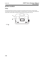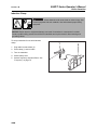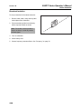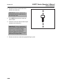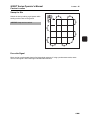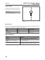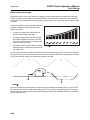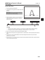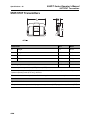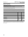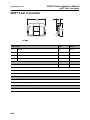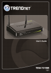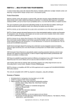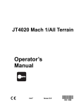
1
900R/T Series
Operator’s
Manual
CMW®
Issue 3.0
053-1118
900R/T Series Manual
Overview - 1
Overview
Chapter Contents
Serial Number Location . . . . . . . . . . . . . . . . . . . . . . 2
Intended Use . . . . . . . . . . . . . . . . . . . . . . . . . . . . . . 3
About This Manual . . . . . . . . . . . . . . . . . . . . . . . . . . 4
•
Bulleted Lists . . . . . . . . . . . . . . . . . . . . . . . . . . . . . . . . . . . . . . . . . . . . . .4
•
Numbered Lists . . . . . . . . . . . . . . . . . . . . . . . . . . . . . . . . . . . . . . . . . . . .4
FCC Statement . . . . . . . . . . . . . . . . . . . . . . . . . . . . . 4
IEC Safety Definitions . . . . . . . . . . . . . . . . . . . . . . . 4
CMW
900R/T Series Operator’s Manual
Overview - 2
Serial Number Location
Serial Number Location
Record serial numbers and date of purchase in spaces provided. Unit serial number is located as shown.
Item
date of purchase:
receiver serial number:
transmitter serial number:
fault finder serial number:
accessory model & serial number:
accessory model & serial number:
CMW
900R/T Series Manual
Overview - 3
Intended Use
Intended Use
The 950R receiver is designed to locate buried pipes and cables. Several frequencies and modes of
operation are available to suit your specific locating needs. The 910R receiver is a configurable version of
the 950R. Unit will not have all options described due to configuration ordered.
•
Available passive modes include 50Hz, 50P, 60 Hz, 100 Hz, 120 Hz and 60P power, radio, and 31 kHz
CATV. CP1, CP2, CP3, CP4, CP5, and CP6 modes are available for searching for cables with cathodic
protection.
•
Available active modes include 512 Hz, 1 kHz, 8 kHz, 29 kHz, 80 kHz, and 200 kHz for use with Ditch
Witch transmitters. 273 Hz, 400 Hz, 560 Hz, 815 Hz, 8.1 kHz, 33 kHz, and 100 kHz modes also are
available with the 950R, but are not transmitted by the 950T, 970T or 980T.
•
Available beacon modes include 512 Hz, 640 Hz, 29 kHz, and 33 kHz for locating non-metallic pipes.
The 950T and 970T transmitters place signals on target cables to be detected by 900 series receivers.
Both units can be configured to send 512 Hz, 1 kHz, 8 kHz, 29 kHz, 80 kHz, and dual (8 kHz and 29 kHz)
frequencies. The 970T can also be configured to transmit 200 kHz. Both transmitters place a signal on the
cable through either direct connection, induction clamping, or broadcast modes.
The 980T transmitter places signals on target cables to be detected by 900 series receivers or 980SFP
fault finders. The unit can be configured to send 512 Hz, 1 kHz, 8 kHz, 29 kHz and 80 kHz frequencies. It
also transmits fault location signals. The transmitter places a signal on the cable through either direct
connection, induction clamping, broadcast or fault finding modes.
The 980SFP fault finder is designed to locate fault signals generated by the FT12, FT14, 980T or 980FT
transmitter in de-energized cables that are disconnected on both ends.
The 980FT transmitter places fault detection signals on target cables to be detected by 980SFP fault
finders.
The system is designed for operation in temperatures typically experienced in earth moving and
construction work environments. Use in any other way is considered contrary to the intended use. The 900
series system should be operated only by persons familiar with its particular characteristics and acquainted
with the relevant safety procedures. The system should be serviced only by Ditch Witch repair centers.
CMW
Overview - 4
900R/T Series Operator’s Manual
About This Manual
About This Manual
This manual contains information for the proper use of this equipment. Cross references such as “See
page 50” will direct you to detailed procedures.
Bulleted Lists
Bulleted lists provide helpful or important information or contain procedures that do not have to be
performed in a specific order.
Numbered Lists
Numbered lists contain illustration callouts or list steps that must be performed in order.
FCC Statement
This device complies with Part 15 of the FCC Rules. Operation is subject to the following two conditions:
(1) this device may not cause harmful interference, and (2) this device must accept any interference
received, including interference that may cause undesired operation.
Changes or modifications not expressly approved by The Charles Machine Works, Inc. could void the
user’s authority to operate the equipment.
This equipment has been tested and found to comply with the limits for a Class A digital device, pursuant
to Part 15 of the FCC Rules. These limits are designed to provide reasonable protection against harmful
interference when the equipment is operated in a commercial environment. This equipment generates,
uses, and can radiate radio frequency energy and, if not installed and used in accordance with the
operator’s manual, may cause harmful interference to radio communications. Operation of this equipment
in a residential area is likely to cause harmful interference in which case the user will be required to correct
the interference at his own expense.
IEC Safety Definitions
Hazardous voltage--electrical shock or equipment damage can result if transmitter is connected to
live cable. Have qualified utility personnel disconnect both ends of cable before working.
IEC protection class II or double insulated electrical device is one which has been designed in
such a way that it does not require a safety connection to electrical ground. In a device of this
class, no single failure can result in dangerous voltage becoming exposed so that it might cause
an electrical shock. This characteristic must be achieved without relying on a grounded metal
casing.
CMW
900R/T Series Manual
Foreword - 5
Foreword
This manual is an important part of your equipment. It provides safety information and operation
instructions to help you use and maintain your Ditch Witch equipment.
Read this manual before using your equipment. Keep it with the equipment at all times for future reference.
If you sell your equipment, be sure to give this manual to the new owner.
If you need a replacement copy, contact your Ditch Witch dealer. If you need assistance in locating a
dealer, visit our website at www.ditchwitch.com or write to the following address:
The Charles Machine Works, Inc.
Attn: Marketing Department
PO Box 66
Perry, OK 73077-0066
USA
The descriptions and specifications in this manual are subject to change without notice. The Charles
Machine Works, Inc. reserves the right to improve equipment. Some product improvements may have
taken place after this manual was published. For the latest information on Ditch Witch equipment, see your
Ditch Witch dealer.
Thank you for buying and using Ditch Witch equipment.
CMW
Foreword - 6
900R/T Series Operator’s Manual
900R/T Series
Operator’s Manual
Issue number 3.0/OM-4/09
Part number 053-1118
Copyright 2007, 2008, 2009
by The Charles Machine Works, Inc.
, Ditch Witch, CMW, AutoCrowd, Modularmatic, Jet Trac, Roto Witch, Subsite,
Fluid Miser, Perma-Soil, Power Pipe, Super Witch, Super Witch II, Pierce Airrow, The Underground, and
The Underground Authority Worldwide are registered trademarks of The Charles Machine Works, Inc.
CMW
900R/T Series Operator’s Manual
Contents - 7
Contents
Overview
1
machine serial number, information about the type of work this machine is designed
to perform, basic machine components, and how to use this manual
Foreword
5
part number, revision level, and publication date of this manual, and factory contact
information
Safety
9
machine safety alerts and emergency procedures
Controls
15
machine controls and how to use them
Locate
45
procedures for locating active, passive and beacon signals
Locating Concepts
69
basic information for locating active, passive and beacon signals
Service
77
service intervals and instructions for this machine
Specifications
81
machine specifications including weights, measurements and power rating
Support
87
the warranty policy for this machine, and procedures for obtaining warranty
consideration and training
CMW
Contents - 8
CMW
900R/T Series Operator’s Manual
900R/T Series Operator’s Manual
Safety - 9
Safety
Chapter Contents
Guidelines . . . . . . . . . . . . . . . . . . . . . . . . . . . . . . . . 10
Safety Alert Classifications . . . . . . . . . . . . . . . . . . 11
Safety Alerts . . . . . . . . . . . . . . . . . . . . . . . . . . . . . . 12
CMW
Safety - 10
900R/T Series Operator’s Manual
Guidelines
Guidelines
Follow these guidelines before operating any jobsite equipment:
•
Complete proper training and read operator’s manual before using equipment.
•
Contact your local One-Call (811 in USA) or the One-Call referral number (888-258-0808 in USA and
Canada) to have underground utilities located before working. Also contact any utilities that do not
participate in the One-Call service.
•
Classify jobsite based on its hazards and use correct tools and machinery, safety equipment, and work
methods for jobsite.
•
Mark jobsite clearly and keep spectators away.
•
Wear personal protective equipment.
•
Review jobsite hazards, safety and emergency procedures, and individual responsibilities with all
personnel before work begins.
•
Replace missing or damaged safety signs.
•
Use equipment carefully. Stop operation and investigate anything that does not look or feel right.
•
Contact your equipment dealer if you have any question about operation, maintenance, or equipment
use.
CMW
900R/T Series Operator’s Manual
Safety - 11
Safety Alert Classifications
Safety Alert Classifications
These classifications and the icons defined on the following pages work together to alert you to situations
which could be harmful to you, jobsite bystanders or your equipment. When you see these words and
icons in the book or on the unit, carefully read and follow all instructions. YOUR SAFETY IS AT STAKE.
Watch for the three safety alert levels: DANGER, WARNING and CAUTION. Learn what each level
means.
indicates an imminently hazardous situation which, if not avoided, will result in death or
serious injury.
indicates a potentially hazardous situation which, if not avoided, could result in death or
serious injury.
indicates a potentially hazardous situation which, if not avoided, may result in minor or
moderate injury.
Watch for two other words: NOTICE and IMPORTANT.
NOTICE can keep you from doing something that might damage the unit or someone's property. It can also
alert you against unsafe practices.
IMPORTANT can help you do a better job or make your job easier in some way.
CMW
900R/T Series Operator’s Manual
Safety - 12
Safety Alerts
Safety Alerts
Electric shock. Contacting electric lines will cause death or serious injury.
Know location of lines and stay away.
Jobsite hazards could cause death or serious injury. Use
correct equipment and work methods. Use and maintain proper safety
equipment.
Explosion possible. Serious injury or equipment damage could occur.
Follow directions carefully.
Incorrect procedures could result in death, injury, or property damage.
Learn to use equipment correctly.
Moving traffic - hazardous situation. Death or serious injury could result.
Avoid moving vehicles, wear high visibility clothing, post appropriate warning signs.
Potential radio frequency (RF) hazard. Operating this device within 4” (100
mm) of your body may cause RF exposure levels to exceed FCC RF exposure limits and
should be avoided.
CMW
900R/T Series Operator’s Manual
Safety - 13
Safety Alert
Safety Alert
Read and follow all safety precautions.
Do not operate equipment unless you have completed proper training and have read the operator’s
manual.
Check that equipment is in good condition and that test leads are clean and have no cracked insulation.
HIGH VOLTAGE. This device produces electric current that could cause
death or serious injury. Electric shock may result if you touch the clips on the HV output
cable. Use electrically insulating rubber gloves and proper procedures.
Electric shock or equipment damage can result if transmitter is connected to
live cable. Have qualified utility personnel disconnect both ends of cable before working.
Turn off transmitter when connecting or moving ground probe.
Jobsite hazards could cause death or serious injury. Use correct equipment and work methods. Use and
maintain proper safety equipment.
Explosion possible. Do not operate transmitter near explosive devices or
blasting operations.
CMW
Safety - 14
900R/T Series Operator’s Manual
Safety Alert
CMW
900R/T Series Operator’s Manual
Controls - 15
Controls
Chapter Contents
910R/950R Receivers . . . . . . . . . . . . . . . . . . . . . . . 16
•
Single-Key Controls . . . . . . . . . . . . . . . . . . . . . . . . . . . . . . . . . . . . . . . .16
•
Dual-Key Controls . . . . . . . . . . . . . . . . . . . . . . . . . . . . . . . . . . . . . . . . .18
•
Display . . . . . . . . . . . . . . . . . . . . . . . . . . . . . . . . . . . . . . . . . . . . . . . . . .20
950T Transmitter . . . . . . . . . . . . . . . . . . . . . . . . . . 23
•
Controls . . . . . . . . . . . . . . . . . . . . . . . . . . . . . . . . . . . . . . . . . . . . . . . . .23
•
Display . . . . . . . . . . . . . . . . . . . . . . . . . . . . . . . . . . . . . . . . . . . . . . . . . .25
970T Transmitter . . . . . . . . . . . . . . . . . . . . . . . . . . 27
•
Single-Key Controls . . . . . . . . . . . . . . . . . . . . . . . . . . . . . . . . . . . . . . . .27
•
Dual-Key Controls . . . . . . . . . . . . . . . . . . . . . . . . . . . . . . . . . . . . . . . . .29
•
Display . . . . . . . . . . . . . . . . . . . . . . . . . . . . . . . . . . . . . . . . . . . . . . . . . .30
980T Transmitter . . . . . . . . . . . . . . . . . . . . . . . . . . 32
•
Single-Key Controls . . . . . . . . . . . . . . . . . . . . . . . . . . . . . . . . . . . . . . . .32
•
Dual-Key Controls . . . . . . . . . . . . . . . . . . . . . . . . . . . . . . . . . . . . . . . . .34
•
Display . . . . . . . . . . . . . . . . . . . . . . . . . . . . . . . . . . . . . . . . . . . . . . . . . .35
980SFP Fault Finder . . . . . . . . . . . . . . . . . . . . . . . 38
980FT Fault Transmitter . . . . . . . . . . . . . . . . . . . . 40
CMW
900R/T Series Operator’s Manual
Controls - 16
910R/950R Receivers
910R/950R Receivers
Single-Key Controls
SINGLE
FT / IN
CM
TWIN
A
NULL
L/R
6
1
2
3
4
ss0003d.eps
1. MODE
4. Up arrow
2. DEPTH
5. ANT SEL
3. Down arrow
6. ON/OFF
Item
Description
1. MODE
To cycle through operating
frequencies, press.
si0007c-d.eps
CMW
Notes
5
900R/T Series Operator’s Manual
Controls - 17
910R/950R Receivers
Item
Description
2. DEPTH
To estimate depth of properly
located signal source, press.
Notes
To show amount of current on
the target cable in milliamps
(mA), press and hold.
si0008c-d.eps
3. Down Arrow
To decrease gain
incrementally from 20% to
80%, press.
If signal is above 80%, press once to
lower gain to approximately 50%.
To disable this feature:
1. Ensure that unit is off.
2. Press and hold the down arrow.
3. Turn unit on.
4. Up Arrow
To increase gain
incrementally from 20% to
80%, press.
If signal is below 20%, press once to
raise gain to approximately 50%.
To disable this feature:
1. Ensure that unit is off.
2. Press and hold the down arrow.
3. Turn unit on.
5. ANT SEL
To cycle through single, twin,
null, and left/right antenna
modes, press.
si0006c-d.eps
6. ON/OFF
To turn on, press.
To turn off, press again.
si0005c-d.eps
CMW
Controls - 18
900R/T Series Operator’s Manual
910R/950R Receivers
Double-Key Controls
Item
Description
DEPTH + ANT SEL
To turn on backlight, press indicated
keys.
ss0026c-d.eps
DEPTH + Up Arrow
To change volume, press indicated
keys.
ss0027c-d.eps
DEPTH + Down Arrow
To cycle through the units of
measurement in which the depth
displays (ft/in, in, cm, or m), press
indicated keys.
ss0028c-d.eps
DEPTH + MODE
To show percent of battery life
remaining, press indicated keys.
ss0029c-d.eps
DEPTH + ON/OFF
To cycle through audio output modes,
press indicated keys.
Audio
Output
Modes
ss0010d.eps
CMW
A-1 is the standard FM audio tone.
A-2 is an AM audio tone.
A-3 is a unique, mixed audio tone.
900R/T Series Operator’s Manual
Controls - 19
910R/950R Receivers
Item
Description
Down Arrow + ON/OFF
To select type of gain display, press
indicated keys while turning the
receiver on. Release ON/OFF key
before releasing down arrow key.
Selectable
Gain
ss0011d.eps
Normal (nor) gain display ranges from
1 to 80.
Automatic (Aut) gain display keeps
the gain between 40 and 60%.
Receiver will remain in selected mode
until operator changes it.
CMW
900R/T Series Operator’s Manual
Controls - 20
910R/950R Receivers
Display
1
2
4 5
3
SINGLE
FT / IN
CM
TWIN
9
6
A
NULL
L/R
7
8
ss0004d.eps
1. Volume level
6. Battery level
2. Gain level
7. Frequency
3. Signal strength
8. Mode
4. Depth
9. Antenna
5. Current
Item
Description
Notes
1. Volume Level
Indicates volume level.
IMPORTANT: Lower volume to
conserve battery life.
si0004h-d.cdr
CMW
900R/T Series Operator’s Manual
Controls - 21
910R/950R Receivers
Item
Description
Notes
2. Gain Level
Graphically indicates gain
level.
IMPORTANT: Gain increases to the
right.
3. Signal Strength
Numerically and graphically
indicates the signal strength
level.
4. Depth
Displays depth estimate of
properly located cable.
FT / IN
CM
ss0008c-d.eps
5. Current
6. Battery Level
ss0009c-d.eps
Displays current
measurement on properly
located cable.
IMPORTANT:
•
The higher the number, the higher
the current on target cable.
•
Current reading should be stable
or drop as cable is located, except
at ends where current is higher.
Indicates battery level.
•
Three segments indicates
full battery power.
•
One segment indicates
low power.
•
No segments and
flashing outline indicates
that batteries should be
changed immediately.
CMW
900R/T Series Operator’s Manual
Controls - 22
910R/950R Receivers
Item
Description
Notes
7. Frequency
Indicates frequency setting.
See “Frequency” on page 74.
Indicates mode setting.
See “Mode” on page 71.
Indicates antenna
configuration.
See “Antenna Configuration” on
page 73.
si0010c-d.eps
8. Mode
ss0002d.eps
9. Antenna
SINGLE
TWIN
NULL
L/R
ss0001d.eps
CMW
900R/T Series Operator’s Manual
Controls - 23
950T Transmitter
950T Transmitter
Controls
2
1
6
5
4
3
ss0005d.eps
1. Frequency
4. Power output up
2. On/Off
5. Power output down
3. Timer
6. Volume
Item
Description
Notes
1. Frequency
To cycle through available
frequencies, press.
See “Frequency” on page 74.
si0017c-d.eps
CMW
900R/T Series Operator’s Manual
Controls - 24
950T Transmitter
Item
Description
2. On/Off
To turn on, press.
To turn off, press again.
si1017a-d.eps
3. Timer
To set timer to one hour,
press.
To increase timer by one hour
(up to a maximum of 8 hours),
press again.
To run continuously, press
until display shows 0:00.
si0018c-d.eps
4. Power Output Up
To raise power output by
increments from minimum to
maximum, press.
si0015c-d.eps
5. Power Output Down
To lower power output by
increments from maximum to
minimum, press.
si0016c-d.eps
6. Volume
To turn volume on, press.
To turn volume off, press
again.
si0004h-d.cdr
CMW
Notes
900R/T Series Operator’s Manual
Controls - 25
950T Transmitter
Display
1
3
2
ss0006d.eps
1. Frequency
3. Power level
2. Timer
Item
Description
1. Frequency
Displays selected frequency.
Notes
si0010c-d.eps
2. Timer
Displays amount of time left
on timer.
si0020c-d.eps
CMW
900R/T Series Operator’s Manual
Controls - 26
950T Transmitter
Item
Description
Notes
3. Power Level
Displays selected power
level.
In direct connect and induction clamp
modes, a tone indicates satisfactory
connection.
In broadcast mode, a beeping tone
indicates that current is flowing from
transmitter.
CMW
900R/T Series Operator’s Manual
Controls - 27
970T Transmitter
970T Transmitter
Single-Key Controls
2
1
ss0007d.eps
6
5
4
3
1. Frequency
4. Power output up
2. On/Off
5. Power output down
3. Timer
6. 2nd
Item
Description
Notes
1. Frequency
To cycle through available
frequencies, press.
See “Frequency” on page 74.
si0017c-d.eps
CMW
900R/T Series Operator’s Manual
Controls - 28
970T Transmitter
Item
Description
2. On/Off
To turn on, press.
Notes
To turn off, press again.
si1017a-d.eps
3. Timer
To set timer to one hour,
press.
To increase timer by one hour
(up to a maximum of 8 hours),
press again.
To run continuously, press
until display shows 0:00.
si0018c-d.eps
4. Power Output Up
To raise power output by
increments from minimum to
maximum, press.
si0015c-d.eps
5. Power Output Down
To lower power output by
increments from maximum to
minimum, press.
si0016c-d.eps
6. 2nd
2ND
si0017h-d.eps
CMW
Allows access to 2nd key
functions.
See “Double-Key Controls” on
page 29.
900R/T Series Operator’s Manual
Controls - 29
970T Transmitter
Double-Key Controls
Item
Description
2nd + Power Output Down
To change volume, press indicated
keys.
ss0031c-d.eps
2nd + Timer
To turn on backlight, press indicated
keys.
Turn turn backlight off, press
indicated keys again.
ss0032c-d.eps
2nd + Frequency
To see current in milliamps, press
indicated keys once.
To see voltage generated by
transmitter, press indicated keys
again.
ss0033c-d.eps
To display voltage on cable, press
indicated keys again.
To see resistance in ohms, press
indicated keys again.
CMW
900R/T Series Operator’s Manual
Controls - 30
970T Transmitter
Display
1
3
2
ss0008d.eps
1. Frequency
3. Power level
2. Timer
Item
Description
1. Frequency
Displays selected frequency.
si0010c-d.eps
2. Timer
si0020c-d.eps
CMW
Displays amount of time left
on timer.
Notes
900R/T Series Operator’s Manual
Controls - 31
Item
Description
Notes
3. Power Level
Displays selected power
level.
In direct connect and induction clamp
modes, a tone indicates satisfactory
connection.
In broadcast mode, a beeping tone
indicates that current is flowing from
transmitter.
CMW
900R/T Series Operator’s Manual
Controls - 32
980T Transmitter
980T Transmitter
Single-Key Controls
1. Frequency
4. Power output up
2. On/Off
5. Power output down
3. Timer
6. 2nd
Item
Description
Notes
1. Frequency
To cycle through available
frequencies, press.
See “Frequency” on page 74.
si0017c-d.eps
CMW
900R/T Series Operator’s Manual
Controls - 33
980T Transmitter
Item
Description
Notes
2. On/Off
To turn on, press.
IMPORTANT: If fault leads are
connected when unit is turned on,
transmitter will display dashes (---).
Press power output up key to finish
turning on the unit.
To turn off, press again.
si1017a-d.eps
3. Timer
To set timer to one hour,
press.
To increase timer by one hour
(up to a maximum of 8 hours),
press again.
To run continuously, press
until display shows 0:00.
si0018c-d.eps
4. Power Output Up
To raise power output by
increments from minimum to
maximum, press.
To complete entry into fault mode,
press key after power up.
si0015c-d.eps
5. Power Output Down
To lower power output by
increments from maximum to
minimum, press.
si0016c-d.eps
6. 2nd
Allows access to 2nd key
functions.
See “Double-Key Controls” on
page 34.
2ND
si0017h-d.eps
CMW
Controls - 34
900R/T Series Operator’s Manual
980T Transmitter
Double-Key Controls
Item
Description
2nd + Power Output Down
To change volume, press indicated
keys.
ss0031c-d.eps
2nd + Timer
To turn on backlight, press indicated
keys.
Turn turn backlight off, press
indicated keys again.
ss0032c-d.eps
2nd + Frequency
To see current in milliamps, press
indicated keys once.
To see voltage generated by
transmitter, press indicated keys
again.
ss0033c-d.eps
To display voltage on cable, press
indicated keys again.
To see resistance in ohms, press
indicated keys again.
CMW
900R/T Series Operator’s Manual
Controls - 35
980T Transmitter
Display
1. Battery level
5. Timer
2. Backlight indicator
6. Dual frequency indicator
3. Volume indicator
7. Power level/impedence indicator
4. Frequency
Item
Description
1. Battery Level
Indicates battery level.
ss0009c-d.eps
•
Three segments indicates
full battery level.
•
One segment indicates
low level.
•
No segments indicates
that batteries should be
changed soon.
Notes
CMW
900R/T Series Operator’s Manual
Controls - 36
980T Transmitter
Item
Description
2. Backlight Indicator
Indicates backlight is on.
3. Volume Indicator
Indicates volume is on.
4. Frequency
Displays selected frequency.
si0010c-d.eps
5. Timer
Displays amount of time left
on timer.
si0020c-d.eps
6. Dual Frequency
Indicator
CMW
Indicates unit is in dual
frequency mode.
Notes
900R/T Series Operator’s Manual
Controls - 37
Item
Description
Notes
7. Power Level/
Impedence Indicator
Displays selected power level
when unit is in locating mode.
In direct connect and induction clamp
locating, a tone indicates satisfactory
connection.
Displays fault impedence
when in fault mode.
In broadcast locating, a beeping tone
indicates that current is flowing from
transmitter.
CMW
900R/T Series Operator’s Manual
Controls - 38
980SFP Fault Finder
980SFP Fault Finder
1. Battery level indicator
4. Fault direction indicator
2. Transmitter pulse indicator
5. Backlight key
3. Signal strength indicator
6. On/Off key
Item
Description
1. Battery level indicator
Displays battery charge.
2. Transmitter pulse
indicator
CMW
•
Solid indicates full
charge.
•
3/4 solid indicates good
charge.
•
1/4 solid indicates low
charge.
•
Flashing outline indicates
batteries need to be
changed.
Appears for 1/2 second when
pulse is detected.
Notes
900R/T Series Operator’s Manual
Controls - 39
980SFP Fault Finder
Item
Description
3. Signal strength
indicator
Displays signal strength when
signal is present.
4. Fault direction indicator
5. Backlight key
•
Below 40 indicates weak
signal.
•
40-59 indicates good
signal.
•
60 and higher indicates
strong signal.
Notes
Points toward the fault when
signal is present.
•
Three arrows indicate
strong signal.
•
Two arrows indicate good
signal.
•
One arrow indicates
weak signal.
•
Hollow arrow indicates
noise.
Press to toggle backlight on
and off.
c00ic544h.eps
6. On/Off key
Press to turn on and off.
si1017a-d.eps
CMW
900R/T Series Operator’s Manual
Controls - 40
980FT Fault Transmitter
980FT Fault Transmitter
Controls
1M
0K 00K 50K 10K
1
50
5K
2K
1K 500 500
<
UNLOCK
5
4
3
1
2
e13om002h eps
1. On/Off key
4. Backlight key
2. Timer key
5. Volume key
3. Unlock key
Item
Description
Notes
1. On/Off Key
To turn on, press.
IMPORTANT: If fault leads are
connected when unit is turned on,
transmitter will display dashes (---).
Press unlock key to finish turning on
the unit.
To turn off, press again.
si1017a-d.eps
CMW
900R/T Series Operator’s Manual
Controls - 41
980FT Fault Transmitter
Item
Description
2. Timer Key
To set timer to one hour,
press.
Notes
To increase timer by one hour
(up to a maximum of 8 hours),
press again.
To run continuously, press
until display shows 0:00.
si0018c-d.eps
3. Unlock Key
Press to finish entry into fault
mode after fault leads are
connected.
4. Backlight key
Press to toggle backlight on
and off.
c00ic544h.eps
5. Volume
To turn volume on, press.
To turn volume off, press
again.
si0004h-d.cdr
CMW
900R/T Series Operator’s Manual
Controls - 42
980FT Fault Transmitter
Display
4
5
3
2
1
1M
0K 00K 50K 10K
1
50
5K
2K
1K 500 500
<
UNLOCK
1. Battery level
4. Timer
2. Backlight indicator
5. Impedence indicator
3. Volume indicator
Item
Description
1. Battery Level
Indicates battery level.
ss0009c-d.eps
2. Backlight Indicator
CMW
•
Three segments indicates
full battery level.
•
One segment indicates
low level.
•
No segments indicates
that batteries should be
changed soon.
Indicates backlight is on.
Notes
900R/T Series Operator’s Manual
Item
Description
3. Volume Indicator
Indicates volume is on.
4. Timer
Displays amount of time left
on timer.
Controls - 43
Notes
si0020c-d.eps
5. Impedence Indicator
Displays fault impedence.
CMW
Controls - 44
CMW
900R/T Series Operator’s Manual
900R/T Series Operator’s Manual
Locate - 45
Locate
Chapter Contents
Active . . . . . . . . . . . . . . . . . . . . . . . . . . . . . . . . . . . 46
•
Setup. . . . . . . . . . . . . . . . . . . . . . . . . . . . . . . . . . . . . . . . . . . . . . . . . . . .46
•
Technique . . . . . . . . . . . . . . . . . . . . . . . . . . . . . . . . . . . . . . . . . . . . . . . .51
•
Special Situations . . . . . . . . . . . . . . . . . . . . . . . . . . . . . . . . . . . . . . . . . .53
Passive . . . . . . . . . . . . . . . . . . . . . . . . . . . . . . . . . . 54
•
Setup. . . . . . . . . . . . . . . . . . . . . . . . . . . . . . . . . . . . . . . . . . . . . . . . . . . .54
•
Technique . . . . . . . . . . . . . . . . . . . . . . . . . . . . . . . . . . . . . . . . . . . . . . . .54
•
Special Situations . . . . . . . . . . . . . . . . . . . . . . . . . . . . . . . . . . . . . . . . . .56
Beacon . . . . . . . . . . . . . . . . . . . . . . . . . . . . . . . . . . 57
•
Setup. . . . . . . . . . . . . . . . . . . . . . . . . . . . . . . . . . . . . . . . . . . . . . . . . . . .57
•
Technique . . . . . . . . . . . . . . . . . . . . . . . . . . . . . . . . . . . . . . . . . . . . . . . .57
Fault Finding . . . . . . . . . . . . . . . . . . . . . . . . . . . . . 58
•
Background . . . . . . . . . . . . . . . . . . . . . . . . . . . . . . . . . . . . . . . . . . . . . .58
•
Technique . . . . . . . . . . . . . . . . . . . . . . . . . . . . . . . . . . . . . . . . . . . . . . . .59
CMW
Locate - 46
900R/T Series Operator’s Manual
Active Location
Active Location
Setup
Follow setup procedures for the type of locating you will be doing: direct connection, induction clamp,
connecting to live power with live power adapter, or broadcast induction. For all types of active location that
require leads, connect leads at connector (2). Keep connector covered when not in use.
CMW
900R/T Series Operator’s Manual
Locate - 47
Active Location
Direct Connection
Jobsite hazards could cause death or serious injury. Use
correct equipment and work methods. Use and maintain proper safety
equipment.
NOTICE:
•
Electric shock or equipment damage can result if transmitter is connected to live cable. Contact
qualified utility personnel and follow all standards and requirements for disconnecting and grounding
cables.
•
A built-in circuit breaker will automatically disable transmitter when leads are connected to a live
cable. Display will flash and transmitter will beep. Turn off transmitter and disconnect from cable to
reset breaker.
To set up transmitter for direct connection:
1
2
3
ss0014c-d.eps
1. Carefully push ground stake (3) into ground.
2. Plug cable into transmitter (2).
3. Connect black lead to ground stake.
4. Connect red lead to cable (1).
5. Turn on transmitter and check battery level.
6. Choose frequency and shutoff time. See “Frequency” on page 74.
NOTICE: Turn off transmitter when connecting or moving ground stake.
CMW
900R/T Series Operator’s Manual
Locate - 48
Active Location
Induction Clamp
Jobsite hazards could cause death or serious injury. Use
correct equipment and work methods. Use and maintain proper safety
equipment.
NOTICE: Electric shock or equipment damage can result if transmitter is connected to live cable.
Contact qualified utility personnel and follow all standards and requirements for disconnecting and
grounding cables.
To set up transmitter for use with induction
clamp:
1
1. Plug cable into transmitter (2).
2. Place clamp (1) around cable.
3. Turn on transmitter.
4. Check battery level.
5. Choose frequency and shutoff time. See
“Frequency” on page 74.
ss0016c-d.eps
CMW
2
900R/T Series Operator’s Manual
Locate - 49
Active Location
Connecting to Live Power with Live Power Adapter
Jobsite hazards could cause death or serious injury. Use
correct equipment and work methods. Use and maintain proper safety
equipment.
NOTICE:
•
Do not operate equipment unless you are properly qualified to work on live power conductors.
•
Use personal protective equipment rated for voltage and current of power conductor being
connected to as defined by OSHA standards when using live power adapter.
•
Do not connect to a conductor with a voltage greater than 480V.
To set up transmitter for use with live power adapter:
1. Verify that transmitter (1) is turned off.
2. Connect live power adapter (2) to the transmitter.
3. Connect live power adapter black lead to the ground stake (4).
4. Connect live power adapter red lead to live power conductor (3).
5. Turn on transmitter.
6. Select frequency greater than 8 kHz (29 kHz is preferred).
7. Adjust power level as needed.
8. Check battery level.
IMPORTANT: When finished locating the cable, turn off transmitter, disconnect live power adapter red
lead from live power conductor, disconnect live power adapter black lead from ground stake, and
disconnect live power adapter from transmitter.
CMW
Locate - 50
900R/T Series Operator’s Manual
Active Location
Broadcast Induction
To set up transmitter for broadcast induction:
1. Remove cable, stake, clamp and any other
metal objects from transmitter.
2. Place transmitter parallel to and directly
above suspected cable as shown.
Note: Transmitter must be parallel to
object, as shown, in order to produce
the best signal.
ss0017c-d.eps
3. Turn on transmitter.
4. Check battery level.
5. Choose frequency and shutoff time. See “Frequency” on page 74.
CMW
900R/T Series Operator’s Manual
Locate - 51
Active Location
Technique
IMPORTANT: Follow steps 1-3 for all types of active location. For reference, the illustration above
shows direct connection method. If using broadcast induction, ensure that transmitter is in line with and
above suspected cable, as shown on previous page.
1. Walk in an arc approximately 25’ (7.5 m) around transmitter.
2. Hold the receiver so that the handle points toward the transmitter, as shown.
3. Identify location of cable by finding the spot with the best signal response.
CMW
Locate - 52
900R/T Series Operator’s Manual
Active Location
4. Rotate the receiver to determine which
direction the cable runs.
IMPORTANT: Receiver indicates the
best signal when the handle lines up
with the target cable.
5. Press DEPTH key when the cable has
been located.
6. Continue to trace the cable and take depth
estimates every few paces.
IMPORTANT: Current measurement
can be used as a cable identifier when
transmitter is connected to target
cable. Current on the target cable
should be higher that current on
another cable that is picking up signal
inductively from target cable.
ss1080a-d.eps
7. Retrace the cable and mark with appropriate flags or paint.
CMW
900R/T Series Operator’s Manual
Locate - 53
Active Location
Mark the Cable
Sweep, focus, and trace all detected signals in the area. Mark cable paths with colored paint or flags. See
the chart below for standard color markings for cable locations.
Utility
Color
Marking Symbol
electric
red
-E-
gas/oil
yellow
-G-
communications
orange
-TEL- or -TV-
water
blue
-W-
sewer
green
-S-
Special Situations
Situation
What to try
Signal is lost.
Walk in a circle to detect a tee or bend in the cable.
Signal varies from low to high and is
unstable.
Mark as a hand-dig area.
You are near a power line and are
receiving interference.
Sweep the area in 50 Hz or 60 Hz power mode. If receiver
gives a strong signal response, a power line is interfering
with transmitter signal.
Receiver does not function properly.
Receiver gain could be set too high or low. Lower or raise
gain to locate the cable. See “Controls” on page 15.
Target cable has connections to other
cables.
Disconnect target cable from other cables or use direct
connect or induction clamp to focus signal on target cable.
Signal is transferring to other cables.
•
Lower the frequency.
•
Lower the power level.
•
Use direct connection, if possible, or use induction
clamp.
•
Move the ground stake away from the target cable and
away from other buried cables.
•
Apply signal at the point where the target cable is
farthest from the other cables.
CMW
Locate - 54
900R/T Series Operator’s Manual
Passive Location
Passive Location
Setup
Follow setup procedures for the type of locating you will be doing. Always check receiver battery level at
startup. See “Controls” on page 15.
NOTICE: Cables with no A/C current flowing through them are hard to detect and may be hazardous
because they may still have voltage potential. To locate, turn on an appliance to cause current to flow
and use active search methods.
Technique
Survey the Site
Make a visual check of the site for signs of buried cables such as:
•
recent trenching
•
buried cable markers
•
overhead lines that run down pole and underground
•
gas meters
•
valve sights
•
drains or manhole covers
CMW
900R/T Series Operator’s Manual
Locate - 55
Passive Location
Sweep the Site
Search the site by walking a grid pattern while
holding receiver close to the ground.
NOTICE: Keep receiver vertical.
ss1076a-d.eps
Focus the Signal
Move receiver over detected signal to find best signal response. If using a peak antenna mode, rotate
receiver until signal is best. Best signal indicates cable direction.
CMW
900R/T Series Operator’s Manual
Locate - 56
Passive Location
Trace the Cable
Walk along the suspected path while moving
the receiver from side to side across the area.
IMPORTANT: Keep receiver handle parallel
to the suspected cable path.
ss1080a-d.eps
Mark the Cable
Sweep, focus, and trace all detected signals in the area. Mark cable paths with colored paint or flags. See
the chart below for standard color markings for cable locations.
Utility
Color
Marking Symbol
electric
red
-E-
communications
orange
-TEL- or -TV-
Special Situations
Situation
What to try
Signal is lost.
Walk in a circle to detect a tee or bend in the cable.
Signal varies from low to high and is
unstable.
Mark as a hand-dig area.
Receiver does not function properly.
Receiver gain could be set too high or low. Lower or raise
gain to locate the cable. See “Controls” on page 13.
CMW
900R/T Series Operator’s Manual
Locate - 57
Beacon Location
Beacon Location
Trace metallic pipes or conduits by locating and following a beacon signal.
IMPORTANT: Large metal objects and other signals (such as railroad signals or overhead power lines)
will distort signal.
Setup
To set up for beacon location:
1. Follow instructions for installing beacon battery.
2. Turn on receiver to ensure that beacon is functioning properly.
3. Attach beacon to plumber’s snake or flex rod.
Technique
1. Turn on receiver.
2. Set antenna configuration and signal
source, and select beacon frequency.
3. Place beacon into the pipe and move it
down the pipe.
4. To locate beacon, circle over its
approximate location in the pipe.
5. To identify the location of beacon, find the
spot with the strongest signal response.
6. Rotate the receiver to determine which
direction beacon runs.
ss1081a-d.eps
IMPORTANT: Receiver indicates the best signal when handle is perpendicular to the beacon.
7. Press DEPTH key.
NOTICE: When estimating depth with a beacon in nonmetallic pipe, depth shown will be to the
center of the beacon, not to the top of the pipe.
8. Continue to track the beacon and take depth readings. Mark pipe location with paint.
CMW
Locate - 58
900R/T Series Operator’s Manual
Fault Finding
Fault Finding
Background
How Earth Return Faults Are Created
When a direct-buried cable’s insulation is damaged, the conductor is exposed to contact with the earth
which creates a fault. If large enough, the fault can degrade the service provided by the cable. This type of
fault is called an earth return fault. These damaged areas interact with the earth which causes corrosion
that can further degrade the service.
Faults can be caused by a number of actions.
•
Splicing: Corroded or damaged splices may fault to ground.
•
Excavation: Cables can be nicked or broken by excavation equipment such as shovel, backhoe,
trencher, drill head, auger, fence post, etc. These nicked areas can fault to ground and provide a place
for corrosion to start.
•
Abrasion: Rocks and other abrasive elements can damage cable when the earth shifts due to soil
conditions, climate and above-ground traffic.
IMPORTANT: Although there are other types of faults, only earth return faults can be detected with type
of equipment.
Finding General Location of a Faulted Cable
Some things to look for when searching for the general location of a faulted cable are:
•
recently disturbed soil
•
past splices
•
“buried utility” notices
•
utility facilities without overhead lines
•
junction boxes
•
drop boxes
•
light poles
•
sunken ground
CMW
900R/T Series Operator’s Manual
Locate - 59
Fault Finding
Technique
HIGH VOLTAGE. This device produces electric current that could cause
death or serious injury. Electric shock may result if you touch the clips on the HV output
cable. Use electrically insulating rubber gloves and proper procedures.
To enter fault location mode,
1. Connect fault leads at connector (1).
2. Press On/Off key or cycle power.
3. Press Unlock key (3).
IMPORTANT:
•
Keep connector covered when not in use.
•
Connector (2) is only on 980T.
Setup
Set up transmitter to locate earth return faults by following this procedure:
1. De-energize and disconnect the cable at both ends.
2. Push ground stake (2) into soil inline with the cable and as far away from transmitter as possible.
3. Connect one lead of the transmitter to the ground stake and connect the other lead to one end of the
cable (3).
4. Turn on fault transmitter (1) by pressing on/off key and then unlock key.
CMW
Locate - 60
900R/T Series Operator’s Manual
Fault Finding
Fault Locating Concepts
Isolating the cable on both ends and then engergizing it with a special signal generated by a transmitter
creates an electrical circuit where current flows down the cable and seeks a path back to the transmitter.
The path back to the transmitter is along the path of the fault to ground. Current will not flow without a path
to ground.
After the transmitter is connected to the cable, the
impedance reading will help verify that a fault
exists on the cable.
•
A reading of greater than 1M indicates no
significant fault exists in the cable.
•
A reading between 500K and 50K indicates
that a high-resistance fault exists. This fault
may not yet cause problems but it will worsen
over time due to corrosion.
•
A reading of less than 50K indicates a heavy
fault that is likely to affect the performance of
the cable exists.
Use an A-frame detector to probe the earth and measure the signal along the path of the cable. Signal will
be highest at the point of the fault where the current enters the ground and at the transmitter ground stake.
The A-frame detector arrows point toward the direction of the fault.
As you move away from the transmitter, detector may stop indicating transmitter pulses. As you near the
fault, detector will resume indicating transmitter pulses. This is normal. Transmitter pulses are strongest
near the point of the fault (X) and at the transmitter ground. When probes straddle the fault or transmitter
ground, signal will drop.
CMW
900R/T Series Operator’s Manual
Locate - 61
Fault Finding
Known Cable Route
1. Set up transmitter (see page 59).
2. Insert detector in the ground in line with cable route
(shown).
IMPORTANT: Take hands off detector once it is
in the ground for a clearer reading.
3. When transmitter sends out a pulse, detector will
display signal strength and direction if sufficient
signal is present.
•
If signal is weak, detector may take up to 20 seconds to stabilize before displaying reading.
•
If no signal is detected, detector will display a rotating indicator in center of screen.
4. Move 10’ (3 m) down the cable route and insert detector again.
5. After detector arrows point in the opposite direction, insert detector a few feet (meters) back down the
cable.
6. Repeat step 5 moving smaller distances until arrow changes direction after only a few inches
(millimeters) of movement.
7. Rotate detector 90° and repeat location process until arrow switches direction after a small movement.
Fault is directly between probes.
CMW
Locate - 62
900R/T Series Operator’s Manual
Fault Finding
Unknown Cable Route
IMPORTANT: If possible, locate the cable with a receiver and mark the location. Then follow the
instructions in “Known Cable Route” on page 61.
1. Draw a straight line between the two disconnected ends (1, 4) of the isolated cable.
2. Follow the instructions in “Known Cable Route” on page 61.
3. Once fault is found (2) on straight line, turn detector 90° and find true location of fault (3).
CMW
900R/T Series Operator’s Manual
Locate - 63
Fault Finding
Using Remote Probe
The remote probe is an extension of the A-frame detector’s red probe. It can extend the separation of the
detector probes from 2’/0.6 m (A) to over 20’/6 m (B). This increases the sensitivity of the detector and
allows probes to span obstacles such as sidewalks or streets.
Electric shock. Contacting electric lines will cause death or serious injury.
Know location of lines and stay away.
NOTICE: Do not connect transmitter to live cable. Have qualified utility personnel
disconnect cable at both ends.
1. Push detector into the ground on one side of the obstacle with red probe nearest obstacle.
2. Insert remote probe plug into remote probe jack under detector housing.
3. Clip other end of remote probe cable onto remote probe and push remote probe into the ground on the
other side of obstacle and in the direction nearer the detector’s red probe. The detector’s red probe is
automatically disabled when remote probe is connected.
IMPORTANT: If remote probe is pushed into the ground in the direction nearer the detector’s black
probe, arrows will point the wrong direction.
4. Turn on detector.
CMW
Locate - 64
900R/T Series Operator’s Manual
Fault Finding
5. After remote probe is in place, use detector arrows to determine which device needs to be moved
away from the obstacle.
•
If arrows point toward detector side of obstacle, move detector.
•
If arrows point toward remote probe side, move remote probe.
6. Continue to adjust position of the device moved in step 5 as indicated by the arrows.
7. Once fault is found using “Known Cable Route” on page 61, the actual location of the fault is halfway
between the black probe and the remote probe.
8. When remote probe is no longer needed, remove remote probe plug from detector housing. This will
enable the detector’s built-in red probe.
CMW
900R/T Series Operator’s Manual
Locate - 65
Fault Finding
Special Situations
Electric shock. Contacting electric lines will cause death or serious injury.
Know location of lines and stay away.
NOTICE: Do not connect transmitter to live cable. Have qualified utility personnel disconnect cable at
both ends.
Locating Fault at Meter Riser
If fault is suspected to be at or very near meter riser, try
one of the methods outlined below.
1. Turn detector (1) at a 45° angle to the house and
check for lowest reading along an imaginary line.
Take at least two readings. A low reading across a
line pointed at the meter riser (3) indicates a fault at
the base of or in the meter riser.
2. Connect transmitter to far end of the cable and
locate as usual toward the house. This method may
not be practical for long cable runs.
Locating Fault at Street Light Circuit
Have qualified utility personnel disconnect the ballast of the street light before locating fault. The ballast
distorts the transmitter pulse. Once the ballast is disconnected, locate fault as usual.
CMW
Locate - 66
900R/T Series Operator’s Manual
Fault Finding
Locating Fault in Shielded Conductor
NOTICE: Always turn off transmitter when connecting or moving ground probe.
This system is most effective in locating faults on direct-buried, grounded faults because the transmitter
pulse is allowed to travel to ground at the point of the fault. This is not always true with direct-buried,
shielded conductors. To locate a fault in a shielded conductor, use one of the methods outlined below.
Extend Transmitter Ground
1
1. Strip both ends of a 100-300’ (30-90 m) piece of
insulated wire (3).
2
2. Attach black clip from transmitter (2) high voltage
output cable to one end of the wire. Insulate the
connection.
3
3. Attach other end of wire to ground probe.
4. Extend the high voltage output cable (now attached
to the insulated wire, 3) perpendicular to the route
of the buried cable (1) as far as practical (A) within
the 100-300’ (30-90 m) range.
A
e11om010h.eps
5. Push ground probe into the ground.
6. Turn on transmitter and check for pulses with detector.
7. If this is unsuccessful, move ground probe to other side of faulted cable.
Use Running Ground
2
1
1. Strip both ends of a roll of insulated wire (4).
2. Attach black clip from transmitter (2) high voltage
output cable to one end of the wire. Insulate the
connection.
B
4
3. Attach other end of wire to ground probe.
4. Extend wire 30-50’/10-15 m (B) perpendicular to
buried cable (1) and insert ground probe.
5. Extend reel of wire and insert ground probe parallel
to the buried cable.
e11om011h.eps
NOTICE: Always turn off transmitter before
moving ground probe.
CMW
900R/T Series Operator’s Manual
Locate - 67
Fault Finding
Locating Fault Under Snow or Frozen Ground
Frozen ground is a barrier to the transmitter pulse. To receive signal through frozen ground, drive spikes
through frozen ground and touch detector probes to them. For greater sensitivity and easier handling,
attach remote probe.
Locating Fault Over Asphalt or Cement (Wet Sponge Method)
NOTICE: Do not touch bare metal parts of equipment. Wear electrically-insulating rubber gloves.
In paved areas where probes cannot be inserted into the ground such as parking lots or driveways, you
can use wet sponge method.
1. Mix 1 cup (236 mL) of salt with 1 gal (3.8 L) of water.
2. Soak two large sponges in the solution.
3. Place sponges about 10’ (3 m) apart on paved surface.
4. Attach remote probe to detector if greater sensitivity is needed.
5. Touch black probe to one sponge and remote probe to the other sponge.
6. Locate fault as usual, resoaking sponges often.
CMW
Locate - 68
900R/T Series Operator’s Manual
Fault Finding
CMW
900R/T Series Operator’s Manual
Locating Concepts - 69
Locating Concepts
Chapter Contents
Signal Type . . . . . . . . . . . . . . . . . . . . . . . . . . . . . . . 70
•
Active . . . . . . . . . . . . . . . . . . . . . . . . . . . . . . . . . . . . . . . . . . . . . . . . . . .70
•
Beacon . . . . . . . . . . . . . . . . . . . . . . . . . . . . . . . . . . . . . . . . . . . . . . . . . .70
•
Passive . . . . . . . . . . . . . . . . . . . . . . . . . . . . . . . . . . . . . . . . . . . . . . . . . .70
Mode . . . . . . . . . . . . . . . . . . . . . . . . . . . . . . . . . . . . 71
Receiver Gain Level . . . . . . . . . . . . . . . . . . . . . . . . 72
Antenna Configuration . . . . . . . . . . . . . . . . . . . . . 73
•
Single Peak . . . . . . . . . . . . . . . . . . . . . . . . . . . . . . . . . . . . . . . . . . . . . .73
•
Twin Peak . . . . . . . . . . . . . . . . . . . . . . . . . . . . . . . . . . . . . . . . . . . . . . . .73
•
Null . . . . . . . . . . . . . . . . . . . . . . . . . . . . . . . . . . . . . . . . . . . . . . . . . . . . .73
•
Left/Right . . . . . . . . . . . . . . . . . . . . . . . . . . . . . . . . . . . . . . . . . . . . . . . .73
•
Advantages/Disadvantages . . . . . . . . . . . . . . . . . . . . . . . . . . . . . . . . . .73
Frequency . . . . . . . . . . . . . . . . . . . . . . . . . . . . . . . . 74
•
Transmitter . . . . . . . . . . . . . . . . . . . . . . . . . . . . . . . . . . . . . . . . . . . . . . .74
•
Receiver . . . . . . . . . . . . . . . . . . . . . . . . . . . . . . . . . . . . . . . . . . . . . . . . .74
Common Signal Problems . . . . . . . . . . . . . . . . . . 75
•
Shadows . . . . . . . . . . . . . . . . . . . . . . . . . . . . . . . . . . . . . . . . . . . . . . . .75
•
False Signals . . . . . . . . . . . . . . . . . . . . . . . . . . . . . . . . . . . . . . . . . . . . .75
•
Secondary (Ghost) Signals . . . . . . . . . . . . . . . . . . . . . . . . . . . . . . . . . .75
CMW
Locating Concepts - 70
900R/T Series Operator’s Manual
Signal Type
Signal Type
The 910R and 950R can detect three types of signals:
•
Active signals that are placed on a target cable with a transmitter.
•
An active signal from a beacon.
•
Passive signals that reside on the target cable.
The 980SFP can detect active signals placed on a faulted cable with a 980FT, 980T, FT12 or FT14
transmitter.
Active
There are three ways to place active signals on a target cable with a transmitter:
•
Direct connection (preferred method) requires a connection to be made directly onto target cable.
•
Induction requires placing an optional induction clamp around target cable.
•
Broadcast method uses a built-in antenna to broadcast a signal onto cables near the transmitter.
Beacon
Beacon signals allow non-metallic pipe or conduit tracing.
Passive
Power cable signals can be detected passively without a transmitter.
CMW
900R/T Series Operator’s Manual
Locating Concepts - 71
Mode
Mode
The 910R and 950R receivers have five available mode options. Depending on configuration, your unit
might not have all five modes.
Mode
Description
Notes
Cable TV
Allows receiver to passively
trace cable TV cables (31
kHz) as long as TV is on.
IMPORTANT: If TV is off, use a
transmitter and actively locate cable.
Allows receiver to trace live
50 Hz or 60 Hz power cables.
IMPORTANT: Current must be
flowing through the cable.
si1006a-d.tif
Power
si1007a-d.eps
Beacon
Allows receiver to trace
nonmetallic pipes and
conduits with 29 kHz, 33 kHz,
or 512 Hz beacon.
si1008a-d.tif
Radio
Allows receiver to trace
cables that pick up and
radiate very low frequency
(VLF) radio waves.
si1009a-d.tif
CMW
900R/T Series Operator’s Manual
Locating Concepts - 72
Receiver Gain Level
Mode
Description
Transmitter
Allows receiver to trace
cables that have had a 512
Hz, 1 kHz, 8 kHz, 29 kHz, 80
kHz, or 200 kHz signal placed
on them by a transmitter or a
400 Hz, 560 Hz or 815 Hz
signal placed on them by
cable management systems.
Notes
si0009c-d.eps
Receiver Gain Level
The receiver gain setting controls the sensitivity to the signal.
Action
Result
Effect
increasing gain
more sensitive to signal
allows location farther away from
signal source
decreasing gain
less sensitive to signal
stabilizes signal
CMW
900R/T Series Operator’s Manual
Locating Concepts - 73
Antenna Configuration
Antenna Configuration
The 910R and 950R receivers have four antenna configuration options.
Single Peak
Uses one horizontal antennas to detect signal. Response is highest at strongest signal.
Twin Peak
Uses two horizontal antenna to detect signal. Response is highest at strongest signal.
Null
Uses a vertical antenna to detect signal. Search width is narrower than peak. Response is lowest when
receiver is over the cable.
Left/Right
Uses a combination of one horizontal antenna and one vertical antenna to detect signal. Displays arrows
to guide the operator to the cable.
IMPORTANT: It is best to verify left/right location using twin peak antenna.
Advantages/Disadvantages
Read the descriptions below and determine the antenna configuration that best fits your job.
Antenna
Advantages
Disadvantages
single peak
more range
less precise
twin peak
most precise
less range
null
sharp response
easily distorted in congested areas
left/right
easy to use for most locating jobs
easily distorted in congested areas
CMW
Locating Concepts - 74
900R/T Series Operator’s Manual
Frequency
Frequency
Transmitter
The 950T transmitter can send the following frequency signals: 512 Hz, 1K, 8K, 29K, 80K, and F1:F2 (8K
and 29K dual).
In addition to the frequencies above, the 970T transmitter can be configured to send 200K signals.
The 980T transmitter can send the following frequency signals: 512 Hz, 1K, 8K, 29K and 80K. Unit
switches to fault transmitter when fault leads are attached, unit power is cycled and Power Output Up key
is pressed.
The 980FT transmitter places fault detection signals on target cables.
Advantages/Disadvantages
Read the general statements below to help determine the transmitter frequency that best fits your job:
•
Lower frequencies travel farther than higher frequencies.
•
Higher frequencies couple onto cables more easily.
•
Higher frequencies also couple onto cables other than the target cable more easily.
Receiver
The standard 950R receiver is configured to display information in the six transmitter frequencies listed
above for the 950T, as well as 33 kHz (EML) and 50 Hz or 60 Hz (power).
Optional receiver frequencies include: 31 kHz (CATV), 29 kHz (beacon), 33 kHz (beacon), 512 Hz
(beacon), 400 Hz, 560 Hz, 815 Hz, 200 kHz, 60P, 50P, and radio. Additionally, the optional CP1, CP2, CP3,
CP4, CP5, CP6 frequencies passively locate the cathodic protection on some cables. See your dealer for
upgrade information.
CMW
900R/T Series Operator’s Manual
Locating Concepts - 75
Common Signal Problems
Common Signal Problems
Distortions in the electromagnetic field around a cable can affect location accuracy. Tees, bends, parallel
cables, crossing cables, or large metallic objects can distort signals.
IMPORTANT: If target depth and location are critical, confirm by hand-digging or vacuum excavation.
Learn to recognize the following kinds of distortion:
Shadows
Shadows, also called blind spots, often happen when a metallic object partially obstructs the signal, or a
signal from a parallel cable interferes with target signal.
False Signals
False signals describe situations where the receiver indicates a cable location where there is no cable.
False signals often happen when a cable tees or bends, runs parallel to the target cable, or crosses the
target cable.
IMPORTANT: Generally, the receiver shows less distortion in twin peak antenna configuration.
Secondary (Ghost) Signals
A typical beacon signal pattern shows a main signal and two weaker secondary signals. Identify beacon
location at the main signal. Familiarity with beacon signal patterns will lessen the effect of ghost signals.
CMW
Locating Concepts - 76
900R/T Series Operator’s Manual
Common Signal Problems
CMW
900R/T Series Operator’s Manual
Service - 77
Service
Chapter Contents
General Care . . . . . . . . . . . . . . . . . . . . . . . . . . . . . . 78
As Needed . . . . . . . . . . . . . . . . . . . . . . . . . . . . . . . 78
Error Codes . . . . . . . . . . . . . . . . . . . . . . . . . . . . . . 80
CMW
900R/T Series Operator’s Manual
Service - 78
General Care
General Care
Under normal operating conditions, receiver, transmitter and A-frame detector need only minor
maintenance. Following these care instructions can ensure longer equipment life:
•
Do not drop the equipment.
•
Do not expose the equipment to high heat (such as in the rear window of a vehicle).
•
Clean equipment with a damp cloth and mild soap. Never use scouring powder.
•
Do not immerse in any liquid.
•
Inspect housing daily for cracks or other damage. If housing is damaged, contact your equipment
dealer for replacement.
•
Do not mix new and used batteries.
As Needed
Location
Task
Notes
Receiver Unit
Change batteries
6 “C” alkaline
Transmitter Unit
Change batteries
8 “D” alkaline
Detector Unit
Change battery
2 “C” alkaline
Receiver Unit
Change Batteries
Use six C-cell alkaline batteries in receiver.
1. Remove battery cover.
2. Insert batteries as shown.
3. Install and tighten battery cover.
4. Check operation.
ss0028h-d.cdr
CMW
900R/T Series Operator’s Manual
Service - 79
As Needed
Transmitter Unit
Change Batteries
Use eight D-cell alkaline batteries in
transmitter.
1. Open battery cover.
2. Insert batteries as shown.
IMPORTANT:
•
Installing batteries backwards will
cause damage to batteries and
unit.
•
Ensure that door is closed tightly.
•
Do not mix new and used batteries.
3. Close and tighten battery cover.
4. Check operation. If battery light is flashing
when unit is turned on, then one battery is
incorrectly installed or batteries are weak.
ss0012c-d.eps
Detector Unit
Change Battery
Replace two C-cell alkaline batteries as needed.
Remove panel to access battery. Install batteries
as shown.
CMW
Service - 80
900R/T Series Operator’s Manual
Error Codes
Error Codes
Four Dashes during Depth
Check
Receiver is detecting a signal above it and
cannot estimate depth. This message is
usually caused by interfering signals. Try
relocating target signal.
ss1082a-d.eps
Four Dashes and Flashing Signal Strength and Gain Bars
Transmitter power level is set too high and/or cable is too shallow for depth estimate. Select lowest usable
transmitter power level or lift receiver high enough to return display to normal operation.
CMW
900R/T Series Operator’s Manual
Specifications - 81
910R/950R Receivers
Specifications
910R/950R Receivers
Dimensions
U.S.
Metric
H
Height
27.8”
70.5 cm
L
Length
12.8 ”
32.5 cm
W
Width
5.9”
14.5 cm
Weight
4.5 lb
2 kg
Operation
U.S.
Metric
Operating temperature range
-4°F to 122°F
-20°C to 50°C
Antenna configurations: single peak, twin peak, null, left/right (cable only)
Audio output: speaker
LCD backlight: LED (green)
External ports: RS-232 serial
Batteries
Type: 6 C-cell alkaline
Life (intermittent use at 70°F/21°C): approximately 50 hours
Battery saver: unit shuts off after 5 minutes of inactivity
CMW
Specifications - 82
900R/T Series Operator’s Manual
950T/970T Transmitters
950T/970T Transmitters
Dimensions
U.S.
Metric
H
Height
11”
28 cm
L
Length
14”
35.5 cm
W
Width
4.2”
10.7 cm
Weight
7.25 lb
3.3 kg
Operation
U.S.
Metric
Operating temperature range
-4°F to 122°F
-20°C to 50°C
Maximum power output: 3 watts (950T), 5 watts (970T)
Standard operating modes: 512 Hz, 1 kHz, 8 kHz, 29 kHz, 80 kHz, and dual (8 kHz and 29 kHz).
Optional operating mode (970T only): 200 kHz.
Timer: unit runs continuously or shuts off after running for a selected hour interval (8-hour maximum).
Batteries
Type: 8 D-cell alkaline
Life (continuous use at power level 2): approximately 40 hours (950T), approximately 80 hours (970T)
CMW
900R/T Series Operator’s Manual
Specifications - 83
980T Transmitter
980T Transmitter
Dimensions
U.S.
Metric
H
Height
11”
28 cm
L
Length
14”
35.5 cm
W
Width
4.2”
10.7 cm
Weight
7.25 lb
3.3 kg
Operation
U.S.
Metric
Operating temperature range
-4°F to 122°F
-20°C to 50°C
Standard operating modes: 512 Hz, 1K, 8 kHz, 29 kHz, 80 kHz.
Output voltage: 2300-2500V DC typical across 10 megaohm load; 50V DC typical across 625
ohm load.
Output pulse rate: 1 every 3-4 seconds. Output pulse duration: 200 milliseconds, typical
Fault impedance indicator (500 ohm to 1 megaohm)
Timer: unit runs continuously or shuts off after running for a selected hour interval (8-hour maximum).
Batteries
Type: 8 D-cell alkaline
Life (continuous use): approximately 20 hours
CMW
Specifications - 84
900R/T Series Operator’s Manual
System Operation
System Operation
Operating Modes and Frequencies
Active cable, standard: 512 Hz, 1 kHz, 8 kHz, 29 kHz, 80 kHz, and dual (8 kHz and 29 kHz).
Active cable, optional: 400 Hz, 560 Hz, 815 Hz, 200 kHz.
Passive cable, standard: 50 Hz, 60 Hz.
Passive cable, optional: 50P power, 60P power, 31 kHz.
Beacon, optional (locate/depth only): 512 Hz, 29 kHz, 33 kHz.
Radio, optional (locate only)
Fault finding: 980T signal is compatible with 980SFP, AF2 and AF1 A-frame detectors
Locating Ranges
U.S.
Metric
Cables
15’
4.6 m
Beacons
10’
3m
Depth Estimate Tolerances*
U.S.
Metric
Passive cable ±10%
0.5-10’
0.15-3 m
Active cable ±3%
0.2-5’
0.06-1.5 m
Active cable ±5%
5-10’
1.5-3 m
Active cable ±10%
10’ and
deeper
3 m and
deeper
Beacon ±5%
0.5-10’
0.15-3 m
* Locators are calibrated to these tolerances under ideal test field conditions. Actual operating field
conditions may have signal distortions or may contain noise sources which result in depth range that is
less than specified.
CMW
900R/T Series Operator’s Manual
Specifications - 85
980SFP A-Frame Detector
980SFP A-Frame Detector
Dimensions
U.S.
Metric
L, length between probes
22 in
559 mm
L2, handle length
10 in
254 mm
H, height from probe tip to carrying handle
34.3 in
871 mm
H2, height from probe base to carrying handle
29.4 in
747 mm
W, width
2.2 in
56 mm
Weight
5.0 lb
2.3 kg
Features
Automatic gain control
Digital battery level indicator; digital signal strength and direction indicator
Automatically switching local/remote probe modes
Foldable frame
Battery
Type: 2 C-cell alkaline. Life: 300 hours
Rechargeable batteries can be used but operation time will be reduced.
Compatibility
980SFP signal is compatible with 980FT, 980T, FT12 and FT14 fault transmitters
CMW
Specifications - 86
900R/T Series Operator’s Manual
980FT Fault Transmitter
980FT Fault Transmitter
Dimensions
U.S.
Metric
H
Height
11”
28 cm
L
Length
14”
35.5 cm
W
Width
4.2”
10.7 cm
Weight
7.0 lb
3.2 kg
Operation
U.S.
Metric
Operating temperature range
-4°F to 122°F
-20°C to 50°C
Output pulse rate: 1 every 3-4 seconds. Output pulse duration: 200 milliseconds, typical
Fault impedance indicator (500 ohm to 1 megaohm)
Timer: unit runs continuously or shuts off after running for a selected hour interval (8-hour maximum).
Batteries
Type: 8 D-cell alkaline
Life (continuous use): approximately 70 hours
Compatibility
980FT signal is compatible with 980SFP, AF2 and AF1 fault detectors
CMW
900R/T Series Operator’s Manual
Support - 67
Procedure
Support
Procedure
Notify your dealer immediately of any malfunction or failure of Ditch Witch equipment.
Always give model, serial number, and approximate date of your equipment purchase. This information
should be recorded and placed on file by the owner at the time of purchase.
Return damaged unit to dealer for inspection and warranty consideration if in warranty time frame.
All repairs must be done by an authorized Ditch Witch Electronics repair facility. Repairs done elsewhere
will void warranty.
Resources
Publications
Contact your Ditch Witch dealer for publications and videos covering safety, operation, service, and repair
of your equipment.
Training
For information about on-site, individualized training, contact your Ditch Witch dealer.
CMW
900R/T Series Operator’s Manual
Warranty - 68
Limited Product Warranty Policy
Warranty
Limited Product Warranty Policy
Warranty Periods
New Product
A twelve-month period starts on the date of delivery to the end user:
trackers, remote displays, receivers, transmitters, radars, fault finders
A six-month period starts on the date of delivery to the end user:
directional and locate beacons
A three-month period starts on the date of delivery to the end user:
accessories: cables, clamps, canoes, bags, and adapters
Used Product (Cosmetics)
A three-month warranty starts on the date of delivery to the end user on used and refurbished products
sold from Ditch Witch Electronics dealers. Used products are non-returnable.
Service and Repair
A one-month warranty on labor starts on the date the unit is repaired, and a three-month warranty on parts
starts on the date the unit is repaired for all products.
Extended Warranty
The extended warranty may be purchased at the time the equipment is sold or anytime within the original
warranty period. The extension is for an additional twelve or twenty-four months, for a total coverage of
twenty-four to thirty-six months. Exclusions: All beacons and accessories.
CMW
900R/T Series Operator’s Manual
Warranty - 69
Limited Product Warranty Policy
Details and Exclusions
•
The warranty includes only Ditch Witch Electronics products and accessories that are manufactured
and distributed by Ditch Witch Electronics. The warranty compensates on defects in material or
workmanship.
•
Defects will be determined through inspection by Ditch Witch Electronics or authorized repair centers.
Original purchaser must make the defective item available for inspection within 30 days of the date the
part fails.
•
The warranty is limited to replacement of the defective part. The replacement part may be new or
remanufactured. Repair and installation of defective part will be at no charge when product or item is
delivered to Ditch Witch Electronics or an authorized repair center. The product or item will be returned
at no charge for return freight.
•
The warranty periods do not represent the useful life of Ditch Witch Electronics products and
accessories.
•
If Ditch Witch Electronics products are purchased for commercial purposes, as defined by the
Commercial Code, no warranties extend beyond the specific terms set forth in this limited warranty. All
other provisions of this limited warranty apply, including the duties imposed.
•
Ditch Witch Electronics products have been tested to deliver acceptable performance in most
conditions.
•
This limited warranty applies to the original purchaser only. Some states or jurisdictions do not allow
exclusion or limitation of incidental or consequential damages, so above limitation may not apply. This
limited warranty gives original purchaser specific rights that vary from state to state or jurisdiction to
jurisdiction.
•
Each serial-numbered piece of equipment must be registered by the selling dealer to determine
warranty start date.
•
When a registration is not received, the Ditch Witch Electronics shipping date is used to establish the
warranty period start date.
•
Product inspection and estimates may require that the unit be disassembled and tested.
•
Out-of-warranty inspection costs include labor accrued at the full labor rate plus return freight.
•
Approved out-of-warranty repair costs include parts, labor accrued at full labor rate, plus return freight.
Revision F, September 2006
CMW
Warranty - 70
900R/T Series Operator’s Manual
Limited Product Warranty Policy
CMW