1
Dell OpenManage™
Baseboard Management Controller
User’s Guide
w w w. d e l l . c o m | s u p p o r t . d e l l . c o m
Notes and Notices
NOTE: A NOTE indicates important information that helps you make better use of your computer.
NOTICE: A NOTICE indicates either potential damage to hardware or loss of data and tells you how to avoid the
problem.
____________________
Information in this document is subject to change without notice.
© 2004 Dell Inc. All rights reserved.
Reproduction in any manner whatsoever without the written permission of Dell Inc. is strictly forbidden.
Trademarks used in this text: Dell, the DELL logo, and PowerEdge, are trademarks of Dell Inc.; Microsoft and Windows are registered trademarks
of Microsoft Corporation; Red Hat is a registered trademark of Red Hat Corporation.
Other trademarks and trade names may be used in this document to refer to either the entities claiming the marks and names or their products.
Dell Inc. disclaims any proprietary interest in trademarks and trade names other than its own.
May 2004
w w w. d e l l . c o m | s u p p o r t . d e l l . c o m
Contents
1
Introduction
Supported System
. . . . . . . . . . . . . . . . . . . . . . . . . . . . .
. . . . . . . . . . . . . . . .
6
. . . . . . . . . . . . . . . . . . . . . . . . .
6
6
BMC Configuration and Management Tasks .
Configuring the BMC
Managing the BMC .
. . . . . . . . . . . . . . . . . . . . . . . . .
Planning for Using Your System’s BMC
. . . . . . . . . . . . . . . . . . .
6
Basic BMC Alerting Over a Shared LAN
IPMI Shell Over a Shared LAN . . . . .
IPMI Shell Over the Serial Cable . . . .
SOL Proxy Over a Shared LAN . . . . .
. . . . . . . . . . . . . . . .
. . . . . . . . . . . . . . . .
8
8
8
9
BMC Configuration and Management Tools .
. . . . . . . . . . . . . . . .
10
. . . . . . . . . . . . . . . . .
. . . . . . . . . . . . . . . . .
10
10
11
. . . . . . . . . . . . . . . . . . .
11
. . . . . . . . . . . . . . . . . . . . . .
12
Using the System Maintenance Utility
Using the BMC Management Utility .
Using Sever Administrator . . . . . .
Other Dell Documents You Might Need
Obtaining Technical Assistance
2
6
. . . . . . . . . . . . . . . .
. . . . . . . . . . . . . . . .
. . . . . . . . . . . . . . . . .
Configuring Your Managed System
BIOS Configuration
. . . . . . . . . . . . . . . . . . . . . . . . . . . .
Starting the System Setup Utility .
Navigating Setup Utility Screens .
Using the System Setup Utility . .
. . . . . . . . . . . . . . . . . . .
. . . . . . . . . . . . . . . . . . .
. . . . . . . . . . . . . . . . . . .
Configuring Your Managed System with the
System Maintenance Utility (SMU) . . . . .
User Configuration Subtask . . . . . .
LAN Channel Configuration Subtask . .
Serial Over LAN Configuration Subtask .
LAN Alert Configuration . . . . . . . .
13
13
13
14
. . . . . . . . . . . . . . . .
16
. . . . . . . . . . . . . . . .
17
19
23
25
. . . . . . . . . . . . . . . .
. . . . . . . . . . . . . . . .
. . . . . . . . . . . . . . . .
. . . . . . . .
25
. . . . . . . . .
25
Configuring Your Managed System with Server Administrator
Configuring Your Managed System to Access its BMC
Contents
1
3
BMC Management Utility
Installing the BMC Management Utility .
. . . . . . . . . . . . . . . . . .
28
. . . . . . . . . . . . . . . . . . . . .
. . . . . . . . . . . . . . . . . . . . .
28
28
29
. . . . . . . . . . . . . . . . . . . . . . . . . . . . . . . .
30
Installation Prerequisites . .
Supported Operating Systems
Installation . . . . . . . . .
IPMI Shell .
Using IPMI Shell . . . . . .
IPMI Shell Command Syntax .
IPMI Shell Global Options . .
IPMI Shell Commands . . . .
SOL Proxy .
. . . . . . . . . . . . . . . . . . . . .
. . . . . . . . . . . . . . . . . . . . .
32
32
33
36
. . . . . . . . . . . . . . . . . . . . . . . . . . . . . . . .
41
Using SOL Proxy
. . . . . . . . . . . . . . . . . . . . .
. . . . . . . . . . . . . . . . . . . . .
. . . . . . . . . . . . . . . . . . . . .
. . . . . . . . . . . . . . . . . . . . . . . . . . .
Configuring SOL Proxy with the SOL Proxy Configuration File
4
. . . . . . . .
43
53
Known Issues and Frequently Asked Questions
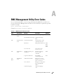
A BMC Management Utility Error Codes
B Using Console Redirection
Hardware Requirements .
Software Requirements
. . . . . . . . . . . . . . . . . . . . . . . . .
63
. . . . . . . . . . . . . . . . . . . . . . . . . .
63
Configuring the Host System
. . . . . . . . . . . . . . . . . . . . . . . .
Configuring the Client System
. . . . . . . . . . . . . . . . . . . . . . .
Configuring the Serial Port . . . .
Configuring the Terminal Settings
2
Contents
64
. . . . . . . . . . . . . . . . . . .
64
64
. . . . . . . . . . . . . . . . . . . .
65
. . . . . . . . . . . . . . . . . . . . .
65
Managing the Host System Remotely
Configuring Special Key Functions
63
. . . . . . . . . . . . . . . . . . .
C Terminal Mode Commands
Security Information.
. . . . . . . . . . . . . . . . . . . . . . . . .
Hex-ASCII Command Format
. . . . . . . . . . . . . . . . . . . . . . . .
70
. . . . . . . . . . . . . . . . . . . . . . . . . . .
71
. . . . . . . . . . . . . . . . . . . . . . . . . . . . . .
71
Text Command Format
Examples .
Terminal Mode IPMI Message Bridging
. . . . . . . . . . . . . . . . . .
72
. . . . . . . . . . . . . . . . . . . . . . .
77
. . . . . . . . . . . . . . . . . . . . . . . . . . . . . . . . . .
87
. . . . . . . . . . . . . . . . . . . . . . . . . . . . . . . . . . . .
99
Boot Option Parameters .
Glossary
Index
69
Figures
Figure 1-1.
BMC Configuration Matrix
Figure 2-1.
User Configuration Screen .
Figure 2-2.
Edit User Configuration Screen
Figure 2-3.
LAN Channel Configuration Screen
Figure 2-4.
Serial Over LAN Configuration Screen
Figure 3-1.
Installing on a Management Station
Figure 3-2.
IPMI Shell Diagram
Figure 3-3.
IPMI Help Option Example 1
. . . . . . . . . . . .
35
Figure 3-4.
IPMI Help Option Example 2
. . . . . . . . . . . .
36
Figure 3-5.
identify Option Example
. . . . . . . . . . . . . .
37
Figure 3-6.
sysinfo Option Example
. . . . . . . . . . . . . .
38
Figure 3-7.
power Option Example .
. . . . . . . . . . . . . .
39
Figure 3-8.
sel Option Example
. . . . . . . . . . . . . . . .
41
Figure 3-9.
SOL Proxy Diagram
. . . . . . . . . . . . . . . .
42
Figure 3-10.
SOL Proxy Main Menu Example
. . . . . . . . . . . . .
. . . . . . . . . . . .
. . . . . . . . . .
. . . . . . . .
7
17
18
20
. . . . . . .
24
. . . . . . . .
28
. . . . . . . . . . . . . . . .
31
. . . . . . . . . .
45
Contents
3
Figure 3-11.
Connecting to the Remote System’s BMC .
Figure 3-12.
Figure 3-13.
Figure 3-14.
. . . . .
47
Configuring the Serial-Over-LAN for the
Remote System, Example 1 . . . . . .
. . . . . .
48
Configuring the Serial-Over-LAN for the
Remote System, Example 2 . . . . . .
. . . . . .
49
Configuring the Serial-Over-LAN for the
Remote System, Example 3 . . . . . .
. . . . . .
50
. . . . . . . . . . .
51
. . . . . . . . . . . . . . . . .
52
Figure 3-15.
Console Redirection Example
Figure 3-16.
Reboot Example .
Figure 3-17.
Sample Help Screen .
Table 1-1.
BMC LAN Alerting Configuration Guidelines
. . . .
8
Table 1-2.
BMC LAN Access Configuration Guidelines .
. . . .
8
Table 1-3.
BMC Serial Configuration Guidelines
. . . . . . . .
9
Table 1-4.
BMC SOL Configuration Guidelines .
. . . . . . . .
9
Table 2-1.
Using Setup Screens
Table 2-2.
Setup Console Redirection Submenu Items
Table 3-1.
IPMI Shell Commands
Table A-1.
BMC Management Utility Error Codes
Table B-1.
. . . . . . . . . . . . . . .
53
Tables
4
Contents
. . . . . . . . . . . . . .
14
. . . .
14
. . . . . . . . . . . . . .
36
. . . . . .
57
Supported Escape Sequences
. . . . . . . . . .
63
Table B-2.
Additional Escape Sequences
. . . . . . . . . .
65
Table C-1.
Terminal Mode Request to BMC
Table C-2.
Terminal Mode Request from BMC .
Table C-3.
Supported BMC Combinations for IPMI
Message Bridging . . . . . . . . . .
Table C-4.
Terminal Mode Text Commands
Table C-5.
Boot Option Parameters
Table C-6.
Terminal Mode Configuration
. . . . . . . . .
. . . . . . .
. . . . . .
69
69
70
. . . . . . . . .
71
. . . . . . . . . . . . .
76
. . . . . . . . . .
84
1
Introduction
The Dell™ PowerEdge™ systems baseboard management controller (BMC) monitors the system
for critical events by communicating with various sensors on the system board and sends alerts and
log events when certain parameters exceed their preset thresholds. The BMC supports the
industry-standard Intelligent Platform Management Interface (IPMI) specification, enabling you
to configure, monitor, and recover systems remotely. The BMC provides the following features:
•
Allows access through the system’s serial port and integrated NIC
•
Fault logging and SNMP alerting
•
Access to system event log (SEL) and sensor status
•
Control of system functions including power on and off
•
Support that is independent of the system’s power or operating state
•
Text console redirection for system setup, text-based utilities, and operating system consoles
•
Access to the Microsoft EMS/SAC and Red Hat Linux serial console interfaces by using serial
over LAN (SOL).
Dell provides several distinct utilities and programs for accessing the BMC to perform
management activities. The following BMC interfaces allow users to configure and manage your
system through the BMC.
•
The BMC Management Utility allows remote, out-of-band LAN and/or serial port power
control, event log access, and console redirection.
•
The System Maintenance Utility (SMU) is an EFI-based configuration tool that provides the
ability to configure the BMC.
•
Dell OpenManage Server Administrator allows remote, in-band access to event logs, power
control, and sensor status information and provides the ability to configure the BMC.
•
In addition, the BMC can be accessed by standard, off-the-shelf terminal or terminal
emulator utilities that allow access to sensor status information, and power control.
Introduction
5
www.dell.com | support.dell.com
Supported System
The BMC-management features documented in this guide are supported on the following Dell
PowerEdge system:
•
7250
BMC Configuration and Management Tasks
This user’s guide documents the basic tasks needed to set up and configure the BMC on a
managed system in preparation for using the BMC Management Utility. These basic tasks can be
broken down into the two following sections:
•
Configuring a managed system’s BMC
•
Managing a remote managed system by accessing its BMC
Configuring the BMC
To configure the BMC in a pre-boot environment, you can use the System Maintenance Utility.
Alternately, you can configure the BMC on a managed system with a running operating system
using the Sever Administrator home page GUI or CLI.
Managing the BMC
To manage a remote managed system by accessing its BMC in a pre-boot environment, or by
accessing the BMC of a nonresponsive system, you must use the BMC Management Utility. To
configure the BMC on a system with a running operating system or to preform everyday BMC
management tasks, you can use the Server Administrator home page GUI.
Planning for Using Your System’s BMC
How you plan to use the BMC to manage your system dictates the configuration procedures you
will need to perform. The following are some likely configuration scenarios:
•
Configure BMC LAN alerting so that you can monitor your managed system using IT
Assistant.
•
Configure BMC LAN Access so that you can use the BMC Management Utility’s IPMI Shell
to access your system’s BMC over a shared LAN.
•
Configure BMC Serial Access so that you can use the BMC Management Utility’s IPMI Shell
or a text console redirection to access your system’s BMC over a serial cable.
•
Configure BMC Serial Over LAN Access so that you can use the BMC Management Utility’s
SOL Proxy to access your system’s BMC over a shared LAN to activate console redirection.
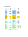
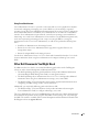
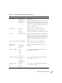
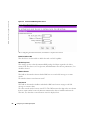
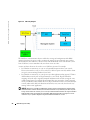
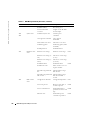
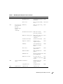
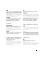
Consult the BMC Configuration Matrix (Figure 1-1), as well as the sections describing each likely
configuration scenario, before moving on to the next chapter "Configuring Your Managed System."
6
Introduction
Figure 1-1. BMC Configuration Matrix
Introduction
7
www.dell.com | support.dell.com
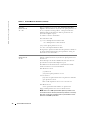
Basic BMC Alerting Over a Shared LAN
If you plan to only use your system’s BMC functionality to monitor BMC Alerts using IT Assistant,
you will need follow the BMC configuration guidelines listed in Table 1-1.
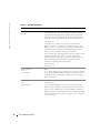
Table 1-1. BMC LAN Alerting Configuration Guidelines
Features
Connection
Medium
BMC Configuration Tools
Basic Configuration Tasks
BMC Management
Tools
SNMP Traps
Accessed over a
Shared LAN
• SMU (pre-operating system • Enable alerting on the
IT Assistant
environment)
managed system
• Server Administrator
• Configure IP address on
managed system
• Configure Subnet mask on
managed system
• Configure Gateway on
managed system
• Configure Alert destination
IP address
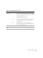
IPMI Shell Over a Shared LAN
If you plan to use the BMC Management Utility’s IPMI Shell to access your system’s BMC over a
shared LAN, you will need follow the BMC configuration guidelines listed in Table 1-2.
Table 1-2. BMC LAN Access Configuration Guidelines
Features
Connection
Medium
BMC Configuration Tools
Basic Configuration Tasks
BMC Management
Tools
• Remote SEL
Access
• Power control
• ID
• System
Information
Accessed over a
shared LAN
• SMU (pre-operating system • Configure BMC user(s)
IPMI Shell
environment)
• Enable LAN on managed
• Server Administrator
system
• Configure IP address on
managed system
• Configure Subnet mask on
managed system
• Configure Gateway on
managed system
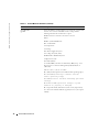
IPMI Shell Over the Serial Cable
If you plan to use the BMC Management Utility’s IPMI Shell or a text console redirection to access
your system’s BMC over a serial cable, you will need follow the BMC configuration guidelines listed
in Table 1-3.
8
Introduction
Table 1-3. BMC Serial Configuration Guidelines
Features
Connection
Medium
•
•
•
•
Accessed through • SMU (pre-operating system • Configure BMC user(s)
• IPMI Shell
the serial channel
environment)
(Basic Mode
• Enable BMC Serial in BIOS
by using a null
only)
• Server Administrator (to
• Set BMC serial to either
modem cable
enable BMC serial only)
•
Terminal
Basic mode or Terminal
emulation
mode
(Terminal
• Set Baud rate (9600 or
Mode only)
19200)
SEL Access
Power control
ID
System
Information
BMC Configuration Tools
Basic Configuration Tasks
BMC Management
Tools
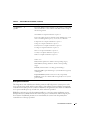
SOL Proxy Over a Shared LAN
If you plan to use the BMC Management Utility’s SOL Proxy to access your system’s BMC over a
shared LAN, you will need follow the BMC configuration guidelines listed in Table 1-4.
Table 1-4. BMC SOL Configuration Guidelines
Features
Connection
Medium
• Text Utility
Accessed over a
Console
shared LAN
redirection
• Remote BIOS
setup
• Microsoft text
console
redirection
• Red Hat Linux
text console
redirection
BMC Configuration Tools
Basic Configuration Tasks
• SMU (pre-operating system • Configure BMC user(s)
environment)
• Enable BMC NIC in BIOS
• Server Administrator (to
• Configure BIOS text
enable BMC serial only)
console redirection
– Enable
– Set Baud rate (9600 or
19200)
– Set terminal emulation
type (VT100 or ANSI)
BMC Management
Tools
• SOL Proxy
• Microsoft text
console
redirection
• Red Hat Linux
text console
redirection
Introduction
9
www.dell.com | support.dell.com
BMC Configuration and Management Tools
Using the System Maintenance Utility
The System Maintenance Utility is an EFI-based program that provides the ability to view or
modify the systems management firmware configuration, which is maintained by the BMC.
The SMU lets you:
•
Configure the serial channel for remote systems management over a direct serial connection.
•
Configure the LAN channel for remote systems management over the network.
•
Configure users and associated passwords for channel access. Users and channels can be
assigned privilege levels to further define the access levels.
•
Configure platform events to define the actions that should take place when specific events
occur.
•
Configure serial over LAN and terminal mode capabilities.
•
Configure the power restore policy for the system.
•
View, save, and clear the BMC System Event Log.
•
View and save the BMC Sensor Data Records.
•
View and save the Field Replaceable Unit records.
Using the BMC Management Utility
The BMC Management Utility provides a command-line, remote management station to manage
all supported BMC functions. Use the BMC Management Utility to manage your system from a
remote management station and as your managed system’s emergency management console. The
utility gives you the option of using either a command line interface (IPMI Shell) or a serial over
LAN proxy (SOL Proxy) to access and manage the BMC. To use the BMC Management Utility,
you will need to perform the following basic tasks:
NOTE: You must first configure your BMC using the SMU or Server Administrator before you can use the
BMC Management Utility.
•
Configure BIOS setting to allow console redirection
•
Configure the BMC using the SMU or Server Administrator.
•
Install the BMC Management Utility to a management station
See "Configuring Your Managed System" for instructions on configuring your managed system in
preparation for using the BMC Management Utility, and see "BMC Management Utility" for
complete instructions on using the BMC Management Utility to manage your system BMC.
10
Introduction
Using Sever Administrator
Server Administrator Version 1.8.3 provides a convenient and easy-to-use graphical user interface
for remotely configuring or managing your system’s BMC on a system running a supported
operating system. The Server Administrator Instrumentation Service can be used to configure the
most relevant BMC features. In addition, Server Administrator can be utilized as command line
interface. Server Administrator requires that the system has an operating system installed and
functioning. As a result, Server Administrator is best suited for everyday BMC management tasks,
and is not an option for performing pre-boot setup or accessing the BMC as a emergency
management console. To use Server Administrator, you will need to perform the following basic
tasks:
•
Install Server Administrator on the managed system.
•
Remotely access the Server Administrator home page from a supported browser on a
management station.
•
Remotely configure BMC on the managed system.
See the Server Administrator Version 1.8.3 User’s Guide and Command line Interface User’s Guide
for more information about using Server Administrator to configure and manage your system
BMC.
Other Dell Documents You Might Need
In addition to this User's Guide, you can find the following guides either on the Dell Support
website or on the Systems Management and Documentation CD:
•
The Dell OpenManage Software Quick Installation Guide provides additional information
about installing the BMC Management Utility on a management station.
•
The Dell OpenManage Server Administrator Version 1.8.3 User’s Guide provides additional
information about using Server Administrator to manage your system’s BMC.
•
The Dell PowerEdge 7250 Systems Product Guide provides supplemental information about
configuring your BIOS settings to allow console redirection.
Additionally, you can find the following guide on the Resource CD:
•
The Dell PowerEdge 7250 System Software Guide provides information about using the
System Maintenance Utility to configure and manage your system.
The Server Administrator version 1.8.3 readme.txt file provides the latest available information for
the installation and operation of the programs and utilities used to manage your system through
the BMC. The readme is available on the Systems Management and Documentation CD and on the
Dell Support website at support.dell.com.
Introduction
11
www.dell.com | support.dell.com
Obtaining Technical Assistance
If at any time you do not understand a procedure described in this guide or if your product does not
perform as expected, help tools are available to assist you. For more information about these help
tools, see "Getting Help" in your system's Installation and Troubleshooting Guide.
Additionally, Dell Enterprise Training and Certification is available; see www.dell.com/training for
more information. This service may not be offered in all locations.
12
Introduction
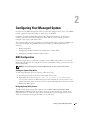
2
Configuring Your Managed System
In order to use the BMC Management Utility, you must first configure the necessary system BIOS,
network, and serial connection settings to enable access to the BMC.
In addition, to utilize the BMC Management Utility IPMI Serial functions, you must have a
working connection between the management station and the correct serial I/O port of the
managed system, using a null modem cable.
This section describes the basic procedures you must perform in order to prepare your BMC to be
accessed and managed using the BMC Management Utility. The following procedures are
described:
•
BIOS Configuration
•
Configuring Your BMC with the System Maintenance Utility (SMU)
•
Configuring Your BMC with Server Administrator
BIOS Configuration
For most configurations you will need to configure specific BIOS settings before you can use the
BMC Management Utility. To configure the necessary system BIOS settings, your must enter the
System Setup utility.
NOTE: For more information about configuring BIOS settings, see your system’s Product Guide.
Starting the System Setup Utility
To start Setup during the power-on sequence, follow these steps:
1
Press the power button on the front control panel of the system.
2
When POST shows the message Hit <F2> if you want to run SETUP, press
<F2>. If the system has an administrator password configured, the system prompts you to
enter the password. If the system does not have a password configured, the main screen of the
BIOS Setup utility appears.
Navigating Setup Utility Screens
The BIOS Setup utility consists of five primary menus: Main, Advanced, Security, System
Management, and Exit. Each menu occupies a single screen and presents a list of menu items.
Some menu items are submenus, while others are settings that you can change from the screen.
Table 2-1 describes how to navigate the utility screens and menus.
Configuring Your Managed System
13
www.dell.com | support.dell.com
Table 2-1. Using Setup Screens
Key
Action
Left arrow Scroll left through the main menu screens
Right
arrow
Scroll right through the main menu screens
Enter
Select a submenu item or accept a drop-down choice
Tab
Select a field within a value (for example, date field)
F9
Select the default value
F10
Save your changes and exit Setup
ESC
Go back to a previous screen
Up arrow
Scroll up through menu items or value lists
Down
arrow
Scroll down through menu items or value lists
Using the System Setup Utility
1
Navigate to the Systems Management menu.
2
Navigate to the Console Redirection menu item and press <Enter>.
3
Configure all Setup Console Redirection submenu items necessary for the method you have
chosen to access your managed system’s BMC. See Table 2-2 for a list of all valid Setup
Console Redirection submenu items. Default values, if applicable, are enclosed in brackets.
See Figure 1-1 for an overview of the necessary setup procedures.
4
Navigate to the Exit menu and select Exit Saving Changes. When prompted, select Yes to
save your changes and exit the utility.
Table 2-2. Setup Console Redirection Submenu Items
Submenu Item
Default Value
Description
Serial Console
Redirection
Enabled
When enabled, Console Redirection uses only COM2.
Choosing Disabled completely disables Console
Redirection.
Baud Rate
9600
[19.2K]
Disabled
38.4K
57.6K
115.2K
14
Configuring Your Managed System
When Console Redirection is enabled, use the baud rate
specified. When the BMC Management Utility is
sharing the COM port as console redirection, the baud
rate must be set to 19.2K to match the utility’s baud
rate.
Table 2-2. Setup Console Redirection Submenu Items (continued)
Submenu Item
Default Value
Description
Flow Control
No Flow Control
[CTS/RTS]
CTS/RTS + CD
No flow control.
CTS/RTS = Hardware-based flow control.
CTS/RTS +CD = Hardware-based + carrier-detect flow
control. When the BMC Management Utility is sharing
the COM port as console redirection, the flow control
must be set to CTS/RTS or CTS/RTS+CD depending
on whether a modem is used.
XON/XOFF
Xon/Xoff = Software-based flow control.
Terminal Type
[PC-ANSI]
VT100+
VT-UTF8
Serial Port
COM2 2F8 IRQ3
Remote Console Reset Enabled/Disabled
Select terminal type. VT100+ only available when
English selected as the language. VT-UTF8 uses
UNICODE. PC-ANSI is the standard PC-type terminal.
Hardcoded – no selection available. Note that if Console
Redirection is enabled, then the Base I/O address and
IRQ selection of Serial Port B (under Menu Advanced,
submenu Peripheral Configuration) should match this
Serial Port setting under the Console Redirection
submenu.
Enables remote reset using escape key sequence;
<ESC> <R> <ESC> <r> <ESC> <R>
ACPI OS Headless
Operation
Disabled
ACPI OS Baud Rate
9600
Same as BIOS
Used to pass information about serial redirection to
ACPI OS.
Serial Port
19.2k
Only available when ACPI OS Headless Operation is
same as BIOS or Serial Port.
38.4K
57.6k
115.2k
ACPI OS Flow Control No Flow Control
CTS/RTS
Only available when ACPI OS Headless Operation is
same as BIOS or Serial Port.
XON / XOFF
CTS/RTS + CD
ACPI OS Terminal
Type
PC-ANSI
VT100+
Only available when ACPI OS Headless Operation is
same as BIOS or Serial Port.
VT-UTF8
Configuring Your Managed System
15
www.dell.com | support.dell.com
Configuring Your Managed System with the System
Maintenance Utility (SMU)
NOTE: The SMU can be run from both the Resource CD and from the system’s utility partition (UT). See
the System Software Guide on the Resource CD for instructions on running the SMU from the UT.
The managed system must have a CD drive. A network connection is not required.
The following sequence of steps is followed to start the SMU locally (using the system Resource
CD):
1
Insert the system Resource CD into the CD drive on the managed system and boot the
system to the EFI shell. The Resource CD menu program begins running automatically and
displays a splash screen followed by the main menu.
2
Use the arrow keys to move to the Utilities menu item. Press the <Enter> key.
3
Use the down arrow key to highlight the System Maintenance Utility menu item. Press the
<Enter> key to start the local SMU application.
The server management configuration task appears in the task pane of the SMU. This task allows
you to configure server management settings maintained by the BMC. The server management
configuration task supports configuring of the following, which are displayed as sub-tasks:
•
Users
•
LAN Channel
•
Serial/Modem
•
Platform Event Filtering (PEF)
•
Power Settings
Upon selecting one of the above sub-tasks, a screen is displayed that contains some or all of the
configuration items that pertain to the selected sub-task. The data that is initially displayed is read
from the server management controller of the system. You can update the settings and save them
back to the system.
Sub-tasks can be made up of one or more screens, depending on the server management
configuration settings you enabled. Buttons that are common to the server management
configuration tasks are:
Save — Causes the current values of the settings in the current subtask to be stored in non-volatile
memory on the system.
Edit — Causes a screen to be displayed that allows you to change settings related to a single entry
in a table.
16
Configuring Your Managed System
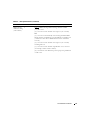
User Configuration Subtask
The User Configuration subtask provides a way to configure the user access to the LAN and Serial
channels. Up to four users are allowed. Some of the options presented in these screens depend on
how the channels have been configured; therefore, the channels should be configured before you
access these settings.
Sessions allow a framework for user authentication and allow multiple IPMI messaging streams on
a single channel.
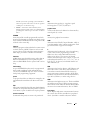
After clicking on the User Configuration subtask, the screen displayed below is shown. This screen
displays an entry for each possible user that can be configured. This screen shows:
•
Whether a particular user is enabled or disabled for channel access
•
Whether a password is set for the user
•
The BMC privilege level the user has for each of the available channels that supports sessions
(users can only access channels that support sessions)
Figure 2-1. User Configuration Screen
The first user is always present and is used to support an anonymous login. The username for this
user is null (blank) and cannot be changed; the user name displays the text Anonymous User. The
password can be set to a desired value.
It is possible for multiple user entries to have the same username. This occurs if a different
password is needed for the same user on different channels. In this case, the privilege level for the
channel that is not to be accessed with the associated password should be set to No Access.
Configuring Your Managed System
17
www.dell.com | support.dell.com
Otherwise, the firmware attempts to use the first entry in the user table that it finds that allows
access to the specified channel and would expect the password associated with that entry to be the
one entered to gain access to the specified channel.
The figure below shows the screen that is displayed when a User Name is selected and then the
Edit button is clicked. Changes made to user settings do not take effect until the next time that
the user establishes a session.
After configuring the user information, click Save to complete this sub-task.
Figure 2-2. Edit User Configuration Screen
After editing the user information, click OK to return to the User Configuration screen.
Enable User
This check box is used to enable you to attempt to have access to the available channels. Leaving
the box unchecked disables the user, preventing that user from accessing the channels.
Enter Username
This edit box is used to enter an out-of-band username. If the anonymous user is selected for
modification, the screen displayed does not include this edit box because the user name cannot be
changed.
18
Configuring Your Managed System
The password can be from 1 to 16 ASCII characters long. The characters accepted by the SMU for
usernames are the ASCII printable characters in the range 0x21 through 0x7e, except for left and
right bracket characters ('[' and ']'). These characters are reserved for framing packets for terminal
mode sessions.
Clear Password
This check box is used to clear the password for the user. If this box is checked, the Enter and Verify
New Password edit boxes are disabled.
Enter/Verify New Password
These edit boxes allow you to enter the password for the user. The Verify New Password edit box
ensures that the password entered in the Enter New Password edit box is correct. As a user enters a
password, asterisks are displayed. If a password already exists, these fields show ******** when you
enter this screen.
This password can be between 1 and 16 ASCII characters in length. The characters accepted by the
SMU for user passwords are the ASCII printable characters in the range 0x21 through 0x7e, except
for left and right bracket characters ([ and ]), since those characters are used for framing packets for
terminal mode sessions.
NOTE: If the Clear Password check box is checked, these two edit boxes are disabled.
If a user password is currently set, the SMU user is not required to enter the current password
before changing it.
User Privilege Level for LAN Channels
This combo box allows you to select the privilege level for LAN channel. The global privilege level
set for LAN channel access takes precedence over the user privilege level. For example, if the LAN
channel is configured for user access only, then users are limited to user operations regardless of the
user privilege level.
User Privilege Level for Serial Channel
This combo box allows you to select the privilege level for serial channel access. The privilege level
set for the serial channel takes precedence over the user privilege level. For example, if the serial
channel is configured for user access only, then users are limited to user operations regardless of the
user privilege level.
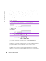
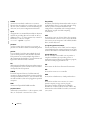
LAN Channel Configuration Subtask
The LAN channel configuration subtask allows you to modify settings related to the LAN channel.
The initial screen for configuring the LAN channel and the configuration settings are described in
Figure 2-3.
Configuring Your Managed System
19
www.dell.com | support.dell.com
Figure 2-3. LAN Channel Configuration Screen
After completing this screen, click Next to move to the next screen to continue this sub-task.
Default LAN Configuration Settings Set by the SMU
The SMU automatically configures some server management firmware settings. These are not
displayed on the screen above, but are listed below. Before these settings are set by the SMU, you
must click through each LAN configuration screen by clicking the Next button until you reach the
Save button on the final LAN configuration screen.
20
•
Gratuitous ARPs may be enabled: This setting allows the BMC to generate gratuitous ARPs,
which provide a mechanism for IP devices to locate the hardware addresses of other devices
on the local network. If the system has a valid IP address and the LAN channel is enabled for
messaging (the access mode is not set to Disabled) or alerting, then gratuitous ARPs are
enabled.
•
Authentication enables are enabled: These bits define what types of authentication are
enabled to authenticate messages sent to the BMC by users of different privilege levels. The
SMU enables authentication of type straight password, MD2, MD5, and none.
•
User-level authentication is disabled: The SMU disables user-level authentication so that if a
user is attached with a privilege level of User, no authentication is done on messages sent to or
from the BMC. This improves the session performance.
Configuring Your Managed System
Access Mode
This drop-down box configures the access mode for the LAN channel. The available options are:
•
Always Available: The channel is dedicated to communication with the BMC and is available
during all system states (powered-down, powered-up, pre-boot, sleep, run-time, etc.).
•
Disabled: The channel is not allowed to communicate with the BMC.
BMC Privilege Level Limit
This drop-down box determines the maximum privilege level at which communication on the
channel can take place. It is a global privilege level that takes precedence over user privilege levels.
For example, if a channel privilege level is set to the user level then only user-level commands can
be executed, regardless of the user privilege level.
The meanings of the different privilege levels are described below:
•
Callback: Only commands needed to initiate a callback session are allowed. Although Dell
OpenManage system management software does not support callback as a connection
mechanism, it is still a valid privilege level because it defines a set of BMC commands that
can be executed by a user.
•
User: Only "benign" commands are allowed. These are primarily commands that read data
structures and retrieve status. Commands that can be used to alter BMC configuration, write
data to the BMC or other management controllers, or perform system actions such as resets,
power on/off, and watchdog activation are disallowed.
•
Operator: All BMC commands are allowed, except for configuration commands that can
change the behavior of the out-of-band interfaces. For example, Operator privilege does not
allow the capability to disable individual channels, or to change user access privileges.
•
Administrator: All BMC commands are allowed, including configuration commands. An
administrator can execute configuration commands that would disable the channel that the
Administrator is communicating over.
Enable DHCP
The Enable Dynamic Host Configuration Protocol (DHCP) check box enables or disables the
dynamic host configuration protocol to allow the system to automatically assign the Host IP
address, Default Gateway address, and Subnet mask. The IP address is assigned by the DHCP
server as a part of the system boot process. If an IP Address lease expires after the system boots, the
BMC will continue to use the expired address. It is recommended that IP addresses be assigned
with permanent leases.
When this option is enabled, the Host IP address, Subnet Mask, and Default Gateway IP Address
fields are disabled.
Configuring Your Managed System
21
www.dell.com | support.dell.com
Host IP Address
This edit box is for the logical or Internet address of the host. The IP address is required when
DHCP is disabled. The IP address is entered as a dotted notation, such as 192.168.0.2.
Subnet Mask
The edit box is for the host's subnet mask. The system uses this to decide if alert destinations are in
the local subnet or in another subnet relative to the client console. The Subnet Mask is entered as a
dotted notation, such as 255.255.0.0.
Default Gateway IP Address
This edit box is for the IP address of the router used when the BMC sends a message or an alert to
a system on a different subnet than the BMC is on. The IP address is entered as a dotted notation,
such as 192.168.0.2.
Default Gateway MAC Address
This edit box allows you to enter the MAC address of the default gateway router. The MAC address
is entered as a series of six pairs of hex digits separated by dashes, such as 00-01-62-d0-3e-66.
Alphabetic hex digits (a-f) can be entered in uppercase or lowercase. This edit box is disabled by
default and is only activated if the check box for Automatically resolve Default Gateway MAC
address is not checked. If the edit box is cleared (no address is supplied), a message is displayed
asking that a valid address be entered.
Automatically Resolve Default Gateway MAC Address
This check box allows you to specify whether the BMC should automatically attempt to resolve the
MAC address of the default gateway router. This box is checked by default unless the MAC address
edit box appears to include a valid MAC address.
If this box is not checked, you must provide the MAC address in the Default Gateway MAC
Address field.
When the Next button is clicked, the firmware attempts to resolve the gateway MAC address. If
the BMC cannot resolve the address, the screen is redisplayed with the box unchecked and you are
asked to provide the MAC address in the Default Gateway MAC Address field. If the screen is
redisplayed due to a MAC address resolution issue, any user data previously entered, other than the
MAC address information, remains in place.
Backup Gateway IP Address
This edit box allows you to enter the IP address of a backup gateway router. The IP address is
entered as a dotted notation, such as 192.168.0.2.
22
Configuring Your Managed System
Backup Gateway MAC Address
This edit box allows you to enter the MAC address of the backup gateway router. The MAC address
is entered as a series of six pairs of hex digits separated by dashes, such as 00-01-62-d0-3e-66.
Alphabetic hex digits (a-f) can be entered in uppercase or lowercase. This edit box is disabled by
default and is only activated if the check box for Automatically resolve Backup Gateway MAC
address is not checked.
Automatically Resolve Backup Gateway MAC Address
This check box allows you to specify whether the BMC should automatically attempt to resolve the
MAC address of the backup gateway router. This box is checked by default unless the MAC address
edit box appears to include a valid MAC address.
If this box is not checked, you must provide the MAC address in the Backup Gateway MAC
Address field.
When the Next button is clicked, the firmware attempts to resolve the gateway MAC address. If
the BMC cannot resolve the address, the screen is redisplayed with the box unchecked and you are
asked to provide the MAC address in the Backup Gateway MAC Address field. If the screen is
redisplayed due to a MAC address resolution issue, any user data previously entered, other than the
MAC address information, remains in place.
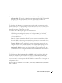
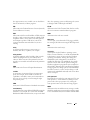
Serial Over LAN Configuration Subtask
The Serial Over LAN screen, shown in Figure 2-4, allows you to configure the operation of the
serial over LAN capability of the BMC.
The SMU sets up the SOL configuration such that SOL packets do not have to be authenticated.
This enhances the performance of an SOL session.
Configuring Your Managed System
23
www.dell.com | support.dell.com
Figure 2-4. Serial Over LAN Configuration Screen
After configuring the SOL information, click Save to complete this subtask.
Enable Serial Over LAN
This check box is used to enable or disable the serial over LAN capability.
SOL Privilege Level
This setting is used to select the minimum BMC privilege level that is required to be able to
activate SOL. The choices are User, Operator, and Administrator. For the best performance, User
should be selected.
Number of Retries
This field sets the number of times that the BMC tries to resend a SOL message to a remote
console.
The number of retries must between 0 and 7.
Retry Interval
This field sets the number of milliseconds that the BMC waits between trying to send SOL
messages to a remote client.
The value entered must be between 0 and 2559. The SMU truncates the digit in the ones column
from any input number because the firmware maintains this value in 10 millisecond intervals.
Therefore, any value that is entered between 0 and 9 is displayed as 0.
24
Configuring Your Managed System
Baud Rate
This field sets the baud rate at which serial data is transferred by the BMC when SOL is active. The
choices are Default IPMI, 9600 bps, 19.2 kbps, 38.4 kbps, 57.6 kbps, and 115.2 kbps. If Default
IPMI is selected, the baud rate used is the rate currently set for BIOS serial redirection. When SOL
is active, serial communication with the BMC always occurs with 8 data bits, no parity, 1 stop bit,
and RTS/CTS (hardware) flow control.
LAN Alert Configuration
See the System Software Guide on the Resource CD for information about configuring BMC LAN
alerts. Click Next to move to the Serial Over LAN screen.
Configuring Your Managed System with Server Administrator
You can also configure the BMC options using Server Administrator Version 1.8.3. Server
Administrator is a one-to-one system management software program that must be installed on the
managed system. Once installed, Server Administrator can be remotely accessed from a
management station with a supported browser to perform BMC configuration tasks. See the Sever
Administrator User’s Guide for more information about installing and using the Server
Administrator.
You can configure the BMC settings from either the Server Administrator home page or from its
command line interface. Users must have Administrator privileges to access the BMC settings.
Users logged in with User or Power User group privileges can view the BMC information but
cannot change the settings.
See the Server Administrator Version 1.8.3 Command Line Interface User's Guide for information
about configuring the BMC from the command line.
When using Server Administrator, you can click Help on the global navigation bar for more
detailed information about the specific window you are viewing. Server Administrator help is
available for all windows accessible to the user based on user privilege level and the specific
hardware and software groups that Server Administrator discovers on the managed system.
Configuring Your Managed System to Access its BMC
The Server Administrator Instrumentation Service allows you to manage Baseboard Management
Controller (BMC) features such as general BMC information, configuration of the LAN and serial
port, and BMC users. To use Server Administrator to configure the BMC on a managed system,
perform the following steps:
NOTE: You must be logged in with Admin privileges to configure the BMC settings.
1
Log in to the Server Administrator home page for the target system.
2
Click the System object.
3
Click the Main System Chassis object.
Configuring Your Managed System
25
www.dell.com | support.dell.com
4
Click the BMC object.
5
The BMC Information window appears.
6
Click the Configuration tab.
Under the Configuration tab, you can configure LAN, Serial Port, and Serial Over LAN.
7
Click the Users tab.
Under the Users tab, you can modify the BMC user configuration.
26
Configuring Your Managed System
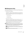
3
BMC Management Utility
The BMC Management Utility is comprised of a collection of software applications that enable
remote management and configuration of systems equipped with a BMC. The BMC Management
Utility includes the following components:
•
Command Line Interface (IPMI Shell)
The IPMI Shell is a scriptable console application program for the control and management
of remote systems using the IPMI 1.5 protocol. The IPMI Shell supports both serial access
and LAN access to the BMC. It allows administration of one or more managed systems from a
command line shell, rather than a graphical user interface (GUI). The IPMI Shell is used to
perform the following tasks:
•
–
System power management
–
System identification
–
Access to the event log
–
System identifier control
Serial Over LAN Proxy (SOL Proxy)
The SOL Proxy is a telnet daemon that allows LAN-based administration of remote systems
using the Serial Over LAN (SOL) and IPMI 1.5 protocols. Any standard telnet client
application, such as HyperTerminal on Microsoft® Windows® or telnet on Red Hat® Linux,
can be used to access the daemon's features. The SOL protocol coupled with the remote
system's BIOS console redirection allows administrators to remotely view and change a
managed system’s BIOS settings over a LAN. The Red Hat Linux serial console and
Microsoft's EMS/SAC interfaces can also be accessed over a LAN using SOL.
NOTICE: All versions of the Microsoft Windows operating system include Hilgraeve's HyperTerminal
terminal emulation software. However, the included version does not provide many functions required
during console redirection. Instead, you can use any terminal emulation software that supports VT100 or
ANSI emulation mode. One example of a full VT100 or ANSI terminal emulator that supports console
redirection on your system is Hilgraeve's HyperTerminal Private Edition 6.1 or later.
NOTE: See "Using Console Redirection" for more information about console redirection, including
hardware and software requirements and instructions for configuring host and client systems to use
console redirection.
NOTE: HyperTerminal and telnet settings must be consistent with the settings on the managed
system. For example, the baud rates and terminal modes should match.
BMC Management Utility
27
www.dell.com | support.dell.com
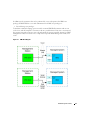
Installing the BMC Management Utility
The BMC Management Utility is installed on a management station system in order to remotely
connect to the managed system’s BMC. See Figure 3-1.
Installation Prerequisites
Before using the BMC Management Utility, you must perform at least the basic BIOS and BMC
configuration tasks described in "Configuring Your Managed System."
In addition, to access the BMC using the IPMI serial feature, you must have a working connection
between the management station and the correct serial I/O port of the managed system’s BMC
using a null modem cable.
Figure 3-1. Installing on a Management Station
Supported Operating Systems
The management station must be running one of the following supported operating systems:
28
•
Red Hat Enterprise Linux 2.1 AS
•
Red Hat Enterprise Linux 3 AS, ES, WS
•
Microsoft Windows 2000
•
Microsoft Windows XP
•
Microsoft Windows Server 2003 Web, Standard, and Enterprise Editions
BMC Management Utility
Installation
To install the BMC Management Utility on the management station, perform the following steps:
1
Log on with administrator privileges to the system where you want to install the system
management software components.
2
Exit any open application programs and disable any virus-scanning software.
3
Insert the Systems Management and Documentation CD into your system's CD drive.
The setup program should start automatically. If it does not, click the Start button, click Run,
and then type x:autorun.exe (where x is the drive letter of your CD drive).
4
Click Install BMC Management Utilities.
5
Click OK.
6
Click Open to proceed through the installation process and respond to the prompts, as
required.
The setup program automatically installs all of the management station software for your
hardware configuration.
7
When the installation is complete, close the installation window.
See the for more information.
See the Dell OpenManage™ Version 1.8.3 User's Guide for additional information about installing
the BMC Management Utility on a management station.
Windows Operating Systems
By default, the installation program copies the files to the following directory:
C:\ProgramFiles\ Dell\OpenManage\bmcconsole.
Uninstalling the BMC Management Utility
To uninstall the BMC Management Utility, use the Add/Remove Programs utility in the Control
Panel.
Red Hat Linux Operating Systems
By default, the installation program copies the files to the following locations:
/etc/init.d/solproxy
/etc/solproxy.cfg
/usr/sbin/solproxyd
/usr/bin/solconfig
/usr/bin/ipmish
BMC Management Utility
29
www.dell.com | support.dell.com
The SOL Proxy will start automatically during system startup. Alternatively, you can go to directory
/etc/init.d and use the following command to manage the SOL Proxy service:
solproxy status
solproxy start
solproxy stop
solproxy restart
Uninstalling the BMC Management Utility
To uninstall the BMC Management Utility, perform the following procedures:
1
Log in as root.
2
Enter the following command to remove all the installed packages.
rpm -e osabmcutil
3
If you receive a success message, it shows that the BMC Management Utility is uninstalled.
IPMI Shell
IPMI Shell is a CLI console application and has no graphical user interface. Its commands and
options are specified using command line arguments only.
IPMI Shell supports out-of-band (OOB) access (over a LAN or through the serial port) to a single
system at a time, however, multiple IPMI Shell sessions can run simultaneously on the same
managed system. SeeFigure 3-2.
IPMI Shell allows a user with user-level BMC user privileges to:
•
Display the current power status
•
Display the 16-byte system GUID of the managed system
•
Display all field replaceable units (FRU) present in the system
•
Display the BMC firmware information
•
Display summary information about the event log
•
Display the logged events
In addition to the operations that can be performed by a user with user-level BMC user privileges,
IPMI Shell allows a user with operator-level BMC user privileges to:
30
•
Power on, reset, or cycle a managed system
•
Simulate a hard power off a managed system (forcing the system to turn off without shutting
down the operating system)
•
Delete the system event log (SEL)
•
Turn on/off the blinking system identification LED
BMC Management Utility
In addition to the operations that can be performed by a user with operator-level BMC user
privileges, IPMI Shell allows a user with administrator-level BMC user privileges to:
•
Set and change user privileges.
To facilitate command scripting, upon successful execution IPMI Shell terminates with an exit
code of zero, and will output the execution results in a parsable format. If an error is encountered,
the program exits with a non-zero error code and output the error in a parsable format. See "BMC
Management Utility Error Codes" for a complete list of possible BMC Management Utility error
codes.
Figure 3-2. IPMI Shell Diagram
BMC Management Utility
31
www.dell.com | support.dell.com
Using IPMI Shell
To use IPMI Shell, perform the following steps:
On systems running a supported Microsoft Windows operating system:
1
Start a Command Prompt window.
2
Go to the directory where the file ipmish.exe is located. By default, ipmish.exe is located at
the directory: C:\ProgramFiles\ Dell\OpenManage\bmcconsole.
3
Enter IPMI Shell commands (see "IPMI Shell Command Syntax") to manage the remote
system. Go to "IPMI Shell Commands" for a complete list of valid options, commands,
subcommands, and arguments.
On systems running a supported Red Hat Linux operating system:
1
Start an operating system (OS) shell.
2
Enter IPMI Shell commands (see "IPMI Shell Command Syntax") to manage the remote
system. Go to "IPMI Shell Commands" for a complete list of valid options, commands,
subcommands, and arguments.
IPMI Shell Command Syntax
The general syntax of IPMI Shell CLI commands is as follows:
ipmish [global-option] … command [; command] …
where a command is :
command [subcommand] [command option and argument] …
Both global options and command-specific options are always in the form of:
-option argument
For example:
-help
-max 20
-u John
Arguments with embedded tabs or spaces must be enclosed in matching double quotation marks
("). For example:
-user "John Smith"
Every command has one default action. The default action is typically, but not always, the
equivalent of reading and displaying the current setting or status for the command.
32
BMC Management Utility
IPMI Shell Global Options
IPMI Shell has the following global options:
IPMI Session Option -ip
Synopsis
ipmish -ip bmc_ip_address | bmc_hostname -u username -p password
Description
This option is used to establish a connection to a remote managed system using the LAN channel.
The IP port specified in installation (default value is 623) is used unless another port has been
configured.
Options
NOTE: The following options cannot be used independently. One or more IPMISH command must follow
the option.
-ip bmc_ip_address | bmc_hostname
Specifies the IP address or hostname of the remote managed system.
-u username
Specifies the BMC username used to connect to the system.
-p password
Specifies the BMC user password used to connect to the system.
IPMI Session Option -com
Synopsis
ipmish -com serial_port -baud baud_rate -flow flow_control
-u username -p password
Description
This option is used to establish a connection to a remote managed system using the serial channel.
BMC Management Utility
33
www.dell.com | support.dell.com
Options
NOTE: The following options cannot be used independently. One or more IPMISH command must follow
the option.
-com serial_port
Specifies the serial port used when establishing an IPMI session to the managed system. For a system
running Windows, the management station port can be 1, 2, 3, and so on. For systems running Red
Hat Linux, the management station port can be ttyS0, ttyS1, ttyS2, and so on.
-baud baud_rate
Specifies the communication baud rate over the serial channel, such as 9600 or 19200. The baud
rate for the serial channel should match the baud rate set in the managed system.
-flow flow_control
Specifies the data flow control method. There are two flow control options: CTS (hardware flow
control) and NONE (no flow control).
-u username
Specifies the BMC username used to connect to the managed system.
-p password
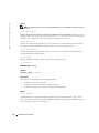
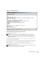
IPMI Help Option -help
Synopsis
ipmish -help [command]
Description
This option is used to display the following information:
•
A summary page for all commands
•
A summary of all subcommands for a single command
•
A detailed description of a command-subcommand combination
Options
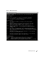
-help command
A command list and a capsule description of options are printed if no argument is given. When
there is an argument specifying a valid command, the help option displays a detailed description of
the command. See Figure 3-3 and Figure 3-4.
34
BMC Management Utility
Figure 3-3. IPMI Help Option Example 1
BMC Management Utility
35
www.dell.com | support.dell.com
Figure 3-4. IPMI Help Option Example 2
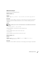
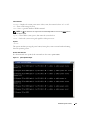
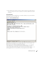
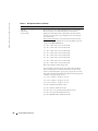
IPMI Shell Commands
The table below lists IPMI Shell commands with a brief description.
Table 3-1. IPMI Shell Commands
Command
Description
identify
Controls the identification LED on the front panel.
sysinfo
Retrieves and displays managed system information.
power
Controls the power state of the managed system.
sel
Displays or deletes information from the SEL.
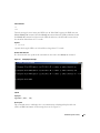
identify
Synopsis
identify [on [-t seconds] | off]
Description
This command is used to control the identification LED on the front panel. See Figure 3-5.
36
BMC Management Utility
Subcommands
on
off
Turns the managed system’s front panel LED on or off. If the BMC supports the IPMI extension
Chassis Identify On command, then the identify on command turns the LED on indefinitely until
the identify off command is used to turn the LED off. Otherwise, the LED will be turned on for
the maximum allowed time of 255 seconds.
Options
-t seconds
Specifies how long the LED is on. It should be no longer than 255 seconds.
Default Subcommand
If a subcommand is not specified, this command acts the same as the identify on command.
Figure 3-5. identify Option Example
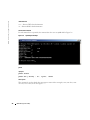
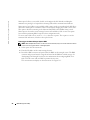
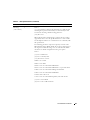
sysinfo
Synopsis
sysinfo [fru | id]
Description
This command retrieves and displays the system information, including field replaceable unit
(FRU) and BMC information for the managed system. See Figure 3-6.
BMC Management Utility
37
www.dell.com | support.dell.com
Subcommands
fru — Returns FRU related information
id — Returns BMC related information
Default Subcommand
If a subcommand is not specified, this command acts the same as sysinfo id. See Figure 3-6.
Figure 3-6. sysinfo Option Example
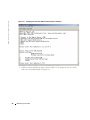
power
Synopsis
power status
power off [-force] | on | cycle | reset
Description
This command is used to display the current power status of the managed system, turn the system
on or off, or reset the system. See Figure 3-7.
38
BMC Management Utility
Subcommands
status — Displays the current power status of the system, the returned value is “on” or “off”.
on — Turns on the managed system.
off — Issues a “graceful shutdown” IPMI command.
NOTE: The off subcommand is not supported on the PowerEdge 7250. You must use the force option to
turn off the system.
cycle — Turns off the system, pauses, then turns the system back on.
reset — Pulses the system reset signal, regardless of the power state.
Options
-force
This option simulates pressing the power button, forcing the system to turn off without shutting
down the operating system.
Default Subcommand
If a subcommand is not specified, this command acts the same as power status.
Figure 3-7. power Option Example
BMC Management Utility
39
www.dell.com | support.dell.com
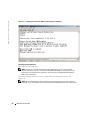
sel
Synopsis
sel status
sel get [ [-begin index1 ] [-end index2 | -max count] ] | [-last n]
sel clear
Description
This command is used to display event log information, display the contents of the event log, and
delete all the event log records. See Figure 3-8.
Subcommands
status — Displays the total number of system event log records.
get — Prints all or part of the event log.
clear — Deletes all the records in the event log.
Options
-begin index1
Specifies the first record to display.
-end
index2
Specifies the last record to display.
-max count
Specifies the maximum number of the records to display.
If the value of the argument count is bigger than the total number of the records, the last record
displayed will be the last one in the event log.
-last n
Specifies the number of records to be displayed, starting from the last record and counting
backwards.
Default Subcommand
If a subcommand is not specified, this command acts the same as sel status.
Display Format
System event log records are displayed using a tabular format. The column headers are: Ordinal
Number, Sensor Number, Sensor Type, and Brief Description. See Figure 3-8.
40
BMC Management Utility
Figure 3-8. sel Option Example
SOL Proxy
SOL Proxy is a simple telnet server. It allows a telnet client to interact with the hardwaredesignated serial port of a remote managed system using the LAN communication channel. See
Figure 3-9. With SOL Proxy, administrators can view and change the BIOS settings over a shared
LAN. In addition, you can also access your managed system’s BMC using SOL Proxy using the Red
Hat Linux serial console and Microsoft’s EMS/SAC interfaces. SOL Proxy does not support inband or serial connection to the managed system’s BMC.
When BIOS console redirection to serial port is enabled on the remote managed system, any
application that uses the BIOS to read from or write to the system console will have its I/O
redirected to the designated serial I/O port. When SOL is activated, the BMC firmware reads any
data written to the serial port and transmits it to the SOL Proxy as LAN packets. SOL Proxy then
forwards the data to the telnet client as TCP/IP packets.
Conversely, any keyboard activity at the telnet client is sent to the BMC by SOL Proxy. BMC then
writes the packets to the system serial I/O port.
NOTE: See "Using Console Redirection" for more information about console redirection, including
hardware and software requirements and instructions for configuring host and client systems to use
console redirection.
BMC Management Utility
41
www.dell.com | support.dell.com
Figure 3-9. SOL Proxy Diagram
The SOL Proxy communication scheme enables the viewing and configuration of the BIOS
settings of a managed system, as well as resetting the managed system remotely using a telnet
client. SOL Proxy is installed as a daemon service and automatically starts each time the system
boots. SOL Proxy can accommodate only one telnet session at a time.
A variety of telnet clients can be used to access SOL Proxy features. For example:
•
In a Windows environment, you can use a Command Prompt window as your console.
However, function keys such as <F1> and <F2> will not operate correctly with this client
except on systems running Windows Server 2003.
•
In a Windows environment, you can also use any telnet application that supports VT100 or
ANSI emulation mode (such as HyperTerminal) as your console. HyperTerminal key
mappings are based on the supported terminal emulation modes and do not support some
useful terminal types. For example, HyperTerminal does not support the “Linux” terminal
mode (a modified VT100 terminal). If you use HyperTerminal to connect to a Red Hat Linux
console (redirected by SOL) the function and arrow keys may not work, based on the “tty”
settings of the remote application.
NOTICE: All versions of the Microsoft Windows operating system include Hilgraeve's HyperTerminal
terminal emulation software. However, the included version does not provide many functions required
during console redirection. Instead, you can use any terminal emulation software that supports VT100 or
ANSI emulation mode. One example of a full VT100 or ANSI terminal emulator that supports console
redirection on your system is Hilgraeve's HyperTerminal Private Edition 6.1 or later.
42
BMC Management Utility
NOTE: When using HyperTerminal, uncheck the Wrap lines that exceed terminal width check box
to avoid console redirected data that may appear to be corrupted or garbled. To uncheck this
feature, click File→ Properties→ Settings→ ASCII Setup…→ Wrap lines that exceed terminal
width.
NOTE: See "Using Console Redirection" for more information about console redirection, including
hardware and software requirements and instructions for configuring host and client systems to
use console redirection.
•
In a Red Hat Linux environment, you can use a shell such as csh or ksh as your console, or you
can use any telnet application supporting VT100 or ANSI emulation mode.
NOTE: HyperTerminal and telnet settings must be consistent with the settings on the managed system.
For example, the baud rates and terminal modes should match.
Using SOL Proxy
Depending on the console you use, there are different steps for accessing SOL Proxy. Throughout
this section, the managed system that SOL Proxy is accessing is referred to as the SOL Proxy Server.
Using the Windows Command Prompt
To connect and use SOL Proxy:
1
Open a Command Prompt window on your management station.
2
Enter the telnet command in the command-line and provide the IP address of the SOL Proxy
Server and the port number you have specified in the SOL Proxy installation (the default
value is 623). Such as:
telnet 192.168.1.24 623
NOTE: The IP address and port number you provide should conform to the ones defined in the SOL
Proxy configuration file. For more details, see “Configuring SOL Proxy with the SOL Proxy
Configuration File.”
3
If prompted for a username, provide the operating system login credentials of SOL Proxy
Server.
4
Provide a password when prompted. SOL Proxy will use this combination of operating system
username and password to authenticate you on SOL Proxy Server. The specific authentication
scheme will depend on the operating system configuration for the SOL Proxy Server.
However, if localhost or an IP address of 127.0.0.1 is used, it is assumed that the user has login
privileges to the current host, and is not prompted for a username and password.
5
After authentication is performed, you will see a login successful message and the SOL Proxy
main menu prompt. You are ready to use SOL Proxy. See "SOL Proxy Main Menu" for further
instructions.
BMC Management Utility
43
www.dell.com | support.dell.com
Using Windows HyperTerminal Console
To connect and use SOL Proxy:
1
Open a HyperTerminal session on your management station.
2
Create a new TCP/IP connection, providing the IP address of SOL Proxy Server and the port
number you have specified in SOL Proxy installation (the default value is 623). The
Emulation mode is VT100 and ANSI.
NOTE: The IP address and port number you provide should conform to the ones defined in the SOL
Proxy configuration file. For more details, see “Configuring SOL Proxy with the SOL Proxy
Configuration File.”
3
Try the newly defined connection by clicking the connect button in the tool bar.
4
If prompted for a username, provide the operating system login credentials of SOL Proxy
Server.
5
Provide a password when prompted. SOL Proxy will use this combination of operating system
username and password to authenticate you on SOL Proxy Server. The specific authentication
scheme will depend on the operating system configuration for the SOL Proxy Server.
However, if localhost or an IP address of 127.0.0.1 is used, it is assumed that the user has login
privileges to the current host, and is not prompted for a username and password.
6
After authentication is performed, you will see a login successful message and the SOL Proxy
main menu prompt. You are ready to use SOL Proxy. See "SOL Proxy Main Menu" for further
instructions.
Using a Red Hat Linux Shell
To connect and use SOL Proxy:
1
Open a Red Hat Linux shell on your management station.
2
Enter the telnet command and provide the IP address of the SOL Proxy Server and the port
number you have specified in SOL Proxy installation. Such as:
telnet 192.168.1.24 623
NOTE: The IP address and port number you provide should conform to the ones defined in the SOL
Proxy configuration file. For more details, see “Configuring SOL Proxy with the SOL Proxy
Configuration File.”
44
3
If prompted for a username, provide the operating system login credentials of SOL Proxy
Server.
4
Provide a password when prompted. SOL Proxy will use this combination of operating system
username and password to authenticate you on SOL Proxy Server. The specific authentication
scheme will depend on the operating system configuration for the SOL Proxy Server.
However, if localhost or an IP address of 127.0.0.1 is used, it is assumed that the user has login
privileges to the current host, and is not prompted for a username and password.
BMC Management Utility
5
After authentication is performed, you will see a login successful message and the SOL Proxy
main menu prompt. You are ready to use SOL Proxy. See "SOL Proxy Main Menu" for further
instructions.
SOL Proxy Main Menu
After the telnet connection with SOL Proxy is successfully established, you are presented with the
following menu of choices. See Figure 3-10.
Figure 3-10. SOL Proxy Main Menu Example
The SOL Proxy main menu allows you to change the SOL settings of a remote managed system’s
BMC, reboot the remote BMC, or activate console redirection.
Selecting menu option 1, Connect to the Remote Server’s BMC, prompts you for the BMC IP
address and BMC login. After entering the required information and making a successful
connection, the internal state SLP is changed to “connected.” If you select menu options 2, 3, or 4,
and the application state is not “connected,” the you are prompted to connect to a BMC.
BMC Management Utility
45
www.dell.com | support.dell.com
Menu option 2 allows you to enable, disable, and configure the SOL defaults, including the
minimum user privilege level required for activating SOL and the communication baud-rate.
Menu options 3 and 4 allow you to establish a SOL remote console session through the SOL Proxy
main menu. Menu option 3 establishes a SOL session without changing the remote system’s state.
This option is ideal for connecting to the Microsoft SAC/EMS or the Red Hat Linux console.
Menu option 4 reboots the remote managed system and establishes a SOL session. This option
best suited for performing BIOS setup and system configuration tasks.
To exit an active SOL session, use the <~><.> character sequence. The sequence is used to
terminate SOL and return you back to the top-level menu.
Connecting to the Remote Managed System’s BMC
NOTE: While multiple SOL sessions can be active at the same time, only one console redirection session
can be active at any given time for a managed system.
1
Select option 1 in the main menu.
2
Enter the IP address of the remote managed system.
3
Provide the BMC username and password for the BMC on the managed system. The BMC
username and password must be assigned and stored in the BMC non-volatile storage. See
"Configuring Your Managed System" for more information about configuring BMC users.
Only one SOL session with one BMC is permitted at one time.
The connection status displays on the main menu. See Figure 3-11.
46
BMC Management Utility
Figure 3-11. Connecting to the Remote System’s BMC
Configuring the SOL for the Remote Managed System
Select option 2 in the main menu.
NOTE: You must be connected to the managed system’s BMC before you can configure the SOL
features. If SOL Proxy is not yet connected to the managed system’s BMC, you are prompted for an IP
address and a username/password combination. See "Connecting to the Remote Managed System’s
BMC" for more information.
The SOL configuration menu appears. According to the current SOL status, the content of the
SOL configuration menu varies:
•
If SOL is already enabled, the current settings are displayed and the user will be presented
with three choices. See Figure 3-12.
BMC Management Utility
47
www.dell.com | support.dell.com
Figure 3-12. Configuring the Serial-Over-LAN for the Remote System, Example 1
•
48
If SOL is currently disabled, the options shown in Figure 3-13 are displayed. Type Y to enable
SOL or N to keep SOL disabled. See Figure 3-13.
BMC Management Utility
Figure 3-13. Configuring the Serial-Over-LAN for the Remote System, Example 2
•
If SOL is enabled, two BMC settings are displayed:
–
The communication baud-rate between the system serial port and the BMC.
–
The minimum BMC user privilege level required for activating console redirection.
SOL Proxy displays a list of valid values for each feature, as well as the current value of the
feature enclosed in a pair of brackets. You can select the number before a value to set it as the
new setting, or press <Enter> to leave the BMC settings unchanged. If changes are made to
the BMC settings, you are asked to confirm your changes. The new BMC settings are then
displayed. See Figure 3-14.
BMC Management Utility
49
www.dell.com | support.dell.com
Figure 3-14. Configuring the Serial-Over-LAN for the Remote System, Example 3
Activating Console Redirection
Select option 3 in the main menu.
NOTE: You must be connected to the managed system’s BMC before you can configure the SOL
features. If SOL Proxy is not yet connected to the managed system’s BMC, you are prompted for an IP
address and a username/password combination. See "Connecting to the Remote Managed System’s
BMC" for more information.
The remote manages system’s text console is redirected to your management station. See
Figure 3-15.
NOTE: BIOS Console Redirection must be enabled on the managed system and correctly configured
before SOL can be successfully activated. See "Configuring Your Managed System" for more information.
50
BMC Management Utility
Figure 3-15. Console Redirection Example
Rebooting the Managed System and Activating Console Redirection
Select option 4 in the main menu.
NOTE: You must be connected to the managed system’s BMC before you can configure the SOL
features. If SOL Proxy is not yet connected to the managed system’s BMC, you are prompted for an IP
address and a username/password combination. See "Connecting to the Remote Managed System’s
BMC" for more information.
The power state of the remote managed system is checked. If power is on, you are asked to decide
between a graceful or forceful shutdown.
Next, the power state is monitored until the status changes to off. Console redirection begins, and
the remote managed system text console is redirected to your management station. Use the escape
character sequence <~><.> to terminate it and return to the top-level menu.
While the manages system reboots, you can enter the BIOS system setup program to view or
configure BIOS settings. See Figure 3-16.
NOTE: Before activating the console redirection, you must first enable the console redirection features.
See "Configuring Your Managed System" for more information.
BMC Management Utility
51
www.dell.com | support.dell.com
Figure 3-16. Reboot Example
Getting Help
Select option 5 in the main menu to display detailed descriptions for each option. See Figure 3-17.
52
BMC Management Utility
Figure 3-17. Sample Help Screen
Exit
Select option 6 to end your telnet session and disconnect from SOL Proxy.
Configuring SOL Proxy with the SOL Proxy Configuration File
SOL Proxy must be correctly configured and running before establishing telnet connection.
There are certain SOL parameters that the user can set by modifying the solproxy.cfg file. The
parameters and their descriptions are as follow:
Comments
Any line starting with a “#” is treated as a comment. For example:
#The file is an example.
BMC Management Utility
53
www.dell.com | support.dell.com
IP address
ip — specifies the specific IP address used to connect to the SOL Proxy. This item defines what
kind of connection can be accepted to establish a SOL Proxy telnet session. There are three
possible values:
•
INADDR_ANY — SOL Proxy accepts the telnet request to any system.
•
127.0.0.1 — SOL Proxy accepts the telnet request to the localhost.
•
IP address — SOL Proxy accepts the telnet request to the specified IP address.
For example:
ip=INADDR_ANY
Port binding
port — specifies the port at which the SOL Proxy listens for incoming connections. By default, the
port is set to 623 and can be modified by the user.
This item defines the port when you telnet SOL Proxy. If this item is absent, 623 is set as the
default port. For example:
port=623
Session Timeout
session_timeout — specifies the time in minutes before the SOL Proxy session times out.
If there is no keyboard activity for the specified timeout period, the telnet session and the SOL
session will be closed. The timeout value is specified in minutes and can be changed during SOL
Proxy installation. For example:
session_timeout=30
Power-off Timeout
power_off_timeout — specifies the time in seconds before the SOL Proxy gives up polling for the
managed system's power status. If the SOL Proxy issues the power off command and the system
does not power off within the specified interval, the SOL Proxy returns with a message, indicating
that the SOL Proxy was unable to power off the system due to the timeout interval.
NOTE: When Reboot and Activate Console Redirection is selected and power for the remote managed
system is on, a power off IPMI command is issued. The power status is then continually monitored until
the power status reports “off.” If power status remains “on” longer than this timeout period, Reboot and
Activate Console Redirection reports an error and returns to the top-level menu. This timeout value is
specified in seconds and can be changed during SOL Proxy installation.
For example:
power_off_timeout=60
54
BMC Management Utility
Retry Interval
retry_interval — specifies the period of time in seconds that the BMC waits before it retries
sending a packet. The retry_interval unit is half a second. Therefore, a value of 2 means that the
software waits one second for the BMC to respond before it tries to resend the packet, a value of 4
means that it waits two seconds, and so on. For example:
retry_interval=2
Retry Count
retry_count — specifies the maximum number of times that the software retries sending a packet if
it does not receive a response from the BMC. Before each retry, the software waits for the interval
specified by the retry_interval parameter. For example:
retry_count=10
BMC Management Utility
55
56
BMC Management Utility
www.dell.com | support.dell.com
4
Known Issues and Frequently Asked
Questions
Q: Do IPMI Shell commands correspond one-to-one to IPMI commands?
A: IPMI Shell provides only the most useful IPMI commands. It includes a definitive set of
commands that can be used to accomplish the most common management tasks. Therefore, IPMI
Shell commands may not correspond one-to-one to IPMI commands.
Q: Can I manage a system by accessing multiple IPMI instances simultaneously?
A: Yes, you can manage a system by accessing multiple IPMI instances at the same time as long as
your system’s BMC supports more than one concurrent connection.
Q: Can I manage a system by accessing multiple SOL Proxy connections simultaneously?
A: No, a system can have only one SOL Proxy connection at any time. This connection is
established when you choose either option 3 or 4 in the main menu. However, if you select option 1
to connect to the remote system, only an IPMI connection is established. In this case, multiple
clients can simultaneously use option 1 in the SOL proxy main menu to connect to the same
system (See the previous question).
Q: How do I unlock an SOL session occupied by another user?
A: Your system’s BMC only supports one SOL session at a time. To unlock a SOL session, you must
reboot the system to terminate the other user’s session. Only BMC users with operator or
Administrator IPMI privileges can reboot the system.
Q: Why can’t I enter the BIOS setup interface during the process of remote system rebooting?
A: When you select item 2, Reboot and activate console redirection, in the SOL Proxy main
menu, the managed system is rebooted first. Press <F2> to enter the BIOS setup interface, if the
telnet client you are using supports VT100 or ANSI.
Known Issues and Frequently Asked Questions
57
www.dell.com | support.dell.com
Q: Why can’t I connect to a console using the terminal emulation software included with my
Microsoft Windows operating system?
A: The version of HyperTerminal included with Windows does not provide many functions
required during console redirection. Either upgrade to HyperTerminal Private Edition 6.1 or later,
or select any other terminal emulation software that supports VT100 or ANSI emulation mode.
Q: I performed a Reboot and Activate Console Redirection command using SOL Proxy, but the
option to press <F2> to enter the BIOS setup never appeared.
A: When the network switch has spanning-tree enabled, it takes about 30-40 seconds for the
spanning-tree check to make sure there are no loops in the network. During this time, packet
forwarding by the switch is blocked. Therefore, the software cannot communicate with the BMC
until the spanning tree check is complete.
Disable spanning-tree on the network switch and try performing a Reboot and Activate Console
Redirection command using SOL Proxy again. You should now be able to enter BIOS setup by
pressing <F2>.
58
Known Issues and Frequently Asked Questions
A
BMC Management Utility Error Codes
In case of a functional failure, an error message will be printed to stderr. The text of the error
message is listed in the Message column in Table A-1. Errors will always be printed in a parsable
format. For example:
Error (<hex-code>):<message>!
Example: Error(0xC1):Invalid Command!
Table A-1. BMC Management Utility Error Codes
Code
Classification
Message
Description
A1h
Connection
errors.
Connection timeout.
BMC not responding.
IPMI Error
Invalid authentication type. Authentication Type
Error.
A2h
A3h
A5h
BDh
Communication
errors.
Authorization
errors.
Initialization
errors.
Communication Error.
Network stack or serial
communication error.
Data Error.
Data packet format error. 0xC6,
0xC7,
0xC8,
0xCA
Not connected.
Not connected to a
remote server yet.
Insufficient privilege for
command.
Insufficient privilege
level to execute
command.
0xD4
Login not authorized.
Invalid BMC
username/password.
0x86
Authentication failure.
Request for a session
from the local or remote
proxy was rejected.
Access denied.
Trying to access the proxy
from a forbidden IP
address.
Unknown language.
Unknown Language
code.
BMC Management Utility Error Codes
59
www.dell.com | support.dell.com
Table A-1. BMC Management Utility Error Codes (continued)
Code
A6h
Classification
Syntax errors.
Message
Description
Invalid IP address.
IP resolving error.
Session buffer limit
exceeded.
Length exceeds the limit
of telnet input.
Command syntax error.
Unable to parse
command.
Unrecognized command.
Unrecognized
Command.
Time format is incorrect.
The time is not correct.
Conflicting option.
Conflicting option (-last
and -max).
Invalid parameter.
Invalid Parameter.
Parameter out of range.
Parameter out of range.
Parameter out of range (1255)
The value is out of range
(1-255).
Parameter out of range(165535).
The value is out of range
(1-65535).
Invalid data field.
Invalid data field.
Invalid index value.
Index cannot be zero or a
negative number.
First index larger than the
last.
The first index is larger
than the last.
A8h
A7h
Parameter value
errors.
IPMI Error
0xC9
0xCC
First index larger than total The first index is larger
SEL records.
than the total SEL
records.
A8h
60
H/W or F/W
errors.
BMC Management Utility Error Codes
Unsupported command.
Unsupported Operation. 0xC1
Sensor not present.
Request sensor, data, or
record not present.
Sensor command error.
Command illegal for
0xCD
specified sensor or record
type.
Firmware error.
Command response
could not be provided.
0xCB
0xCE
Table A-1. BMC Management Utility Error Codes (continued)
Code
A9h
Classification
Processing errors
(transient errors
that may
disappear upon
retry of
command).
Message
Description
Destination error.
Cannot deliver request to 0xD3
destination.
Device error.
Device specific (OEM)
errors.
0x01–0x7E
BMC busy.
BMC out of processing
resources.
0xC0
Destination timeout Error. BMC timeout while
processing command
AEh
AFh
0xC3
BMC out of storage space.
BMC out of storage space 0xC4
required to process
command.
Invalid reservation ID.
Invalid reservation ID.
0xC5
Duplicate command.
Cannot execute
duplicated request.
0xCF
SDR busy.
Sensor Data Record
Repository in update
mode.
0xD0
Device busy.
Device in firmware
update mode.
0xD1
BMC unavailable.
BMC initialization in
progress.
0xD2
Bad BMC state.
Request not supported in 0xD5
present BMC state.
BMC out of sessions.
No session slots are
available for connection
request.
0x81,
0x82,
0x83
Invalid Logical Unit
Number (LUN) in
request.
0xC2
Unspecified error.
Unspecified error.
0xFF
Unknown error.
Unknown error.
Unexpected IPMI Invalid LUN.
errors.
Unknown error
IPMI Error
BMC Management Utility Error Codes
61
www.dell.com | support.dell.com
62
BMC Management Utility Error Codes
B
Using Console Redirection
Console redirection allows you to manage a host (local) system from a client (remote) system by
redirecting keyboard input and text output through a serial port. You cannot redirect graphic
output. You can use console redirection for tasks such as configuring BIOS settings.
You can also connect the client system to a port concentrator that can access numerous host
systems using a shared modem. After logging into the port concentrator, you can select a host
system to manage using console redirection.
This section describes the most basic connection possible: connecting systems using a null-modem
serial cable, which directly connects the serial ports on two systems.
Hardware Requirements
•
An available serial (COM) port on the host system
•
An available serial (COM) port on a client system
This port must not conflict with any other ports on the client system.
•
A null-modem serial cable to connect the host system to the client system
Software Requirements
•
VT 100/220 or ANSI terminal emulation with a window size of 80 x 25 characters
•
9600, 19.2 K, 57.6 K, or 115.2 K bps using serial (COM) ports
•
Ability to create keyboard command macros (recommended)
All versions of the Microsoft® Windows® operating system include Hilgraeve's HyperTerminal
terminal emulation software. However, the included version does not provide many functions
required during console redirection. Either upgrade to HyperTerminal Private Edition 6.1 or later,
or select any terminal emulation software that supports VT100 or ANSI emulation mode.
Configuring the Host System
Configure console redirection on the host (local) system through the System Setup utility (see
"BIOS Configuration"). The Console Redirection screen allows you to enable or disable the
console redirection feature, select the remote terminal type, and enable or disable console
redirection after booting.
Using Console Redirection
63
www.dell.com | support.dell.com
Configuring the Client System
After configuring the host system, configure the ports and terminal settings for the client (remote)
system.
NOTE: The examples in this section assume that you have upgraded to Hilgraeve's HyperTerminal
Private Edition 6.1 or later. If you are using other terminal emulation software, see the documentation for
that software.
Configuring the Serial Port
1
Click the Start button, point to Programs→ Accessories→ Communications, and then click
HyperTerminal.
2
Enter a name for the new connection, select an icon, and then click OK.
3
From the Connect to dropdown menu, select an available COM port, and then click OK.
After you select an available COM port, the COM port properties window appears.
4
Configure the port with the following settings:
•
Set Bits per second.
Console redirection supports only 9600, 19.2 K, 57.6 K, or 115.2 K bps.
5
•
Set Data bits to 8.
•
Set Parity to None.
•
Set Stop bits to 1.
•
Set Flow control to Hardware.
Click OK.
Configuring the Terminal Settings
1
In HyperTerminal, click File, click Properties, and then click the Settings tab.
2
Ensure that the Function, arrow, and Ctrl keys act as field is set to Terminal Keys.
3
Ensure that the Backspace key sends field is set to Ctrl+H.
4
Change the Emulation setting from Auto detect to ANSI or VT 100/220.
Ensure that this setting is the same as the setting you selected for the Console Redirection
option on the host system.
5
Click Terminal Setup.
A setting for the number of rows and columns appears.
6
Change the number of rows from 24 to 25 and leave the number of columns at 80.
If you do not have these settings, you must upgrade your terminal emulation software.
7
64
Click OK twice.
Using Console Redirection
Managing the Host System Remotely
After you configure the host and client systems (see "Configuring the Host System" and
"Configuring the Client System"), you can use console redirection to restart a host system or to
change a host system's configuration settings.
1
Reboot the host system using the client system.
See "Configuring Special Key Functions" for instructions.
2
When the host system begins to boot, use console redirection to:
•
Enter the System Setup utility
•
Enter the SCSI setup menus
•
Update firmware and BIOS (flash the system)
•
Run utilities on the utility partition
Configuring Special Key Functions
Console redirection uses ANSI or VT 100/220 terminal emulation, which is limited to basic ASCII
characters. Function keys, arrow keys, and control keys are not available in the ASCII character set,
and most utilities require function keys and control keys for ordinary operations. However, you can
emulate a function key or control key using a special key sequence, called an escape sequence.
An escape sequence starts with an escape character. You can enter this character in different ways,
depending on the requirements of your terminal emulation software. For example, 0x1b and
<Esc> each represent the escape character. In HyperTerminal, you can create macros by selecting
Key Macros from the View menu. You can assign a macro to almost any key for almost any key
combination. Create a macro to represent each function key.
Table B-1 lists the escape sequences that represent a special key or function.
NOTE: When creating macros in HyperTerminal, press <Insert> before <Esc> to signify that you are
sending an escape sequence rather than escaping out of the dialog box. If you do not have this function,
you must upgrade HyperTerminal.
NOTE: Escape-sequence key combinations listed in Table B-1 are case-sensitive. For example, to
generate the character <A> you must press <Shift><a>.
Table B-1. Supported Escape Sequences
Key(s)
Supported Sequence
Terminal Emulation
<Up arrow>
<Esc><[><A>
VT 100/220, ANSI
<Down arrow>
<Esc><[><B>
VT 100/220, ANSI
<Right arrow>
<Esc><[><C>
VT 100/220, ANSI
<Left arrow>
<Esc><[><D>
VT 100/220, ANSI
Using Console Redirection
65
www.dell.com | support.dell.com
Table B-1. Supported Escape Sequences (continued)
Key(s)
Supported Sequence
Terminal Emulation
<F1>
<Esc><O><P>
VT 100/220, ANSI
<F2>
<Esc><O><Q>
VT 100/220, ANSI
<F3>
<Esc><O><R>
VT 100/220, ANSI
<F4>
<Esc><O><S>
VT 100/220, ANSI
<F5>
<Esc><O><T>
VT 100, ANSI
<F6>
<Esc><O><U>
VT 100, ANSI
<Esc><[><1><7><~>
VT 100/220
<Esc><O><V>
VT 100, ANSI
<Esc><[><1><8><~>
VT 100/220
<Esc><O><W>
VT 100, ANSI
<Esc><[><1><9><~>
VT 100/220
<Esc><O><X>
VT 100, ANSI
<Esc><[><2><0><~>
VT 100/220
<Esc><O><Y>
VT 100, ANSI
<Esc><[><2><1><~>
VT 100/220
<Esc><O><Z>
VT 100, ANSI
<Esc><[><2><3><~>
VT 100/220
<Esc><O><A>
VT 100, ANSI
<Esc><[><2><4><~>
VT 100/220
<Home>
<Esc><[><1><~>
<Esc><h>
VT 220
ANSI
<End>
<Esc><[><4><~>
VT 220
<Esc><k>
ANSI
<Delete>
<Esc><[><3><~>
VT 220
<Esc><–>
ANSI
<Esc><[><3><~>
VT 220
<Esc><–>
ANSI
<Esc><[><5><~>
VT 220
<Esc><Shift><?>
ANSI
<Esc><[><6><~>
VT 220
<Esc></>
ANSI
<F7>
<F8>
<F9>
<F10>
<F11>
<F12>
<Delete>
<Page Up>
<Page Down>
66
Using Console Redirection
Table B-1. Supported Escape Sequences (continued)
Key(s)
Supported Sequence
Terminal Emulation
<Shift><Tab>
<Esc><[><Z>
VT 100
<Esc><[><0><Z>
VT 220
<Esc><[><Shift><z>
ANSI
After creating macros for the keys listed in Table B-1, press <F1> on the client system's keyboard
during terminal emulation to send the escape sequence <Esc><O><P> to the host system. The
host system then interprets the sequence as <F1>.
Additional escape sequences may be required by certain utilities or functions on the host system.
Create macros for the additional sequences listed in Table B-2.
NOTE: Escape-sequence key combinations listed in Table B-2 are case-sensitive. For example, to
generate the character <A> you must press <Shift><a>.
.
Table B-2. Additional Escape Sequences
Key(s)
Supported Sequence
<Ctrl><Alt><Del>
(Reboot host system)
<Esc><R><Esc><r><Esc><R>
<Alt><x>
<Esc><X><X>
<Ctrl><H>
<Esc><Ctrl><H>
<Ctrl><I>
<Esc><Ctrl><I>
<Ctrl><J>
<Esc><Ctrl><J>
<Ctrl><M>
<Esc><Ctrl><M>
<Ctrl><2>
<Esc><Ctrl><2>
Using Console Redirection
67
68
Using Console Redirection
www.dell.com | support.dell.com
C
Terminal Mode Commands
Terminal mode allows you to directly interface to the server's Baseboard Management Controller
(BMC) using a serial port connection and execute text-based commands. Two types of text
commands are supported:
•
A limited selection of text commands
•
Standard binary IPMI 1.5 hex-ASCII commands
Using the terminal mode feature you can do the following:
•
Power the server on or off
•
Reset the server
•
Retrieve the server's health status
•
Configure and retrieve the server management subsystems boot options
•
Configure and retrieve the BMC's terminal mode configuration
•
Execute any platform supported binary command specified in the Intelligent Platform
Management Interface (IPMI) version 1.5 specification using the hex-ASCII format
NOTE: Many of the Terminal Mode features described in this section require an extensive knowledge of
IPMI to use. It is strongly recommended that Terminal Mode users have an advanced
understanding of IPMI before using the commands documented in this section.
Security Information
Access to the BMC using terminal mode is governed by the proper setup of user names and
password in the SMU. A session must be established with the BMC prior to accepting any terminal
mode commands. A limited selection of text commands and binary hex-ASCII commands that are
assigned the lowest IPMI privilege level are available prior to session establishment with the BMC.
See "Configuring Your Managed System with the System Maintenance Utility (SMU)" for more
information.
Since the terminal mode password is sent using clear text, it is highly desirable that the terminal
mode session takes place in a secure location over a secure link, preferably via a direct connection.
Connection via a modem is supported but not recommended.
Syntax
Terminal mode messages follow the general syntax below:
[<message data>]<newline sequence>
Terminal Mode Commands
69
www.dell.com | support.dell.com
Each terminal mode message must be preceded with the left bracket "start” character and must be
ended with a right bracket “stop” character and the appropriate input new-line sequence.
No input characters are accepted until the start character has been received.
Terminal mode text commands are case sensitive, but hex-ASCII commands can either use upper
or lower case letters for ASCII representations of hex digits.
Command Length
Terminal mode messages are limited to a maximum length of a 122 characters. This includes the
left and right brackets, but not control characters.
Character Support
Terminal mode messages are allowed to be composed of standard printable ASCII characters. All
other characters are treated as illegal characters.
Special Character Handling — <ESC> character
The <ESC> character can be used to delete an entire message prior to submission to the BMC for
processing. If line editing is enabled, and the <ESC> key is followed by an input newline
sequence, the BMC responds by outputting an output newline sequence. Otherwise, the BMC
goes back to looking for the start character.
Special Character Handling — <DEL> or <BKSP> character
The <BKSP> or <DEL> key can be used to delete the last character entered if the message has
not been submitted to the BMC yet.
Special Character Handling — Line Continuation character
Long IPMI messages can be split across multiple lines by using the line continuation
<BACKSLASH> character followed immediately by an input newline sequence. Line
continuation character usage is supported for both text and hex-ASCII commands.
Special Character Handling — Illegal characters
Any illegal characters received by the BMC clears the message in progress and forces the BMC back
to looking for the start character.
Hex-ASCII Command Format
Binary IPMI commands are sent and received as a series of case insensitive hex-ASCII pairs, where
each is optionally separated from the preceding pair by a single <space> character. The following
is an example of a binary IPMI request message:
[18 00 22]<newline sequence>
70
Terminal Mode Commands
The software ID and LUN for the remote console are fixed and implied by the command. The
SWID for messages to the remote console is always 47h, and the Logical Unit Number
(LUN) is 00b.
Instead, there is a "bridge" field that is used to identify whether the message should be routed to
the BMC’s bridged message tracking or not. See "Terminal Mode IPMI Message Bridging" for more
information.
Table C-1. Terminal Mode Request to BMC
Byte
Explanation
1
[7:2] – Net Function (even)
[1:0] – Responder’s LUN
2
[7:2] – Requester’s Sequence Number
[1:0] – Bridge field
3
Command Number
4:N
Data
Table C-2. Terminal Mode Response from BMC
Byte
Explanation
1
[7:2] – Net Function (odd)
[1:0] – Responder’s LUN
2
[7:2] – Requester’s Sequence Number
[1:0] – Bridge field
3
Command Number
4
Completion Code
5:N
Data
Text Command Format
Text commands do not support the bridging and sequence number fields present in the hex-ASCII
commands, are case sensitive, and are preceded by a prefix consisting of the string SYS.
Examples
Hex-ASCII command example (IPMI Reset Watchdog Cmd):
[18 00 22]<CR>
[1C 00 22 00]<CR-LF>
Terminal Mode Commands
71
www.dell.com | support.dell.com
Text command example:
[SYS TMODE]<CR>
[OK TMODE]<CR-LF>
Terminal Mode IPMI Message Bridging
Terminal mode supports the ability to bridge IPMI messages to another interface when binary
hex-ASCII IPMI commands are used. The message bridge is determined by the following: the
bridge field, whether the message is a request or a response, the message direction with respect to
the BMC and the LUN. Table C-3 lists the supported BMC combinations for IPMI message
bridging. Any other combinations are unsupported.
Note that IPMI messages to and from the system interface are transferred using the BMC SMS
(System Management Software) LUN, 10b, and with the bridge field set to 00b.
Table C-3. Supported BMC Combinations for IPMI Message Bridging
72
Bridge
Field
Request/
Response
Message
Direction (to BMC)
LUN
Message
Interpretation
00b
Request
In
00b,
01b,
11b
Remote Console request to BMC functionality
Message is a request from the remote console to
the BMC.
00b
Response
Out
00b,
01b,
11b
Response to Remote Console from BMC
functionality Message is a response to an earlier
request from the remote console to the BMC.
00b
Request
In
10b
Remote Console request to SMS Message is a request
from the remote console to SMS via the Receive
Message Queue.
00b
Response
Out
10b
SMS Response to Remote Console Message is a
response to an earlier request from SMS.
01b
Response
Out
Any
Response to earlier Bridged Request from Remote
Console Message is the asynchronous response from
an earlier bridged request that was encapsulated in a
Send Message command issued to the BMC by the
remote console.
Terminal Mode Commands
Table C-4. Terminal Mode Text Commands
Command
Switches
Description
SYS PWD
-U USERNAME
<password>
Used to activate a terminal mode session. USERNAME
corresponds to the ASCII text for the username. <password>
represents a printable password (up to 16 characters). If
<password> is not provided, then a Null password (all binary 0’s)
is submitted. Passwords are case sensitive.
Either the SYS PWD command (or Activate Session IPMI
message) must be successfully executed before any command or
IPMI messages are accepted. Note that a modem connection may
be automatically dropped if multiple bad passwords are entered.
-N <password>
-N represents a Null username. <password> represents a printable
password (up to 16 characters). If <password> is not provided,
then a Null password (all binary 0’s) is submitted. Passwords are
case sensitive.
Either the SYS PWD command (or Activate Session IPMI
message) must be successfully executed before any command or
IPMI messages are accepted. Note that a modem connection may
be automatically dropped if multiple bad passwords are entered.
-X
-X immediately logs out any presently active session. Entering an
invalid password with -U or -N also has the same effect.
SYS TMODE
Used as a no-op confirm that Terminal Mode is active. The BMC
returns an OK response followed by TMODE.
SYS SET BOOT
XX YY ZZ AA BB
Sets the boot flags to direct a boot to the specified device following
the next IPMI command or action initiated reset or power-on.
XX…BB represent five hex-ASCII encoded bytes, which are the
boot flags parameter in the Boot Option Parameters. See Table C-5
for more information.
Upon receiving this command, the BMC automatically sets the
valid bit in the boot options and sets all the Boot Initiator
Acknowledge data bits to 1b.
Terminal Mode Commands
73
www.dell.com | support.dell.com
Table C-4. Terminal Mode Text Commands (continued)
Command
Switches
SYS SET
BOOTOPT XX
YY…NN
Description
This is essentially a text version of the IPMI Set System Boot
Options command. It allows any of the boot option parameters to
be set, not just the boot flags. XX YY…NN represent the hexASCII encoding for the data bytes that are passed in the Set
System Boot Options request.
See Table C-5 for more information.
XX — Parameter valid.
[7] — 1b = Mark parameter invalid / locked.
0b = Mark parameter valid / unlocked.
[6:0] — Boot option parameter selector .
YY…NN — Boot Option Parameter Data.
Passing 0-bytes of parameter data allows the parameter valid bit to
be changed without affecting the present parameter setting. See
Table C-5 for more information.
SYS GET
BOOTOPT XX
YY ZZ
This is essentially a text version of the IPMI Get System Boot
Options command. It allows any of the boot option parameters to
be retrieved.
XX YY ZZ represents the hex-ASCII for the data bytes that are
passed in the Get System Boot Options request.
The BMC returns the data from the command in hex-ASCII
format. See Table C-5 for more information.
XX—Parameter selector.
[7]—Reserved.
[6:0]—Boot option parameter selector.
YY—Set Selector.
[7:0]—Selects a particular block or set of parameters under the
given parameter selector.
Write as 00h if parameter does not use a Set Selector.
ZZ—Block Selector.
Selects a particular block within a set of parameters
Write as 00h if parameter does not use a Block Selector.
NOTE: There are no IPMI-specified Boot Options parameters that
use the block selector. However, this field is provided for consistency
with other configuration commands and as a placeholder for future
extension of the IPMI specification.
74
Terminal Mode Commands
Table C-4. Terminal Mode Text Commands (continued)
Command
Switches
SYS SET TCFG
Description
Returns the Terminal Mode Configuration bytes where XX and YY
represent hex-ASCII encoding for the volatile version of data bytes
1 and 2 as specified in Table C-6, and AA BB represent hex-ASCII
encoding of the non-volatile version.
V:XX Output termination sequence>
N:AA BB <output termination sequence>
-V XX YY
This command sets the volatile Terminal Mode Configuration. XX
and YY represent hex-ASCII encoding for data bytes 1 and 2 as
specified in Table C-6. The BMC returns the same output as for
SYS SET TCFG, above.
-N XX YY
This command sets the non-volatile Terminal Mode
Configuration. XX and YY represent hex-ASCII encoding for data
bytes 1 and 2 as specified in Table C-6. The BMC returns the same
output as for SYS SET TCFG, above.
SYS RESET
Directs the BMC to perform an immediate system hard reset.
SYS POWER
OFF
Directs the BMC to perform an immediate system power off.
SYS POWER ON
Causes the BMC to initiate an immediate system power on.
Terminal Mode Commands
75
www.dell.com | support.dell.com
Table C-4. Terminal Mode Text Commands (continued)
Command
Switches
SYS HEALTH
QUERY
Description
Causes the BMC to return a high level version of the system health
status in "terse" format. The BMC returns a string with the
following format if the command is accepted.
PWR:zzz H:xx T:xx V:xx PS:xx C:xx D:xx S:xx O:xx
Where:
PWR is system POWER state.
H is overall Health.
T is Temperature.
V is Voltage.
PS is Power Supply subsystem.
F is cooling subsystem (Fans).
Dis Hard Drive / RAID Subsystem.
S is physical Security.
O is Other (OEM).
zzz is: ON, OFF (soft-off or mechanical off), SLP (sleep - used
when sleep level cannot be distinguished), S4, S3, S2, S1, ??
(unknown).
and xx is: ok, nc, cr, nr, uf, or ?? where:
ok = OK (monitored parameters within normal operating ranges).
nc = non-critical ("warning": hardware outside
normal operating range).
cr = critical ("fatal": hardware exceeding specified
ratings).
nr = non-recoverable ("potential damage": system
hardware in jeopardy or damaged).
uf = unspecified fault (fault detected, but severity unspecified).
?? = status not available/unknown (typically because system power
is OFF).
76
Terminal Mode Commands
Table C-4. Terminal Mode Text Commands (continued)
Command
Switches
Description
SYS HEALTH
QUERY
-V
Causes the BMC to return a high level version of the system health
status in multi-line "verbose" format. The BMC returns a string of
the following format:
SYS Health:xx<output termination sequence>.
Power: ON, OFF (soft-off or mechanical off), SLEEP (sleep - used
when can't distinguish sleep level), S4, S3, S2, S1, Unknown.
Temperature:xx<output termination sequence>.
Voltage:xx<output termination sequence>.
PowerSystem:xx<output termination sequence>.
Cooling:xx<output termination sequence>.
Drives:xx<output termination sequence>.
Security:xx<output termination sequence>.
Other:xx<output termination sequence>.
Where xx is:
OK (monitored parameters within normal operating ranges).
Non-critical ("warning": hardware outside normal operating
range).
Critical ("fatal" :hardware exceeding specified ratings).
Non-recoverable ("potential damage": system hardware in jeopardy
or damaged).
Unspecified fault (fault detected, but severity unspecified).
Unknown (status not available/unknown (typically because system
power is OFF).
Boot Option Parameters
The designation, semi-volatile means that the parameter will be kept across system power cycles,
resets, system power on/off, and sleep state changes, but will not be preserved if the management
controller loses standby power or is cold reset. Parameters designated as semi-volatile are initialized
to 0’s upon controller power up or hard reset, unless otherwise specified.
IPMI allows software to use the boot initiator mailbox as a way for a remote application to pass
OEM parameters for additional selection of the boot process and direction of the startup of postboot software. If additional parameters are not included, the system boots the primary/firstscanned device of the type specified.
Terminal Mode Commands
77
www.dell.com | support.dell.com
Table C-5. Boot Option Parameters
Parameter
Number
Parameter Data (non-volatile unless otherwise noted)
Set In Progress
0
Data 1 - This parameter is used to indicate when any of the
following parameters are being updated, and when the updates are
completed. The bit is primarily provided to alert software that
some other software or utility is in the process of making changes
to the data. The change shall take effect when the write occurs.
(volatile)
[7:2] -Reserved.
[1:0] -00b = Set complete. If a system reset or transition to
powered down state occurs while "set in progress" is active, the
BMC goes to the "set complete" state. If rollback is implemented,
going directly to "set complete" without first doing a "commit
write" causes any pending write data to be discarded.
01b = Set in progress. This flag indicates that some utility or other
software is presently doing writes to parameter data. It is a
notification flag only, it is not a resource lock. The BMC does not
provide any interlock mechanism that would prevent other
software from writing parameter data while.
10b = Reserved.
11b = Reserved.
Service partition
selector
1
Data 1
[7:0] - Service partition selector. This value is used to select which
service partition BIOS should boot using. This document does not
specify which value corresponds to a particular service partition.
(semi-volatile)[
00h = Unspecified.
Service partition
scan
2
(semi-volatile)[
Data 1
[7:2] - Reserved.
[1] -1b = Request BIOS to scan for specified service partition.
BIOS clears this bit after the requested scan has been performed.
[0] -1b = Service Partition discovered. The BIOS sets this bit to
indicate it has discovered the specified service partition. The BIOS
must clear this bit on all system resets and power ups, except when
a scan is requested.
78
Terminal Mode Commands
Table C-5. Boot Option Parameters (continued)
Parameter
Number
BMC boot flag
valid bit clearing
(semi-volatile)
3
Parameter Data (non-volatile unless otherwise noted)
Data 1 - BMC boot flag valid bit clearing. Default = 0000b.
[7:5] - Reserved.
[4] - 1b = Do not clear valid bit on reset/power cycle caused by
PEF.
[3] - 1b = Do not automatically clear boot flag valid bit if IPMI
Chassis Control command not received within 60-second time-out
(countdown restarts when a IPMI Chassis Control command is
received).
[2] - 1b = Do not clear valid bit on reset/power cycle caused by
watchdog timeout.
[1] - 1b = Do not clear valid bit on pushbutton reset / soft-reset
(for example, <Ctrl>-<Alt>-<Del>).
[0] - 1b = Do not clear valid bit on power up via power pushbutton
or wake event.
Terminal Mode Commands
79
www.dell.com | support.dell.com
Table C-5. Boot Option Parameters (continued)
Parameter
Number
Parameter Data (non-volatile unless otherwise noted)
Boot info
acknowledge
4
These flags are used to allow individual parties to track whether
they have already seen and handled the boot information.
Applications that deal with boot information should check the
boot info and clear their corresponding bit after consuming the
boot options data.
(semi-volatile)
Data 1: Write Mask (write-only—This field is returned as 00h
when read. This is to eliminate the need for the BMC to provide
storage for the Write Mask field.)
[7] - 1b = enable write to bit 7 of Data field.
[6] - 1b = enable write to bit 6 of Data field.
[5] - 1b = enable write to bit 5 of Data field.
[4] - 1b = enable write to bit 4 of Data field.
[3] - 1b = enable write to bit 3 of Data field.
[2] - 1b = enable write to bit 2 of Data field.
[1] - 1b = enable write to bit 1 of Data field.
[0] - 1b = enable write to bit 0 of Data field.
Data 2: Boot Initiator Acknowledge Data.
The boot initiator should typically write FFh to this parameter
prior to initiating the boot. The boot initiator may write 0s if it
wants to intentionally direct a given party to ignore the boot info.
This field is automatically initialized to 00h when the management
controller is first powered up or reset.
[7] - reserved. Write as 1b. Ignore on read.
[6] - reserved. Write as 1b. Ignore on read.
[5] - reserved. Write as 1b. Ignore on read.
[4] - 0b = OEM has handled boot info.
[3] - 0b = SMS has handled boot info.
[2] - 0b = OS / service partition has handled boot info.
[1] - 0b = OS Loader has handled boot info.
[0] - 0b = BIOS/POST has handled boot info.
80
Terminal Mode Commands
Table C-5. Boot Option Parameters (continued)
Parameter
Number
Parameter Data (non-volatile unless otherwise noted)
Boot flags
5
Data 1
(semi-volatile)
[7] - 1b = Boot flags valid. The bit should be set to indicate that
valid flag data is present. This bit may be automatically cleared
based on the boot flag valid bit clearing parameter.
[6:0] - Reserved
BIOS support for the following flags is optional. If a given flag is
supported, it must cause the specified function to occur in order
for the implementation to be considered to be in conformity with
this specification.
The following parameters represent temporary overrides of the
BIOS default settings. BIOS should only use these parameters for
the single boot where these flags were set. If the bit is 0b, BIOS
should use its default configuration for the given option.
Data 2
[7]—1b = CMOS clear.
[6]—1b = Lock Keyboard.
[5:2] - Boot device selector.
0000b = No override.
0001b = Force PXE.
0010b = Force boot from default Hard-drive.
0011b = Force boot from default Hard-drive, request Safe Mode.
0100b = Force boot from default Diagnostic Partition.
0101b = Force boot from default CD/DVD.
0110b–1110b = Reserved.
1111b = Force boot from diskette/primary removable media.
[1]—1b = Screen Blank.
[0]—1b = Lock out Reset buttons.
Terminal Mode Commands
81
www.dell.com | support.dell.com
Table C-5. Boot Option Parameters (continued)
Parameter
Number
Parameter Data (non-volatile unless otherwise noted)
Boot flags
5
Data 3
(semi-volatile)
(continued)
[7] - 1b = Lock out (power off/ sleep request) using the Power
Button.
[6:5] - Firmware (BIOS) Verbosity (Directs what appears on POST
display).
00b = System default.
01b = Request quiet display.
10b = Request verbose display.
11b = Reserved.
[4] - 1b = Force progress event traps. When set to 1b, the BMC
transmits PET traps for BIOS progress events to the LAN or
serial/modem destination for the session that set the flag. Since
this capability uses PET traps, this bit is ignored for connection
modes that do not support PET such as Basic Mode and Terminal
Mode.
[3] - 1b = User password bypass. When set to 1b, the managed
client’s BIOS boots the system and bypasses any user or boot
password that might be set in the system.
[2] - 1b = Lock Sleep Button. When set to 1b, directs BIOS to
disable the sleep button operation for the system, normally until
the next boot cycle.
[1:0] -00b = Console redirection occurs per BIOS configuration
setting.
01b = Suppress (skip) console redirection if enabled.
10b = Request console redirection be enabled.
11b = Reserved.
82
Terminal Mode Commands
Table C-5. Boot Option Parameters (continued)
Parameter
Number
Parameter Data (non-volatile unless otherwise noted)
Boot flags
(semi-volatile)
(continued)
5
Data 4
[7:4] - Reserved.
[3] - BIOS Shared Mode Override.
Can be used to request BIOS to temporarily place the channel into
shared access mode.
Per the recommendations in the IPMI specification, "Shared"
access would cause the baseboard serial controller to both remain
enabled after POST/start of OS boot, while also allowing the BMC
to be accessible. This can be useful when booting to an alternative
device such as a Diagnostic Partition since it means the partition
can use the serial port but that communication with the BMC can
remain available if the partition software fails.
1b = Request BIOS to temporarily set the access mode for the
channel specified in parameter #6 to "Shared." This is typically
accomplished by sending a Set Channel Access command to set
the volatile access mode setting in the BMC.
0b = No request to BIOS to change present access mode setting
[2:0] - BIOS Mux Control Override.
Can be used to request BIOS to force a particular setting of the
serial/modem mux at the conclusion of POST / start of operating
system boot. This override takes precedence over the mux settings
for the access mode even if the BIOS Shared Mode Override is set.
000b = BIOS uses recommended setting of the mux at the end of
POST.
001b = Requests BIOS to force mux to BMC at conclusion of
POST/start of operating system-boot. If honored, this overrides the
recommended setting of the mux at the end of POST.
010b = Requests BIOS to force mux to system at conclusion of
POST/start of operating system-boot. If honored, this overrides the
recommended setting of the mux at the end of POST.
Data 5 - Reserved.
Terminal Mode Commands
83
www.dell.com | support.dell.com
Table C-5. Boot Option Parameters (continued)
Parameter
Number
Boot initiator info 6
(semi-volatile)
Parameter Data (non-volatile unless otherwise noted)
Address and Identity information for the party that initiated the
boot. The party that initiates the boot writes this parameter and
the boot info acknowledge parameter prior to issuing the
command that causes the system power up, power cycle, or reset.
This data is written by the remote console application, not the
BMC.
Boot Source
Data 1- Channel Number. Channel that delivers the boot
command (for example, chassis control). BIOS and boot software
(e.g. service partition or operating system loader) can use the Get
Channel Sessions to find out information about the party that
initiated the boot
[7:4]—Reserved.
[3:0]—Channel Number.
Data 2:5 - Session ID. Session ID for session that the boot
command will be issued over. This value can be used with the Get
Channel Sessions command to find out information about the
party that initiated the boot.
Data 6:9 - Boot Info Timestamp. This timestamp is used to help
software determine whether the boot information is "stale" or not.
A service partition or OS loader may elect to ignore the boot
information if it is older than expected.
The boot initiator should load this field with the timestamp value
from the IPMI Get SEL Time command prior to issuing the
command that initiates the boot.
84
Terminal Mode Commands
Table C-5. Boot Option Parameters (continued)
Parameter
Number
Parameter Data (non-volatile unless otherwise noted)
Boot initiator
mailbox
7
This parameter is used as a "mailbox" for holding information that
directs the operation of the operating system loader or service
partition software.
NOTE: Since this information is retained by the BMC and may be
readable by other software entities, care should be taken to avoid
using it to carry "secret" data.
(semi-volatile)
Data1: Set Selector = Block selector.
Selects which 16-byte info block to access. 0-based.
Data 2: (17) Block data.
The first three bytes of block #0 are required to be an IANA
Enterprise ID Number (least significant byte first) for the company
or organization that has specified the loader.
Up to 16-bytes per block of information regarding boot initiator,
based on protocol and medium.
The BMC supports five blocks of storage for this command.
Previous values are overwritten. The BMC does not automatically
clear any remaining data bytes if fewer than 16 bytes are written to
a given block.
All other
parameters
All Others
Reserved.
Terminal Mode Commands
85
www.dell.com | support.dell.com
Table C-6. Terminal Mode Configuration
Byte
Explanation
1
[7:6] - Reserved .
[5]—Line Editing.
0b = Disable.
1b = Enable (Factory default).
[4]—Reserved.
[3:2]—Delete control (only applies when line editing is enabled).
00b = BMC outputs a <DEL> character when <BKSP> or < DEL > is received.
01b = BMC outputs a < BKSP >< SP >< BKSP > sequence when < BKSP > or
< DEL > is received (Factory default).
[1]—Echo control0b = No echo 1b = Echo (BMC echoes characters it receives)
(Factory default).
[0]—Handshaking—BMC outputs a [SYS]<newline> after receiving each terminal
mode IPMI message and is ready to accept the next message.
0b = Disable.
1b = Enable (Factory default).
2
[7:4] - Output newline sequence (BMC to console). Selects what characters the BMC
uses as the <newline> sequence when the BMC writes a line to the console in
Terminal Mode.
0h = no termination sequence.
1h = <CR-LF> (Factory default)
2h = <NULL>
3h = <CR>
4h = <LF-CR>
5h = <LF>
All other = reserved
[3:0] - Input newline sequence (Console to BMC). Selects what characters the console
uses as the <newline> sequence when writing to the BMC in Terminal Mode.
0h = reserved
1h = <CR> (Factory default)
2h = <NULL>
All other = reserved
86
Terminal Mode Commands
Glossary
The following list defines or identifies technical terms, abbreviations, and acronyms used in your system
documents.
adapter card
An expansion card that plugs into an expansion-card
connector on the system's system board. An adapter
card adds some specialized function to the system by
providing an interface between the expansion bus and
a peripheral device. Examples of adapter cards include
network cards, sound cards, and SCSI adapters.
asset tag code
An individual code assigned to a system, usually by a
system administrator, for security or tracking purposes.
autoexec.bat file
ANSI
Abbreviation for American National Standards
Institute.
The autoexec.bat file is executed when you boot your
system (after executing any commands in the
config.sys file). This start-up file contains commands
that define the characteristics of each device connected
to your system, and it finds and executes programs
stored in locations other than the active directory.
API
backup
Abbreviation for application program interface, which
is a set of routines, protocols, and tools for building
software applications that act as an interface between
the operating system and application programs.
Argument
The value supplied with an option, such as in the
following command line instance:
utilname --option=argument
ARP
Acronym for Address Resolution Protocol, which is a
method for finding a host’s Ethernet address from its
Internet address.
ASCII
Acronym for American Standard Code for Information
Interchange. A text file containing only characters from
the ASCII character set (usually created with a text
editor, such as Notepad in Microsoft® Windows®), is
called an ASCII file.
A copy of a program or data file. As a precaution, you
should back up your system's hard drive on a regular
basis. Before making a change to the configuration of
your system, you should back up important start-up
files from your operating system.
baud rate
A measurement of data transmission speed. For
example, modems are designed to transmit data at one
or more specified baud rate(s) through the COM
(serial) port of a system.
binary
A base-2 numbering system that uses 0 and 1 to
represent information. The system performs
operations based on the ordering and calculation of
these numbers.
Glossary
87
www.dell.com | support.dell.com
BIOS
Acronym for basic input/output system. Your system's
BIOS contains programs stored on a flash memory chip.
The BIOS controls the following:
•
Communications between the microprocessor and
peripheral devices, such as the keyboard and the
video adapter
•
Miscellaneous functions, such as system messages
bit
The smallest unit of information interpreted by your
system.
BMC
Abbreviation for baseboard management controller,
which is a controller that provides the intelligence in
the IPMI structure.
boot routine
When you start your system, it clears all memory,
initializes devices, and loads the operating system.
Unless the operating system fails to respond, you can
reboot (also called warm boot) your system by pressing
<Ctrl><Alt><Del>; otherwise, you must perform a
cold boot by pressing the reset button or by turning the
system off and then back on.
bootable diskette
You can start your system from a diskette. To make a
bootable diskette on a system running Windows, insert
a diskette in the diskette drive, type sys a: at the
command line prompt, and press <Enter>. Use this
bootable diskette if your system will not boot from the
hard drive.
bus
An information pathway between the components of a
system. Your system contains an expansion bus that
allows the microprocessor to communicate with
controllers for all the various peripheral devices
connected to the system. Your system also contains an
address bus and a data bus for communications
between the microprocessor and RAM.
88
Glossary
byte
Eight contiguous bits of information, the basic data
unit used by your system.
cache
A fast storage area that keeps a copy of data or
instructions for quicker data retrieval. For example,
your system's BIOS may cache ROM code in faster
RAM. Or, a disk-cache utility may reserve RAM in
which to store frequently accessed information from
your system's disk drives; when a program makes a
request to a disk drive for data that is in the cache, the
disk-cache utility can retrieve the data from RAM faster
than from the disk drive.
CD-ROM
Abbreviation for compact disc read-only memory. CD
drives use optical technology to read data from CDs.
CDs are read-only storage devices; you cannot write
new data to a CD with standard CD drives.
CHAP
Acronym for Challenge-Handshake Authentication
Protocol, an authentication scheme used by PPP
servers to validate the identity of the originator of the
connection upon connection or any time later.
CLI
Abbreviation for command line interface.
Command
The combination of an option and argument or just an
option if no argument is required, such as in the
following command line instances:
utilname --option
utilname --option=argument
command line instance
A series of valid commands, options, and arguments
typed in the command line. For example, the DTK
utility name and all necessary options and arguments
as they are entered through the OS shell:
A:>utilname --option --option=argument
COMn
The device names for the first through fourth serial
ports on your system are COM1, COM2, COM3, and
COM4. The default interrupt for COM1 and COM3
is IRQ4, and the default interrupt for COM2 and
COM4 is IRQ3. Therefore, you must be careful when
configuring software that runs a serial device so that
you don't create an interrupt conflict.
config.sys file
The config.sys file is executed when you boot your
system (before running any commands in the
autoexec.bat file). This start-up file contains
commands that specify which devices to install and
which drivers to use. This file also contains commands
that determine how the operating system uses memory
and controls files.
console redirection
Console redirection is a function that directs a
managed system’s display screen, mouse functions, and
keyboard functions to the corresponding devices on a
management station. You may then use the
management station’s system console to control the
managed system.
controller
A chip that controls the transfer of data between the
microprocessor and memory or between the
microprocessor and a peripheral device such as a disk
drive or the keyboard.
control panel
The part of the system that contains indicators and
controls, such as the power switch, hard drive access
indicator, and power indicator.
conventional memory
The first 640 KB of RAM. Conventional memory is
found in all systems. Unless they are specially designed,
MS-DOS® programs are limited to running in
conventional memory.
CPU
Abbreviation for central processing unit. See also
microprocessor.
device driver
A program that allows the operating system or some
other program to interface correctly with a peripheral
device, such as a printer. Some device drivers—such as
network drivers—must be loaded from the config.sys
file (with a device= statement) or as memory-resident
programs (usually, from the autoexec.bat file).
Others—such as video drivers—must load when you
start the program for which they were designed.
DHCP
Abbreviation for Dynamic Host Configuration
Protocol, a protocol that provides a means to
dynamically allocate IP addresses to computers on a
LAN.
DIMM
Acronym for dual in-line memory module. A small
circuit board containing DRAM chips that connects to
the system board.
directory
Directories help keep related files organized on a disk
in a hierarchical, "inverted tree" structure. Each disk
has a "root" directory; for example, a C:\> prompt
normally indicates that you are at the root directory of
hard drive C. Additional directories that branch off of
the root directory are called subdirectories.
Subdirectories may contain additional directories
branching off of them.
DKS
Abbreviation for dynamic kernel support.
DMA
Abbreviation for direct memory access. A DMA
channel allows certain types of data transfer between
RAM and a device to bypass the microprocessor.
Glossary
89
www.dell.com | support.dell.com
DRAC II
EPROM
DRAC III
ERA
DRAC III/XT
ERA/MC
Acronym for Dell™ OpenManage Remote Assistant
Card, version 2.
Acronym for Dell Remote Access Card III.
Acronym for Dell Remote Access Card III/XT.
DRAM
Acronym for dynamic random-access memory. A
system's RAM is usually made up entirely of DRAM
chips. Because DRAM chips cannot store an electrical
charge indefinitely, your system continually refreshes
each DRAM chip in the system.
EEPROM
Acronym for electrically erasable programmable readonly memory.
EIDE
Abbreviation for enhanced integrated drive electronics.
EIDE devices add one or more of the following
enhancements to the traditional IDE standard:
Acronym for erasable programmable read-only
memory.
Abbreviation for embedded remote access.
Abbreviation for embedded remote access modular
computer. See modular system.
ERA/O
Abbreviation for embedded remote access option.
ESM
Abbreviation for embedded systems management,
which is a set of instruction coding in system software
and firmware that notifies a user about potential
hardware problems on a system.
expanded memory
A technique for accessing RAM above 1 MB. To enable
expanded memory on your system, you must use an
EMM. You should configure your system to support
expanded memory only if you run application programs
that can use (or require) expanded memory.
•
Data transfer rates of up to 16 MB/sec
•
Support for drives other than just hard drives, such
as CD and tape drives
•
Support for hard drives with capacities greater than
528 MB
RAM above 1 MB. Most software that can use it, such
as the Windows operating system, requires that
extended memory be under the control of an XMM.
•
Support for up to two controllers, each with up to
two devices attached
external cache memory
EMM
Abbreviation for expanded memory manager. A utility
that uses extended memory to emulate expanded
memory on systems with an Intel386™ or higher
microprocessor.
EMS
Abbreviation for Expanded Memory Specification.
90
Glossary
extended memory
A RAM cache using SRAM chips. Because SRAM chips
operate at several times the speed of DRAM chips, the
microprocessor can retrieve data and instructions faster
from external cache memory than from RAM.
FAT
Acronym for file allocation table. FAT and FAT32 are
file systems that are defined as follows:
•
FAT — A file system used by MS-DOS,
Windows 3.x, Windows 95, and Windows 98.
Windows NT® and Windows 2000 also can use the
FAT file system. The operating system maintains a
table to keep track of the status of various segments
of disk space used for file storage.
•
FAT32 — A derivative of the FAT file system.
FAT32 supports smaller cluster sizes than FAT, thus
providing more efficient space allocation on FAT32
drives.
FEPROM
Acronym for flash erasable programmable read-only
memory. Flash memory is a kind of nonvolatile storage
device similar to EEPROM, but the erasing is done only
in blocks or the entire chip.
firmware
Software (programs or data) that has been written onto
read-only memory (ROM). Firmware can boot and
operate a device. Each controller contains firmware
which helps provide the controller's functionality.
GB
Abbreviation for gigabyte(s). A gigabyte equals
1024 megabytes or 1,073,741,824 bytes.
graphics mode
A video mode that can be defined as x horizontal by y
vertical pixels by z colors.
GUI
Acronym for graphical user interface.
GUID
Abbreviation for Globally Unique Identifier, which is
a random number used in software applications. Each
generated GUID is supposed to be unique.
h
flash bios
A BIOS that is stored in flash memory rather than in
ROM. A flash BIOS chip can be updated in place,
whereas a ROM BIOS must be replaced with a newer
chip.
Abbreviation for hexadecimal. A base-16 numbering
system, often used in programming to identify
addresses in the system's RAM and I/O memory
addresses for devices. The sequence of decimal
numbers from 0 through 16, for example, is expressed
in hexadecimal notation as: 0, 1, 2, 3, 4, 5, 6, 7, 8, 9, A,
B, C, D, E, F, 10. In text, hexadecimal numbers are
often followed by h.
flash memory
HBA
A type of EEPROM chip that can be reprogrammed
from a utility on diskette while still installed in a
system; most EEPROM chips can only be rewritten
with special programming equipment.
format
To prepare a hard drive or diskette for storing files. An
unconditional format deletes all data stored on the
disk.
FRU
Abbreviation for field replaceable unit, which identifies
a module or component that will typically be replaced
in its entirety as part of a field service repair operation.
function commands
Commands that specify an action to be performed.
Abbreviation for host bus adapter. A PCI adapter card
that resides in the system whose only function is to
convert data commands from PCI-bus format to
storage interconnect format (examples: SCSI, Fibre
Channel) and communicate directly with hard drives,
tape drives, CD drives, or other storage devices.
HMA
Abbreviation for high memory area. The first 64 KB of
extended memory above 1 MB. A memory manager
that conforms to the XMS can make the HMA a direct
extension of conventional memory. Also see XMM.
host adapter
A host adapter implements communication between
the system's bus and the controller for a peripheral
device. (hard drive controller subsystems include
Glossary
91
www.dell.com | support.dell.com
integrated host adapter circuitry.) To add a SCSI
expansion bus to your system, you must install or
connect the appropriate host adapter.
includes a 16-KB internal cache, which is set up as an
8-KB read-only instruction cache and an 8-KB
read/write data cache.
HPFS
IP address
HTTP
IPMI
Abbreviation for the High Performance File System
option in the Windows NT operating systems.
Abbreviation for Hypertext Transfer Protocol. HTTP
is the client-server TCP/IP protocol used on the World
Wide Web for the exchange of HTML documents.
HTTPS
Abbreviation for HyperText Transmission Protocol,
Secure. HTTPS is a variant of HTTP used by Web
browsers for handling secure transactions. HTTPS is a
unique protocol that is simply SSL underneath HTTP.
You need to use "https://" for HTTP URLs with SSL,
whereas you continue to use "http://" for HTTP URLs
without SSL.
Abbreviation for Internet Protocol address. See
TCP/IP.
Abbreviation for Intelligent Platform Management
Interface, which is an industry standard for
management of peripherals used in enterprise systems
based on Intel® architecture. The key characteristic of
IPMI is that inventory, monitoring, logging, and
recovery control functions are available independent of
the main processors, BIOS, and operating system.
IRQ
Abbreviation for identifier, commonly used when
referring to a user identifier (user ID), object identifier
(object ID), or hardware identifier (controller ID).
Abbreviation for interrupt request. A signal that data
is about to be sent to or received by a peripheral device
travels by an IRQ line to the microprocessor. Each
peripheral connection must be assigned an IRQ
number. For example, the first serial port in your
system (COM1) is assigned to IRQ4 by default. Two
devices can share the same IRQ assignment, but you
cannot operate both devices simultaneously.
IDE
KB
ID
Abbreviation for Integrated Drive Electronics. IDE is
a computer system interface, used primarily for hard
drives and CDs.
I/O
Abbreviation for input/output. The keyboard is an
input device, and a printer is an output device. In
general, I/O activity can be differentiated from
computational activity. For example, when a program
sends a document to the printer, it is engaging in
output activity; when the program sorts a list of terms,
it is engaging in computational activity.
internal microprocessor cache
An instruction and data cache built in to the
microprocessor. The Intel Pentium microprocessor
92
Glossary
Abbreviation for kilobyte(s), 1024 bytes.
key combination
A command requiring you to press multiple keys at the
same time. For example, you can reboot your system
by pressing the <Ctrl><Alt><Del> key
combination.
LAN
Acronym for local area network. A LAN system is
usually confined to the same building or a few nearby
buildings, with all equipment linked by wiring
dedicated specifically to the LAN.
local bus
On a system with local-bus expansion capability,
certain peripheral devices (such as the video adapter
circuitry) can be designed to run much faster than they
would with a traditional expansion bus. Some local-bus
designs allow peripherals to run at the same speed and
with the same width data path as the system's
microprocessor.
LPTn
The device names for the first through third parallel
printer ports on your system are LPT1, LPT2, and
LPT3.
LRA
Abbreviation for local response agent.
MB
Abbreviation for megabyte(s). The term megabyte
means 1,048,576 bytes; however, when referring to hard
drive storage, the term is often rounded to mean
1,000,000 bytes.
memory
A system can contain several different forms of
memory, such as RAM, ROM, and video memory.
Frequently, the word memory is used as a synonym for
RAM; for example, an unqualified statement such as
"a system with 16 MB of memory" refers to a system
with 16 MB of RAM.
memory address
A specific location, usually expressed as a hexadecimal
number, in the system's RAM.
memory manager
A utility that controls the implementation of memory
in addition to conventional memory, such as extended
or expanded memory.
memory module
A small circuit board containing DRAM chips that
connects to the system board.
MHz
Abbreviation for megahertz.
microprocessor
The primary computational chip inside the system that
controls the interpretation and execution of arithmetic
and logic functions. Software written for one
microprocessor must usually be revised to run on
another microprocessor. CPU is a synonym for
microprocessor.
modem
A device that allows your system to communicate with
other systems over telephone lines.
modular system
A system that can include multiple server modules.
Each server module functions as an individual system.
To function as a system, a server module is inserted
into a chassis which includes power supplies, fans, a
system management module, and at least one network
switch module. The power supplies, fans, system
management module, and network switch module are
shared resources of the server modules in the chassis.
See server module.
MS-DOS
Acronym for Microsoft Disk Operating System.
NIC
Acronym for network interface controller.
NTFS
Abbreviation for the Windows NT File System option
in the Windows NT operating system. NTFS is an
advanced file system designed for use specifically
within the Windows NT operating system. It supports
file system recovery, extremely large storage media, and
long file names. It also supports object-oriented
applications by treating all files as objects with userdefined and system-defined attributes. See also FAT
and FAT32.
Glossary
93
www.dell.com | support.dell.com
NVRAM
Acronym for nonvolatile random-access memory.
Memory that does not lose its contents when you turn
off your system. NVRAM is used for maintaining the
date, time, and system configuration information.
option
An argument to a command that modifies its function
rather than providing data and is usually set off by a
delimiter such as - or /. Some options may or must be
followed by a value, for example:
utilname -option=argument
parameter
A value or option that you specify to a program. A
parameter is sometimes called a switch or an argument.
partition
You can divide a hard drive into multiple physical
sections called partitions with the fdisk command.
Each partition can contain multiple logical drives.
After partitioning the hard drive, you must format each
logical drive with the format command.
PCI
Plug and Play
An industry-standard specification that makes it easier
to add hardware devices to personal computers. Plug
and Play provides automatic installation and
configuration, compatibility with existing hardware,
and dynamic support of mobile computing
environments.
POST
Acronym for power-on self-test. Before the operating
system loads when you turn on your system, the POST
tests various system components such as RAM, the disk
drives, and the keyboard.
pre-operating system environment
A shell environment, such as DOS, used to configure
system hardware before a major operating system, such
as Microsoft Windows or Red Hat® Linux, is installed.
program diskette set
The set of diskettes from which you can perform a
complete installation of an operating system or
application program. When you reconfigure a program,
you often need its program diskette set.
Abbreviation for Peripheral Component Interconnect.
The predominant 32-bit or 64-bit local-bus standard
developed by Intel Corporation.
PXE
PCMCIA
Acronym for remote access controller.
Personal Computer Memory Card International
Association. An international trade association that has
developed standards for devices, such as modems and
external hard drives, that can be plugged into portable
computers.
PERC
Acronym for Expandable RAID controller.
peripheral device
An internal or external device—such as a printer, a disk
drive, or a keyboard—connected to a system.
94
Glossary
Abbreviation for Pre-boot eXecution Environment.
RAC
RAID
Acronym for redundant array of independent drives.
RAM
Acronym for random-access memory. A system's
primary temporary storage area for program
instructions and data. Each location in RAM is
identified by a number called a memory address. Any
information stored in RAM is lost when you turn off
your system.
RAM disk
A memory-resident program that emulates a hard
drive.
read-only file
A read-only file is one that you are prohibited from
editing or deleting. A file can have read-only status if:
•
Its read-only attribute is enabled.
•
It resides on a physically write-protected diskette or
on a diskette in a write-protected drive.
•
It is located on a network in a directory to which the
system administrator has assigned read-only rights
to you.
readme file
A text file included with a software package or hardware
product that contains information supplementing or
updating the documentation for the software or
hardware. Typically, readme files provide installation
information, describe new product enhancements or
corrections that have not yet been documented, and
list known problems or other things you need to be
aware of as you use the software or hardware.
ROM
Acronym for read-only memory. Your system contains
some programs essential to its operation in ROM code.
Unlike RAM, a ROM chip retains its contents even
after you turn off your system. Examples of code in
ROM include the program that initiates your system's
boot routine and the POST.
RPM
Abbreviation for Red Hat Package Manager.
schema
A collection of class definitions that describes managed
objects in a particular environment. A CIM schema is
a collection of class definitions used to represent
managed objects that are common to every
management environment, which is why CIM is called
the Common Information Model.
SCSI
Acronym for small computer system interface. An I/O
bus interface with faster data transmission rates than
standard ports. You can connect up to seven devices
(15 for some newer SCSI types) to one SCSI interface.
server module
A modular system component that functions as an
individual system. To function as a system, a server
module is inserted into a chassis which includes power
supplies, fans, a system management module, and at
least one network switch module. The power supplies,
fans, system management module, and network switch
module are shared resources of the server modules in
the chassis. See modular system.
service tag number
A bar code label that identifies each system in the event
that you need to call for customer or technical support.
SMART
Acronym for Self-Monitoring Analysis and Reporting
Technology. A technology that allows hard drives to
report errors and failures to the system BIOS, which
then displays an error message on the screen. To take
advantage of this technology, you must have a SMARTcompliant hard drive and the proper support in the
system BIOS.
SMBIOS
Acronym for system management BIOS.
SNMP
Abbreviation for Simple Network Management
Protocol. SNMP, a popular network control and
monitoring protocol, is part of the original TCP/IP
protocol suite. SNMP provides the format in which
vital information about different network devices, such
as network servers or routers, can be sent to a
management application.
SNMP trap
A notification (event) generated by the RAC or ESM
that contains information about state changes on the
Glossary
95
www.dell.com | support.dell.com
managed system or about potential hardware
problems.
SOL
Abbreviation for Serial Over LAN. SOL enables
suitably designed servers to transparently redirect the
serial character stream of a baseboard UART to/from a
remote client over a shared LAN. The architecture
requires software running on the managed system’s
BMC and client software running on a management
station and/or a central network proxy.
support commands
Commands that specify how an action should be
performed.
syntax
The rules that dictate how you must type a command
or instruction so that the system understands it. A
variable's syntax indicates its data type.
system configuration information
Data stored in memory that tells a system what
hardware is installed and how the system should be
configured for operation.
system diskette
System diskette is a synonym for bootable diskette.
system memory
System memory is a synonym for RAM.
System Setup utility
A BIOS-based utility that allows you to configure your
system's hardware and customize the system's
operation by setting such features as password
protection and energy management. Some options in
the System Setup utility require that you reboot the
system (or the system may reboot automatically) in
order to make a hardware configuration change.
system.ini file
A start-up file for the Windows operating system.
When you start Windows, it consults the system.ini
96
Glossary
file to determine a variety of options for the Windows
operating environment. Among other things, the
system.ini file records which video, mouse, and
keyboard drivers are installed for Windows.
Running the Control Panel or Windows Setup program
may change options in the system.ini file. On other
occasions, you may need to change or add options to
the system.ini file manually with a text editor, such as
Notepad.
TCP/IP
Abbreviation for Transmission Control
Protocol/Internet Protocol. A system for transferring
information over a computer network containing
dissimilar systems, such as systems running Windows
and UNIX.
text editor
An application program for editing text files consisting
exclusively of ASCII characters. Windows Notepad is
a text editor, for example. Most word processors use
proprietary file formats containing binary characters,
although some can read and write text files.
text mode
A video mode that can be defined as x columns by y
rows of characters.
UART
Acronym for universal asynchronous receivertransmitter. The UART is a system component that
handles asynchronous serial communication by
converting parallel bytes from the processor into serial
bits for transmission (and vice versa).
unicode
A fixed width, 16-bit world wide character encoding,
developed and maintained by the Unicode
Consortium.
upper memory area
The 384 KB of RAM located between 640 KB and 1 MB.
If the system has an Intel386 or higher microprocessor,
a utility called a memory manager can create UMBs in
the upper memory area, in which you can load device
drivers and memory-resident programs.
drive, the operating system would manage the system
as though it had 32 MB of physical RAM.
URL
VT-100
USB
WAN
Abbreviation for Uniform Resource Locator (formerly
Universal Resource Locator).
Abbreviation for Universal Serial Bus. A USB connector
provides a single connection point for multiple USBcompliant devices, such as mice, keyboards, printers,
and computer speakers. USB devices can also be
connected and disconnected while the system is
running.
utility
A program used to manage system resources—
memory, disk drives, or printers, for example.
utility partition
A bootable partition on the hard drive that provides
utilities and diagnostics for your hardware and
software. When activated, the partition boots and
provides an executable environment for the partition's
utilities.
UUID
Abbreviation for Universal Unique Identification.
variable
A component of a managed object. A temperature
probe, for example, has a variable to describe its
capabilities, its health or status, and certain indexes
that you can use to help you in locating the right
temperature probe.
VESA
Acronym for Video Electronics Standards Association.
virtual memory
A method for increasing addressable RAM by using the
hard drive. For example, in a system with 16 MB of
RAM and 16 MB of virtual memory set up on the hard
Abbreviation for Video Terminal 100, which is used by
the most common terminal emulation programs.
Abbreviation for wide area network.
Web server
A secure port server that makes Web pages available
for viewing by Web browsers using the HTTP protocol.
WH
Abbreviation for watt-hour(s).
win.ini file
A start-up file for the Windows operating system.
When you start Windows, it consults the win.ini file
to determine a variety of options for the Windows
operating environment. Among other things, the
win.ini file records what printer(s) and fonts are
installed for Windows. The win.ini file also usually
includes sections that contain optional settings for
Windows application programs that are installed on
the hard drive. Running the Control Panel or Windows
Setup program may change options in the win.ini file.
On other occasions, you may need to change or add
options to the win.ini file manually with a text editor
such as Notepad.
write-protected
Read-only files are said to be write-protected. You can
write-protect a 3.5-inch diskette by sliding its writeprotect tab to the open position or by setting the
write-protect feature in the System Setup program.
XMM
Abbreviation for extended memory manager, a utility
that allows application programs and operating systems
to use extended memory in accordance with the XMS.
Glossary
97
www.dell.com | support.dell.com
XMS
Abbreviation for eXtended Memory Specification.
X Windows system
The graphical user interface used in the Red Hat Linux
environment.
98
Glossary
Index
A
ANSI, 15, 27, 42-43, 57-58
B
Baseboard Management
Controller (BMC)
features, 5
management activities, 5
management tasks, 6
planning to use, 6
Basic Mode, 82
BIOS configuration
console redirection, 14
System Setup utility, 13
BMC
configuration tasks, 6
BMC configuration and
management tools, 10
BMC Management Utility, 10
Sever Administrator, 11
System Maintenance Utility
(SMU), 10
BMC configuration matrix, 7
BMC management tools
BMC Management Utility, 5
Server Administrator, 5
standard terminal or terminal
emulator utilities, 5
System Maintenance Utility
(SMU), 5
BMC Management
Utility, 27, 59
Installation, 29
installation prerequisites, 28
installing, 28
IPMI Shell, 27
SOL Proxy, 27
supported operating
systems, 28
E
error codes
BMC Management Utility, 59
F
FAQ, 57
frequently asked
questions, 57
C
configuring a managed system
to use its BMC, 13
BIOS configuration, 13
configuring your managed
system
Server Administrator, 25
System Maintenance Utility
(SMU), 16
console redirection, 14, 50, 57
BIOS configuration, 14
configuring client system, 64
configuring host system, 63
configuring key functions, 65
hardware requirements, 63
managing host system, 65
software requirements, 63
G
getting help, 12
H
HyperTerminal, 27, 42
I
installation
BMC Management Utility, 28
installation prerequisites
BMC Management Utility, 28
Index
99
100
Index
IPMI Shell, 30
command syntax, 32
commands, 36
diagram, 31
getting help, 34
global options, 33
IPMI help option, 34
management tasks, 30
serial channel session
option, 33
SOL session option, 33
using, 32
IPMI Shell diagram, 31
K
known Issues, 57
P
planning to use a BMC, 6
BMC LAN access
configuration
guidelines, 8
BMC LAN alerting
configuration
guidelines, 8
BMC serial configuration
guidelines, 9
BMC SOL configuration
guidelines, 9
for BMC LAN alerting, 6
for IPMI Shell BMC LAN
access, 6
for IPMI Shell BMC Serial
access, 6
for SOL Proxy BMC Serial
Over LAN access, 6
100
Index
S
serial port, 15
Server Administrator
configuring your managed
system, 25
SOL Proxy, 41
activating console
redirection, 50
configuring the SOL for the
remote managed
system, 47
connecting to the remote
managed system’s
BMC, 46
diagram, 42
getting help, 52
Main Menu, 45
rebooting the managed system
and activating console
redirection, 51
using, 43
using a Red Hat Linux
shell, 44
using the configuration file, 53
using the Windows command
prompt, 43
using Windows HyperTerminal
console, 44
SOL Proxy configuration
file, 53
SOL Proxy diagram, 42
supported operating systems
BMC Management Utility, 28
supported system
BMC-management features, 6
supported terminal emulation
software, 27, 42, 58
supporting documentation
other documents you might
need, 11
System Maintenance Utility
(SMU)
configuring your managed
system, 16
LAN Channel Configuration
subtask, 19
Serial Over LAN Configuration
subtask, 23
User Configuration
subtask, 17
T
technical assistance,
obtaining, 12
telnet, 27, 41-42, 57
terminal emulation software
supported, 27, 42
Terminal Mode, 82
terminal mode
commands, 69
U
using IPMI Shell, 32
using SOL Proxy, 43
V
VT100, 27, 42-43, 57-58