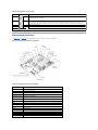
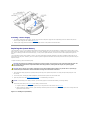
1
Dell™ PowerEdge™ 1750 Systems Installation and Troubleshooting Guide
Introduction
Indicators, Messages, and Codes
Finding Software Solutions
Running the System Diagnostics
Troubleshooting Your System
Installing System Options
Installing Drives
Getting Help
Jumpers and Connectors
I/O Connectors
Abbreviations and Acronyms
NOTE: A NOTE indicates important information that helps you make better use of your computer.
NOTICE: A NOTICE indicates either potential damage to hardware or loss of data and tells you how to avoid the problem.
CAUTION: A CAUTION indicates a potential for property damage, personal injury, or death.
Information in this document is subject to change without notice.
© 2002 Dell Computer Corporation. All rights reserved.
Reproduction in any manner whatsoever without the written permission of Dell Computer Corporation is strictly forbidden.
Trademarks used in this text: Dell, the DELL logo, PowerEdge, DellNet, Dell OpenManage, Dimension, Inspiron, Dell Precision, OptiPlex, and Latitude are trademarks of Dell Computer
Corporation; Xeon is a trademark and Intel is a registered trademark of Intel Corporation; Microsoft and Windows are registered trademarks of Microsoft Corporation.
Other trademarks and trade names may be used in this document to refer to either the entities claiming the marks and names or their products. Dell Computer Corporation
disclaims any proprietary interest in trademarks and trade names other than its own.
Initial release: 17 Dec 2002
Back to Contents Page
Jumpers and Connectors
Dell™ PowerEdge™ 1750 Systems Installation and Troubleshooting Guide
Jumpers—A General Explanation
System Board Jumpers
System Board Connectors
SCSI Backplane Board Connectors
Disabling a Forgotten Password
This section provides specific information about the jumpers on the system board. It also provides some basic information on jumpers and switches and
describes the connectors and sockets on the various boards in the system.
Jumpers—A General Explanation
Jumpers provide a convenient and reversible way of reconfiguring the circuitry on a printed circuit board. When reconfiguring the system, you may need to
change jumper settings on the system board. You may also need to change jumper settings on expansion cards or drives.
Jumpers
Jumpers are small blocks on a circuit board with two or more pins emerging from them. Plastic plugs containing a wire fit down over the pins. The wire
connects the pins and creates a circuit. To change a jumper setting, pull the plug off its pin(s) and carefully fit it down onto the pin(s) indicated. Figure A-1
shows an example of a jumper.
Figure A-1. Example Jumper
CAUTION: Make sure the system is turned off before you change a jumper setting. Otherwise, damage to the system or unpredictable results may
occur.
A jumper is referred to as open or unjumpered when the plug is pushed down over only one pin or if there is no plug at all. When the plug is pushed down
over two pins, the jumper is referred to as jumpered. The jumper setting is often shown in text as two numbers, such as 1-2. The number 1 is printed on the
circuit board so that you can identify each pin number based on the location of pin 1.
System Board Jumpers
Figure A-2 shows the location and default settings of the jumper blocks on the system board. See Table A-1 for the designations, default settings, and
functions of the system's jumpers.
Figure A-2. System Board Jumpers
Table A-1. System Board Jumper Settings Jumper
Setting
Description
PASSWD
(default) The password feature is enabled.
The password feature is disabled.
NVRAM_CLR
(default) The configuration settings are retained at system boot.
The configuration settings are cleared at next system boot. (If the configuration settings become corrupted to the point
where the system will not boot, install the jumper plug and boot the system. Remove the jumper before restoring the
configuration information.)
RSVD
jumpered Reserved (do not change).
unjumpered
System Board Connectors
See Figure A-3 and Table A-2 for the descriptions and locations of the system board connectors.
Figure A-3. System Board Connectors and Sockets
Table A-2. System Board Connectors and Sockets Connector or Socket Description
BACKPLANE
SCSI backplane board connector
B1
System battery connector
CYCLOPS
Cable-management arm system status connector
DIMM_1x; DIMM_2x
Memory module sockets
EMBEDDED_REMOTE_ Connector for optional RAC
ASSISTANT
EMP_NIC
RAC Ethernet port connector
ETHERNET_n
NIC connectors (2)
FANn
Cooling fan power connectors (six on system board; one on control panel assembly)
FRONT_PANEL
System control panel connector
KYBD
Keyboard connectors
MOUSE
Mouse connector
PCIn
PCI riser board connector
PROCESSOR 1
Microprocessor socket 1
PROCESSOR 2
Microprocessor socket 2
PS_PWR
System board power connector
PS_SIG
Power supply signal connector
RAID
Socket for optional ROMB card
RAID BAT
Backup battery connector for ROMB card
SCSI_B
External SCSI connector
SERIAL
Serial port connector
USBn
USB connector
VGA
VGA connector
SCSI Backplane Board Connectors
Figure A-4 shows the location of the connectors on the top of the SCSI backplane board.
Figure A-4. Connectors on the SCSI Backplane Board
Disabling a Forgotten Password
The system's software security features include a system password and a setup password, which are discussed in detail in "Using the System Setup
Program" in the User's Guide. A password jumper on the system board enables these password features or disables them and clears any password(s)
currently in use.
To disable a forgotten system password or setup password, perform the following steps.
CAUTION: Only trained service technicians are authorized to remove the system cover and access any of the components inside the system. See
your System Information Guide for complete information about safety precautions, working inside the computer, and protecting against
electrostatic discharge.
1.
Open the system covers. See "Opening the System Covers" in "Troubleshooting Your System."
2.
See Figure A-2 for the location of the password jumper (labeled "PASSWD") on the system board.
3.
Remove the jumper plug from the PASSWD jumper.
4.
Close the system covers. See "Closing the System Covers" in "Troubleshooting Your System."
5.
Reconnect the system to an electrical outlet and turn it on.
The existing passwords are not disabled (erased) until the system boots with the PASSWD jumper plug removed. However, before you assign a new
system and/or setup password, you must reinstall the jumper plug.
NOTE: If you assign a new system and/or setup password with the jumper plug still removed, the system disables the new password(s) the next
time it boots.
6.
Repeat step 1.
7.
Install the jumper plug on the PASSWD jumper.
8.
Close the system covers, and then reconnect the system and peripherals to their electrical outlets and turn them on.
9.
Assign a new system and/or setup password.
To assign a new passwords using the System Setup program, see "Assigning a System Password" in the User's Guide.
Back to Contents Page
Back to Contents Page
I/O Connectors
Dell™ PowerEdge™ 1750 Systems Installation and Troubleshooting Guide
I/O Connectors
Serial Connector
PS/2-Compatible Keyboard and Mouse Connectors
Video Connector
USB Connector
RAC Ethernet Connector
Integrated NIC Connector
Network Cable Requirements
I/O Connectors
I/O connectors are the gateways that the system uses to communicate with external devices, such as a keyboard, mouse, printer, or monitor. This section
describes the various connectors on your system. If you reconfigure the hardware connected to the system, you may also need the pin number and signal
information for these connectors. Figure B-1illustrates the I/O connectors on the system back panel; Figure B-2 identifies the I/O connectors on the front
panel.
Figure B-1. I/O Connectors on Back Panel
Figure B-2. I/O Connectors on Front Panel
Table B-1 shows the icons used to label the connectors on the system.
Table B-1. I/O Connector Icon Icon Connector
Serial connector
Mouse connector
Keyboard connector
Video connector
USB connector
NIC connector
RAC Ethernet connector
Serial Connector
Serial connectors support devices such as external modems, printers, and mice that require serial data transmission. The serial connector uses a 9-pin Dsubminiature connector.
Serial Connector Autoconfiguration
The default designation of the integrated serial connector is COM1. When you add an expansion card containing a serial connector that has the same
designation as the integrated connector, the system's autoconfiguration feature remaps (reassigns) the integrated serial connector to the next available
designation. Both the new and the remapped COM connectors share the same IRQ setting. COM1 and COM3 share IRQ4, while COM2 and COM4 share IRQ3.
NOTE: If two COM connectors share an IRQ setting, you may not be able to use them both at the same time. In addition, if you install one or more
expansion cards with serial connectors designated as COM1 and COM3, the integrated serial connector is disabled.
Before adding a card that remaps the COM connectors, check the documentation that came with the software to make sure that the software can
accommodate the new COM connector designation.
Figure B-3 illustrates the pin numbers for the serial connector and Table B-2 defines the pin assignments for the connector.
Figure B-3. Serial Connector Pin Numbers
Table B-2. Serial Connector Pin Assignments Pin
Signal I/O Definition
1
DCD
I
Data carrier detect
2
SIN
I
Serial input
3
SOUT
O
Serial output
4
DTR
O
Data terminal ready
5
GND
N/A
Signal ground
6
DSR
I
Data set ready
7
RTS
O
Request to send
8
CTS
I
Clear to send
9
RI
I
Ring indicator
N/A
Chassis ground
Shell N/A
PS/2-Compatible Keyboard and Mouse Connectors
The PS/2-compatible keyboard and mouse cables attach to 6-pin, miniature DIN connectors. Figure B-4 illustrates the pin numbers for these connectors and
Table B-3 defines the pin assignments for these connectors.
Figure B-4. PS/2-Compatible Keyboard and Mouse Connector Pin Numbers
Table B-3. Keyboard and Mouse Connector
Pin Assignments Pin
Signal
1
KBDATA or MSDATA I/O
I/O Definition
Keyboard data or mouse data
2
NC
N/A
No connection
3
GND
N/A
Signal ground
4
FVcc
N/A
Fused supply voltage
5
KBCLK or MSCLK
I/O
Keyboard clock or mouse clock
6
NC
N/A
No connection
N/A
Chassis ground
Shell N/A
Video Connector
You can attach a VGA-compatible monitor to the system's integrated video controller using a 15-pin high-density D-subminiature connector. Figure B-5
illustrates the pin numbers for the video connector and Table B-4 defines the pin assignments for the connector.
NOTE: Installing a video card automatically disables the system's integrated video controller.
Figure B-5. Video Connector Pin Numbers
Table B-4. Video Connector Pin Assignments Pin
Signal
I/O Definition
1
RED
O
Red video
2
GREEN
O
Green video
3
BLUE
O
Blue video
4
NC
N/A
No connection
5–8, 10 GND
N/A
Signal ground
9
VCC
N/A
Vcc
11
NC
N/A
No connection
12
DDC data out O
Monitor detect data
13
HSYNC
O
Horizontal synchronization
14
VSYNC
O
Vertical synchronization
15
DDC clock out O
Monitor detect clock
USB Connector
The system's USB connector supports USB-compliant peripherals such as keyboards, mice, and printers and may also support USB-compliant devices such as
diskette drives and CD drives. Figure B-6 illustrates the pin numbers for the USB connector and Table B-5 defines the pin assignments for the connector.
NOTICE: Do not attach a USB device or a combination of USB devices that draw a maximum current of more than 500 mA per channel or +5 V. Attaching
devices that exceed this threshold may cause the USB connectors to shut down. See the documentation that accompanied the USB devices for their
maximum current ratings.
Figure B-6. USB Connector Pin Numbers
Table B-5. USB Connector Pin Assignments Pin Signal I/O Definition
1
Vcc
2
DATA– I/O
N/A
Data (–)
3
DATA+ I/O
Data (+)
4
GND
Signal ground
N/A
Supply voltage
RAC Ethernet Connector
The system's optional RAC circuitry is designed to provide remote access capabilities for the system. It is designed specifically to work with systems
management software. Figure B-7 illustrates the pin numbers for the RAC Ethernet connector and Table B-6 defines the pin assignments for the connector.
Figure B-7. RAC Ethernet Connector
Table B-6. RAC Ethernet Connector Pin Assignments Pin Signal I/O Definition
1
TD+
O
Data out (+)
2
TD–
O
Data out (–)
3
RD+
I
Data in (+)
4
NC
N/A
No connection
5
NC
N/A
No connection
6
RD–
I
Data in (–)
7
NC
N/A
No connection
8
NC
N/A
No connection
Integrated NIC Connector
The system's integrated NIC functions as a separate network expansion card while providing fast communication between servers and workstations.
Figure B-8 illustrates the pin numbers for the NIC connector and Table B-7 defines the pin assignments for the connector.
Figure B-8. NIC Connector
Table B-7. NIC Connector Pin Assignments Pin Signal I/O Definition
1
TP0+
I/O
Data0 (+)
2
TP0–
I/O
Data0 (–)
3
TP1+
I/O
Data1 (+)
4
TP2+
I/O
Data2 (+)
5
TP2–
I/O
Data2 (–)
6
TP1–
I/O
Data1 (–)
7
TP3+
I/O
Data3 (+)
8
TP3–
I/O
Data3 (–)
Network Cable Requirements
The NIC supports a UTP Ethernet cable equipped with a standard RJ45-compatible plug. Observe the following cabling restrictions.
NOTICE: To avoid line interference, voice and data lines must be in separate sheaths.
l
Use Category 5 or greater wiring and connectors.
l
Do not exceed a cable run length (from a workstation to a hub) of 100 m (328 ft).
For detailed guidelines on operation of a network, see "Systems Considerations of Multi-Segment Networks" in the IEEE 802.3 standard.
Back to Contents Page
Back to Contents Page
Abbreviations and Acronyms
Dell™ PowerEdge™ 1750 Systems Installation and Troubleshooting Guide
The following list defines or identifies technical terms, abbreviations, and acronyms used in your user documents.
A
ampere(s)
AC
alternating current
ACPI
Advanced Configuration and Power Interface
ADC
analog-to-digital converter
ANSI
American National Standards Institute
APIC
Advanced Peripheral Interrupt Controller
ASIC
application-specific integrated circuit
BIOS
basic input/output system
bpi
bits per inch
bps
bits per second
BTU
British thermal unit
C
Celsius
CD
compact disc
CD
compact disc
CGA
color graphics adapter
cm
centimeter(s)
cpi
characters per inch
cpl
characters per line
CPU
central processing unit
DAC
digital-to-analog converter
DAT
digital audio tape
dB
decibel(s)
dBA
adjusted decibel(s)
DC
direct current
DDR
dual data rate
DIMM
dual in-line memory module
DIN
Deutsche Industrie Norm
DIP
dual in-line package
DMA
direct memory access
DOC
Department of Communications (in Canada)
dpi
dots per inch
DRAC
Dell remote access card
DRAM
dynamic random-access memory
DS/DD
double-sided double-density
DS/HD
double-sided high-density
DSA
Dell SCSI Array
ECC
error checking and correction
EDO
extended-data out
EGA
enhanced graphics adapter
EIDE
enhanced integrated drive electronics
EMI
electromagnetic interference
EMM
expanded memory manager
EMS
Expanded Memory Specification
EPP
Enhanced Parallel Port
EPROM
erasable programmable read-only memory
ESD
electrostatic discharge
ESDI
enhanced small-device interface
ESM
embedded server management
F
Fahrenheit
FAT
file allocation table
FCC
Federal Communications Commission
ft
feet
g
gram(s)
G
gravities
GB
gigabyte(s)
GUI
graphical user interface
h
Hz
hertz
I/O
input/output
ID
identification
IDE
integrated drive electronics
IRQ
interrupt request
K
kilo- (1024)
KB
kilobyte(s)
KB/sec
kilobyte(s) per second
Kb
kilobit(s)
Kbps
kilobit(s) per second
kg
kilogram(s)
kHz
kilohertz
LAN
local area network
lb
pound(s)
LCD
liquid crystal display
LED
light-emitting diode
LIF
low insertion force
LN
load number
lpi
lines per inch
LVD
low voltage differential
m
meter(s)
mA
milliampere(s)
mAh
milliampere-hour(s)
MB
megabyte(s)
Mb
megabit(s)
Mbps
megabit(s) per second
MBR
master boot record
MDA
monochrome display adapter
MGA
monochrome graphics adapter
MHz
megahertz
mm
millimeter(s)
ms
millisecond(s)
MTBF
mean time between failures
mV
millivolt(s)
NIC
network interface controller
NiCad
nickel cadmium
NiMH
nickel-metal hydride
NMI
nonmaskable interrupt
ns
nanosecond(s)
NTFS
NT File System
NVRAM
nonvolatile random-access memory
OTP
one-time programmable
PAL
programmable array logic
PCI
Peripheral Component Interconnect
PCMCIA
Personal Computer Memory Card International Association
PDB
power distribution board
PGA
pin grid array
POST
power-on self-test
ppm
pages per minute
PQFP
plastic quad flat pack
PS/2
Personal System/2
PXE
preboot execution environment
RAC
remote access controller
RAID
redundant arrays of independent disks
RAM
random-access memory
REN
ringer equivalence number
RFI
radio frequency interference
RGB
red/green/blue
ROM
read-only memory
ROMB
RAID on motherboard
rpm
revolutions per minute
RTC
real-time clock
SCSI
small computer system interface
sec
second(s)
SEC
single-edge contact
SDRAM
synchronous dynamic random-access memory
SIMM
single in-line memory module
SMB
server management bus
SNMP
Simple Network Management Protocol
SRAM
static random-access memory
SVGA
super video graphics array
TFT
thin film transistor
tpi
tracks per inch
UMB
upper memory block
UPS
uninterruptible power supply
USB
universal serial bus
V
volt(s)
VAC
volt(s) alternating current
VDC
volt(s) direct current
VGA
video graphics array
VLSI
very-large-scale integration
VRAM
video random-access memory
VRM
voltage regulator module
W
watt(s)
WH
watt-hour(s)
X
XMM
extended memory manager
XMS
eXtended Memory Specification
Z
ZIF
zero insertion force
Back to Contents Page
Back to Contents Page
Introduction
Dell™ PowerEdge™ 1750 Systems Installation and Troubleshooting Guide
Other Documents You May Need
Your system is a rack-dense, full-featured, highly available, rack-mount system equipped with one or two Intel® Xeon™ microprocessors. This system includes the following service features to make troubleshooting and repair easy and effective:
l
Systems management hardware, which monitors temperatures and voltages throughout the system and notifies you if the system overheats, if a
system cooling fan malfunctions, or if a power supply fails
l
A comprehensive system diagnostics program, which checks for hardware problems (if the system can boot)
The following system upgrade options are offered:
l
An additional Intel Xeon microprocessor
l
A second, hot-pluggable 320-W power supply
l
Additional memory up to 8 GB, by installing combinations of 128-MB, 256-MB, 512-MB, 1-GB, and 2-GB DDR SDRAM memory modules
l
Up to two additional 1-inch, internal U320 SCSI hard drives (for a total of three)
l
An optional ROMB through a separate RAID controller that incorporates 128 MB of cache memory and a RAID battery
l
Up to two PCI expansion cards: two 3.3-V, 64-bit, 133-MHz PCI-X cards or one 3.3-V, 64-bit, 133-MHz PCI-X card and one 5-V, 64-bit, 33-MHz PCI card
l
Optional remote access controller (RAC) card for remote systems management
Other Documents You May Need
The System Information Guide provides important safety and regulatory information. Warranty information may be included within this document or as a
separate document.
l
The Rack Installation Guide included with your rack solution describes how to install your system into a rack.
l
The Setting Up Your System document provides an overview of initially setting up your system.
l
The User's Guide provides information about system features and technical specifications
l
The Dell Remote Access Controller Installation and Setup Guide provides complete information about installing, configuring, and using a RAC to remotely
access a system.
l
Systems management software documentation describes the features, requirements, installation, and basic operation of the software.
l
Operating system documentation describes how to install (if necessary), configure, and use the operating system software.
l
Documentation for any components you purchased separately provides information to configure and install these options.
l
Updates are sometimes included with the system to describe changes to the system, software, and/or documentation.
NOTE: Always read the updates first because they often supersede information in other documents.
l
Release notes or readme files may be included to provide last-minute updates to the system or documentation or advanced technical reference material
intended for experienced users or technicians.
Back to Contents Page
Back to Contents Page
Indicators, Messages, and Codes
Dell™ PowerEdge™ 1750 Systems Installation and Troubleshooting Guide
Indicators on the Optional Bezel
Front-Panel Features
Back-Panel Features
Power Supply Features
System Messages
System Beep Codes
Warning Messages
Diagnostics Messages
Alert Messages
Applications, operating systems, and the system itself are capable of identifying problems and alerting you to them. When a problem occurs, a message may
appear on the monitor screen or a beep code may sound.
Several different types of messages can indicate when the system is not functioning properly:
l
Indicators on the front bezel
l
Front-panel indicators
l
SCSI hard drive indicators
l
Power supply indicators
l
System messages
l
System beep codes
l
Warning messages
l
Diagnostics messages
l
Alert messages
The system indicators and the front and back panel features are illustrated in the following figures. This section also describes each type of message and lists
the possible causes and actions you can take to resolve any problems indicated by a message. To determine what type of message you have received, read
the following sections.
Indicators on the Optional Bezel
The optional system bezel incorporates a system status indicator divided into blue and amber system status indicators. See Figure 2-1. The blue indicator
lights up when the system is operating correctly. The amber caution indicator lights up when the system needs attention due to a problem with power
supplies, fans, system temperature, system memory, or hard drives.
Table 2-1 lists the system's indicator patterns. Different patterns are displayed as events occur in the system.
Figure 2-1. System Status Indicators
Table 2-1. System Status Indicator Patterns Blue Indicator
Amber Caution Indicator
Description
Off
Off
Power is not available to the system, or power is available to the system, but the system is not powered
on.
Off
Blinking
The system has detected an error.
On
Off
Power is on, and the system is operational.
Blinking
Off
The indicator has been activated to identify the system in a rack.
NOTE: While the system is being identified, the blue indicator blinks even though an error has been detected. After the system is identified, the blue
indicator stops blinking and the amber indicator resumes blinking.
Front-Panel Features
Figure 2-2 shows the controls, indicators, and connectors located behind the optional bezel on the system's front panel. Table 2-2 provides a description of
each feature.
Figure 2-2. Front-Panel Features
Table 2-2. Front-Panel LED Indicators, Buttons,
and Connectors Indicator, Button,
or Connector
Icon
Description
Blue system status
indicator
The blue system status indicator lights up during normal system operation. Both the systems management software and
the identification buttons located on the front and back of the system can cause the blue system status indicator to flash
to identify a particular system.
Amber system status
indicator
The amber system status indicator flashes when the system needs attention. Check for a problem with the power
supplies, fans, system temperature, or hard drives.
NOTE: If the system is connected to AC power and an error has been detected, the amber system status indicator flashes
regardless of whether the system has been powered on.
NIC1 and NIC2 link
and activity indicators
The link and activity indicators for the two integrated NICs light intermittently when the NICs are in use.
Hard-drive activity
indicator
The green hard-drive activity indicator flashes when the hard drives are in use. See Figure 2-3 for more information on
hard-drive indicators.
Power-on indicator,
power button
The power-on indicator lights when the system power is on.
The power button controls the DC power supply output to the system.
NOTE: If you turn off the system using the power button and the system is running an ACPI-compliant operating system,
the system performs a graceful shutdown before the power is turned off. If the system is not running an ACPI-compliant
operating system, the power is turned off immediately after the power button is pressed.
Identification button
The identification buttons on the front and back panels can be used to locate a particular system within a rack. When one
of these buttons is pushed, the blue system status indicator on the front and back blinks until one of the buttons is
pushed again.
USB connector
Connects a USB 1.1-compliant device to the system.
Video connector
Connects a monitor to the system.
SCSI Hard-Drive Indicator Codes
If the optional ROMB card is activated, two indicators on each of the hard-drive carriers provide information about the status of the hard drives. See Figure 2-3
and Table 2-3. The SCSI backplane firmware controls the drive power-on/fault indicator.
Figure 2-3. SCSI Hard-Drive Indicators
Table 2-3 lists the drive indicator patterns. Different patterns are displayed as drive events occur in the system. For example, if a hard drive fails, the "drive
failed" pattern appears. After the drive is selected for removal, the "drive being prepared for removal" pattern appears, followed by the "drive ready for
insertion or removal" pattern. After the replacement drive is installed, the "drive being prepared for operation" pattern appears, followed by the "drive online"
pattern.
NOTE: If the optional ROMB card is not installed, only the "drive online" indicator pattern appears. The drive-activity indicator also blinks when the drive
is being accessed.
Table 2-3. SCSI Hard-Drive Indicator Patterns Condition
Indicator Pattern
Identify drive
The green power-on/fault indicator blinks four times per second.
Drive being prepared for removal
The green power-on/fault indicator blinks two times per second.
Drive ready for insertion or removal Both drive indicators are off.
Drive being prepared for operation
The green power-on/fault indicator is on.
Drive predicted failure
The power-on/fault indicator slowly blinks green, amber, and off.
Drive failed
The amber power-on/fault indicator blinks four times per second.
Drive rebuilding
The green power-on/fault indicator blinks slowly.
Drive online
The green power-on/fault indicator is on.
Back-Panel Features
Figure 2-4 shows the controls, indicators, connectors, and expansion slots located on the system's back panel.
l
For information about the connectors, see "System Board Connectors" in "Jumpers and Connectors."
l
The blue and amber system status indicator combines the functions of the separate blue and amber system status indicators on the front panel. For
more information, see Table 2-2.
l
For information about the identification buttons located on the front and back of the system, see "Front-Panel Features."
l
For PCI card information, see "Installing Expansion Cards" in "Installing System Options."
NOTE: Connect the power cable to connector PS1 if your system only has one power supply. See Figure 2-4.
Figure 2-4. Back-Panel Features and Indicators
Power Supply Features
Each hot-pluggable power supply has three indicators, visible when the system covers are open, that indicate whether power is present or whether a power
fault has occurred. See Table 2-4 for more information about the indicators. See "Opening the System Covers" in "Troubleshooting Your System" for
information about accessing the inside of the system.
Figure 2-5. Power Supply Features
Table 2-4. Power-Supply Indicator Patterns Indicator
Indicator Code
Line status
Green indicates that a valid power source is connected to the system.
Power-supply fault
Red indicates a problem with the power supply.
Power-supply status Green indicates that the power supply is operational.
System Messages
System messages alert you to a possible operating system problem or to a conflict between the software and hardware. Table 2-5 lists the system error
messages that can occur and the probable cause for each message.
NOTE: If you receive a system message that is not listed in Table 2-5, check the documentation for the application that is running when the message
appears or the operating system's documentation for an explanation of the message and recommended action.
Table 2-5. System Messages Message
Causes
Corrective Actions
Address mark not found
Faulty diskette/CD drive subsystem or
hard-drive subsystem (defective system
board).
See "Getting Help."
Amount of available memory limited to 256 MB! OS Install Mode is enabled in the
System Setup program.
Disable the OS Install Mode in the System Setup program.
See "Using the System Setup program" in the User's Guide.
Alert! One or more of the memory DIMMs are
out of rev.
One or more of the installed DIMMs are
Ensure that all installed memory meets the system
not supported by the system. DIMMs
specifications. See "Installing Memory Modules" in "Installing
must be registered DDR SDRAM rated for System Options."
266-MHz operation.
Alert! Redundant memory disabled! Memory
configuration does not support redundant
memory.
One memory bank is not populated, or
memory banks are different sizes. To
support redundant memory, both banks
must be populated, and all four DIMMs
must be the same size.
Alert! Unsupported memory, incomplete sets,
or unmatched sets.
DIMMs are installed in a mismatched
Ensure that memory is installed in matched pairs. See
pair, or one memory slot in a bank is
"Installing Memory Modules" in "Installing System Options."
empty. Memory must be installed in
matched pairs. In a mismatched memory
bank, neither DIMM is used.
The following memory DIMM(s) have been
disabled: DIMM_xx
Install identical DIMMs in all four memory banks. See
"Installing Memory Modules" in "Installing System Options."
Auxiliary device failure
Mouse or keyboard cable connector
Check the mouse and keyboard cable connections. See
loose or improperly connected; defective "Troubleshooting External Connections" in "Troubleshooting
mouse or keyboard.
Your System." If the problem persists, replace the mouse. If
the problem persists, replace the keyboard. See "Getting
Help."
Attachment failed to respond.
Diskette drive or hard-drive controller
cannot send data to associated drive.
Reboot the system. If you receive an error message from the
SCSI, RAID, or diskette controller, see "Getting Help."
If no error message appears at system boot, reseat all
drives. If the problem persists, see "Getting Help."
Bad error-correction code (ECC) on disk read. Faulty diskette drive, tape drive, or
hard-drive subsystem (defective
Controller has failed.
backplane board).
Reseat all drives and reboot the system. If the error message
reappears, see "Getting Help."
BIOS Update Attempt Failed!
Remote BIOS update attempt failed.
Retry the BIOS update. If the problem persists, see "Getting
Help."
Caution! NVRAM_CLR jumper is installed on
system board - please run SETUP program.
Incorrect configuration settings in
System Setup program, NVRAM_CLR
jumper is installed, or faulty system
battery.
Check the System Setup configuration settings. See "Using
the System Setup Program" in the User's Guide. Remove the
NVRAM_CLR jumper. See Figure A-2 for jumper location.
Replace the battery. See "Replacing the System Battery" in
"Installing System Options."
CPUs with different cache sizes detected.
Two different types of microprocessors
are installed.
Install a correct version of the microprocessor so that both
microprocessors have the same level 2 cache size. See
"Installing Microprocessors" in "Installing System Options."
Data error
Faulty diskette, diskette drive, or hard
drive.
Replace the diskette. Reseat all drives and reboot the
system. If the error message reappears, see "Getting Help."
Decreasing available memory
One or more memory modules
improperly seated or faulty.
Remove and reseat the memory modules. See "Installing
Memory Modules" in "Installing System Options." If the
problem persists, replace the memory modules. If the problem
persists, see "Getting Help."
Diskette drive 0 seek failure
Faulty or improperly inserted diskette or
incorrect configuration settings in
System Setup program.
Reseat the diskette drive and replace the diskette. See
"Installing a Diskette Drive" in "Installing Drives." Run the
System Setup program to correct the diskette drive type. See
"Using the System Setup Program" in the User's Guide.
Diskette read failure
Faulty diskette, or faulty or improperly
connected diskette drive.
Reseat the diskette drive and replace the diskette. See
"Installing a Diskette Drive" in "Installing Drives."
Diskette subsystem reset failed
Faulty diskette/CD drive controller
(defective system board).
Replace the system board. See "Getting Help."
Diskette write protected
Diskette write-protect feature is
enabled.
Disable the write-protect feature on the diskette.
Drive not ready
Diskette missing from or improperly
inserted into the diskette drive.
Reinsert the diskette into the drive.
ECC memory error
Improperly seated or faulty memory
modules.
Remove and reseat the memory modules. See "Installing
Memory Modules" in "Installing System Options." If the
problem persists, replace the memory modules. If the problem
persists, see "Getting Help."
Embedded server management error
Embedded server management memory
may be temporarily corrupted.
To clear the embedded server management memory, shut
down the system, disconnect the power cord(s), wait
approximately 30 seconds, and then reconnect the power
cord(s) and restart the system. If the problem persists, see
"Getting Help."
Defective RAC or system board.
Replace the RAC. See the documentation that came with the
Diskette drive 1 seek failure
Embedded server management is not present
Error: Dell Remote Access Controller
RAC. If the problem persists, you may need to replace the
system board. See "Getting Help."
initialization failure
Gate A20 failure
Faulty keyboard controller (defective
system board).
General failure
Application program or operating system Reboot. If the message reappears, see your software
failure.
documentation.
Hard disk controller failure
Incorrect configuration settings in the
System Setup program, improperly
connected hard drive, or faulty harddrive controller subsystem (defective
system board).
Check the hard-drive configuration settings in the System
Setup program. See "Using the System Setup Program" in the
User's Guide. Reinstall the hard drive. See "Installing SCSI
Hard Drives" in "Installing Drives."
Invalid configuration information - please
run SETUP program.
Incorrect configuration settings in the
System Setup program, the NVRAM_CLR
jumper is installed, or the system
battery is faulty.
Check the System Setup configuration settings. See "Using
the System Setup Program" in the User's Guide. Remove the
NVRAM_CLR jumper. See Figure A-2 for jumper location.
Replace the battery. See "Replacing the System Battery" in
"Installing System Options."
Invalid memory configuration detected.
Potential for data corruption exists!
Memory modules are not installed in
matched pairs.
Install memory modules in matched pairs. See "Installing
Memory Modules" in "Installing System Options."
Invalid NVRAM configuration, resource reallocated
System configuration data has been
ignored.
Check the System Setup configuration settings. See "Using
the System Setup Program" in the User's Guide.
I/O card parity interrupt at address
Expansion card(s) is improperly installed
or faulty.
Reinstall the expansion card(s). See "Installing Expansion
Cards" in "Installing System Options." If the problem persists,
replace the expansion card(s).
Keyboard controller failure
Defective keyboard/mouse controller
(defective system board).
Replace the system board. See "Getting Help."
Keyboard data line failure
Keyboard cable connector is loose or
improperly connected; defective
keyboard; defective keyboard/mouse
controller (defective system board).
Check the keyboard cable connection. Replace the keyboard.
If the problem persists, replace the system board. See
"Getting Help."
Memory allocation error
Memory module(s) is not connected
properly, or an application program or
the operating system failed.
Reseat the modules. See "Installing Memory Modules" in
"Installing System Options." Reboot the system. If the
message reappears, see your software documentation.
Memory address line failure at address, read
value expecting value
Faulty or improperly seated memory
modules or defective system board.
Memory high data line failure at start
address to end address
Remove and reseat the memory modules. See "Installing
Memory Modules" in "Installing System Options." If the
problem persists, replace the memory modules. If the problem
persists, see "Getting Help."
Hard disk read failure
Keyboard stuck key failure
Replace the system board. See "Getting Help."
Keyboard clock line failure
Keyboard failure
Memory high address line failure at start
address to end address
Memory double word logic failure at start
address to end address
Memory double word logic failure at address,
read value expecting value
Memory odd/even logic failure at start
address to end address
Memory odd/even logic failure at address,
read value expecting value
Memory write/read failure at address, read
value expecting value
Memory write/read failure at start address to
end address
Memory parity failure at start address to end Improperly seated or faulty memory
modules.
address
Memory parity error at address
Remove and reseat the memory modules. See "Installing
Memory Modules" in "Installing System Options." If the
problem persists, replace the memory modules. If the problem
persists, see "Getting Help."
No boot device available
Faulty diskette, diskette/CD drive
subsystem, hard drive, or hard-drive
subsystem; no boot disk in drive A.
Replace the diskette or the hard drive. See "Installing Drives."
If the problem persists, replace the system board. See
"Getting Help."
No boot sector on hard- disk
No operating system on the hard drive.
Check the hard-drive configuration settings in the System
Setup program. See "Using the System Setup Program" in the
User's Guide.
No timer tick interrupt
Defective system board.
Replace the system board. See "Getting Help."
No PXE-capable device available
<F12> was pressed during POST and no Check the cables connected to the NICs. Check the
PXE devices are detected.
configuration settings in the System Setup program for the
NICs. See "Using the System Setup Program" in the User's
Guide.
Non-system disk or disk error
Faulty diskette, diskette drive
subsystem, or hard-drive subsystem.
Replace the diskette. Reseat all drives and reboot the
system. If the error message reappears, see "Getting Help."
Not a boot diskette
No operating system on diskette.
Use a bootable diskette.
PCI BIOS failed to install
PCI device (option ROM) checksum
failure is detected during shadowing.
Contact the PCI device manufacturer to obtain a suitable
replacement PCI option ROM. Follow the manufacturer's
instructions to install the option ROM.
Plug & Play Configuration Error
Error encountered when initializing the
PCI device, or the system board is
defective.
Install the NVRAM_CLR jumper and reboot the system. If the
problem persists, replace the system board. See "Getting
Help."
Plug & Play Configuration Error PCI_n
Error encountered when initializing the
PCI adapter.
Install the NVRAM_CLR jumper and reboot the system. If the
problem persists, replace the specified expansion-card. See
"Installing Expansion Cards" in "Installing System Options." If
the problem persists, replace the system board. See "Getting
Help."
Primary backplane error
Improperly attached or missing
backplane.
Ensure that the SCSI backplane board is fully seated. See
"Troubleshooting SCSI Hard Drives" in "Troubleshooting Your
System."
Primary IDE device 0 not found
Improperly connected or missing IDE
device.
Ensure that the device's interface cable is securely connected
to the SCSI backplane board. Replace the device. If the
problem persists, see "Getting Help."
Defective microprocessor or system
board (reported by the NMI handler).
Replace the specified microprocessor. See "Installing
Microprocessors" in "Installing System Options." If the
problem persists, replace the system board. See "Getting
Help."
Primary IDE device 1 not found
Processor 1 internal error
Processor 2 internal error
Processor bus error
Defective system board (reported by the Replace the system board. See "Getting Help."
NMI handler).
PCI bus error
IMB bus error
Processor x is not a 533-MHz system bus
processor
This system supports only Intel® Xeon™ 533-MHz front-side-bus (system
bus) processors.
This system bus speed is not supported on
this system board.
Reboot the system. If you receive beep code 4-4-3 (processor
frequency mismatch), replace processor x with a supported
processor. See "Installing Microprocessors" in "Installing
System Options."
If a beep code does not occur at system boot, turn off the
system, install the NVRAM_CLR jumper, and reboot the
system. If the message reappears, see "Getting Help."
Faulty diskette, diskette-drive
subsystem, or hard-drive subsystem.
Replace the diskette, or reseat all drives and reboot the
system. If the message reappears, see "Getting Help."
Reset failed
Improperly connected diskette/tape
drive, hard drive, or power cable.
Check the drive and cable connections, and reset the system
again. If the message reappears, see "Getting Help."
ROM bad checksum = address
Expansion card improperly installed or
faulty.
Reinstall the expansion card. See "Installing Expansion
Cards" in "Installing System Options."
Sector not found
Defective sectors on diskette or hard
drive.
Replace the diskette, or reseat all drives and reboot the
system. If the message reappears, see "Getting Help."
Read fault
Requested sector not found
Seek error
Seek operation failed
Faulty diskette, diskette-drive
subsystem, or hard-drive subsystem.
Shutdown failure
Defective system board.
Replace the system board. See "Getting Help."
System backplane error
Improperly attached or missing SCSI
backplane.
Check that the SCSI backplane board is fully seated. See
"Troubleshooting SCSI Hard Drives" in "Troubleshooting Your
System."
System halted! Must power down.
Wrong password entered too many
times.
Reboot the system and enter the correct password. If the
problem persists, see "Disabling a Forgotten Password" in
"Jumpers and Connectors."
System parity error
Defective expansion card(s) or
improperly seated or faulty memory
modules (reported by the NMI handler).
Replace the expansion cards one at a time until the error is
corrected. See "Installing Expansion Cards" in "Installing
System Options."
Remove and reseat the memory modules. See "Installing
Memory Modules" in "Installing System Options." If the
problem persists, replace the memory modules. If the problem
persists, see "Getting Help."
One or more of the installed DIMMs has
a frequency less than 266 MHz. System
memory must be rated for 266 MHz. Replace lower-speed DIMM(s) with modules rated for 266MHz operation. See "Installing Memory Modules" in "Installing
System Options."
Time-of-day clock stopped
Defective battery or faulty chip
(defective system board).
Replace the system battery. See "Replacing the System
Battery" in "Installing System Options." If the problem
persists, replace the system board. See "Getting Help."
Time-of-day not set - please run SETUP
program
Incorrect Time or Date settings or
defective system battery.
Check the Time and Date settings. See "Using the System
Setup Program" in the User's Guide. If the problem persists,
replace the system battery. See "Replacing the System
Battery" in "Installing System Options." If the problem
persists, replace the system board. See "Getting Help."
Timer chip counter 2 failed
Defective system board.
Replace the system board. See "Getting Help."
Unsupported CPU combination
Microprocessor combination is not
supported by the system.
Install a supported microprocessor combination. See
"Installing Microprocessors" in "Installing System Options."
Unsupported CPU stepping detected.
Microprocessor is not supported by the
system.
Install the correct version of the microprocessor in the
specified microprocessor socket. See "Installing
Microprocessors" in "Installing System Options."
Utility partition not available
<F10> key was pressed during POST,
Create a utility partition on the boot hard drive. See "Using
The following memory DIMMs are unsupported:
DIMM_xx.
This system only supports 266 MHz DIMMs.
but no utility partition exists on the boot the Dell OpenManage Server Assistant CD" in your User's
hard drive.
Guide.
Warning: Detected mode change from SCSI to
RAID on channel x of the embedded RAID
subsystem.
Type of controller has changed since
previous system boot.
Back up information on the hard drives before changing the
type of controller used with the drives.
Type of controller has changed since
previous system boot.
Back up information on the hard drives before changing the
type of controller used with the drives.
Warning: Detected missing RAID hardware for
the embedded RAID subsystem. Data loss will
occur! Press Y to switch mode to SCSI, press
any other key to disable both channels. Press
Y to confirm the change; press any other key
to cancel.
Warning: Detected mode change from RAID to
SCSI on channel x of the embedded RAID
subsystem.
Warning: Detected missing RAID hardware for
the embedded RAID subsystem. Data loss will
occur! Press Y to switch mode to SCSI, press
any other key to disable both channels. Press
Y to confirm the change; press any other key
to cancel.
Warning! Embedded SCSI- RAID error
Faulty RAID adapter, or ROMB card
firmware is either corrupted or is the
wrong version.
Reseat the ROMB card. See "Installing a ROMB Card" in
"Installing System Options." Reboot the system. If the
message reappears, see "Getting Help."
Warning! Embedded SCSI- RAID firmware is not
present!
ROMB card firmware is either corrupted
or is the wrong version.
Reseat the ROMB card. See "Installing a ROMB Card" in
"Installing System Options." Reboot the system. If the
message reappears, see "Getting Help."
Warning! Firmware is out- of-date, please
update
Out-of-date firmware.
Update the system firmware. See "Using the Dell OpenManage
Server Assistant CD" in your User's Guide for information about
updating the system firmware.
Warning! No microcode update loaded for
processor x
BIOS is not current.
Update the BIOS, but do not turn the system off before the
update. See "Using the System Setup Program" in the User's
Guide.
Warning! Remote Access Controller command
failure
Command protocol failure between the
RAC and ESM3.
Reseat the RAC in its system board connector. See "Removing
and Replacing the Optional Front Bezel" (if necessary) and
"Opening the System Covers" in "Troubleshooting Your
System." See Figure A-3 in "Jumpers and Connectors" for the
location of the RAC Ethernet connector. If the message
reappears, see "Getting Help."
Warning! Unsupported Remote Access Controller RAC firmware is corrupted or is the
wrong version.
firmware version detected
Write fault
Faulty diskette or hard drive.
Reseat the RAC in its system board connector. See "Removing
and Replacing the Optional Front Bezel" (if necessary) and
"Opening the System Covers" in "Troubleshooting Your
System." See Figure A-3 in "Jumpers and Connectors" for the
location of the RAC connector. If the message reappears, see
"Getting Help."
Replace the diskette or hard drive. See "Installing Drives."
Write fault on selected drive
System Beep Codes
When an error that cannot be reported on the monitor occurs during a boot routine, the system may emit a series of beeps that identify the problem.
NOTE: If the system boots without a keyboard, mouse, or monitor attached, the system will not issue beep codes related to these peripherals.
When a beep code is emitted, record it on a copy of the Diagnostics Checklist in "Getting Help," and then look it up in Table 2-6. If you are unable to resolve
the problem by looking up the meaning of the beep code, use the system diagnostics to identify a more serious cause. If you are still unable to resolve the
problem, see "Getting Help."
Table 2-6. System Beep Codes Code
Cause
Corrective Action
1-1-2
Microprocessor register test failure
Replace microprocessor 1. See "Installing Microprocessors" in "Installing System Options." If the
problem persists, replace microprocessor 2.
1-1-3
CMOS write/read failure
Replace the system board. See "Getting Help."
1-1-4
BIOS checksum failure
This fatal error usually requires replacement of the BIOS firmware. See "Getting Help."
1-2-1
Programmable interval-timer failure
Replace the system board. See "Getting Help."
1-2-2
1-2-3
DMA initialization failure
DMA page register write/read failure
1-3-1
Main-memory refresh verification failure
Remove and reseat the memory modules. See "Installing Memory Modules" in "Installing System
Options." If the problem persists, replace the memory modules. If the problem persists, see
"Getting Help."
1-3-2
No memory installed
1-3-3
Chip or data line failure in the first 64 KB of main memory
1-3-4
Odd/even logic failure in the first 64 KB of main memory
1-4-1
Address line failure in the first 64 KB of main memory
1-4-2
Parity failure in the first 64 KB of main memory
2-1-1
through
2-4-4
Bit failure in the first 64 KB of main memory
3-1-1 Slave DMA-register failure
3-1-2
Master DMA-register failure
3-1-3
Master interrupt-mask register failure
3-1-4
Slave interrupt-mask register failure
3-2-4
Keyboard-controller test failure
Check the keyboard cable and connector for proper connection. If the problem persists, replace
the keyboard. If the problem persists, replace the system board. See "Getting Help."
3-3-1
CMOS failure
Replace the system board. See "Getting Help."
3-3-2
System configuration check failure
3-3-3
Keyboard controller not detected
3-3-4 Screen initialization failure
3-4-2
Screen-retrace test failure
3-4-3
Search for video ROM failure
4-2-1
No timer tick
4-2-2
Shutdown failure
4-2-3
Gate A20 failure
4-2-4
Unexpected interrupt in protected mode
Ensure that all expansion cards are properly seated, and then reboot the system.
4-3-1
Improperly seated or faulty memory modules
Remove and reseat the memory modules. See "Installing Memory Modules" in "Installing System
Options." If the problem persists, replace the memory modules. If the problem persists, see
"Getting Help."
4-3-3
Defective system board
Replace the system board. See "Getting Help."
4-3-4
Time-of-day clock stopped
Replace the battery. See "Replacing the System Battery" in "Installing System Options." If the
problem persists, replace the system board. See "Getting Help."
4-4-1
Super I/O chip failure (defective system board)
Replace the system board. See "Getting Help."
4-4-3
Microprocessor frequency mismatch. Occurs
when the front-side (external) bus speed of a
microprocessor is not 533 MHz.
If video is available, a screen message identifies the faulty microprocessor. Replace the
microprocessor. If video is not available, replace microprocessor 1 and then, if the problem
persists, replace microprocessor 2. See "Installing Microprocessors" in "Installing System
Options."
4-4-4
Cache test failure (defective microprocessor)
Remove and reseat the specified microprocessor. See "Installing Microprocessors" in "Installing
System Options." If the problem persists, replace the microprocessor. If the problem persists,
see "Getting Help."
Replace the system board. See "Getting Help."
Warning Messages
A warning message alerts you to a possible problem and asks you to take corrective action before the system continues a task. For example, before you
format a diskette, a message may warn you that you may lose all data on the diskette, as a way to protect against inadvertently erasing or writing over the
data. These warning messages usually interrupt the procedure and require you to respond by typing y (yes) or n (no).
NOTE: Warning messages are generated by either the application program or the operating system. See "Finding Software Solutions" and the
documentation that accompanied the operating system or application program for more information on warning messages.
Diagnostics Messages
When you run a test group or subtest in the system diagnostics, an error message may result. These particular error messages are not covered in this
section. Record the message on a copy of the Diagnostics Checklist (see "Getting Help"), and then follow the instructions in that section for obtaining technical
assistance.
Alert Messages
The optional system management software generates alert messages for your system. For example, the server agent software generates messages that
appear in the SNMP trap log file. Alert messages consist of information, status, warning, and failure messages for drive, temperature, fan, and power
conditions. More information about alert messages is provided in the system management software documentation found on the documentation CD that
shipped with your system.
Back to Contents Page
Back to Contents Page
Finding Software Solutions
Dell™ PowerEdge™ 1750 Systems Installation and Troubleshooting Guide
Before You Begin
Troubleshooting Errors and Conflicts
Software problems can be caused by:
l
Improper installation or configuration of an application
l
Application conflicts
l
Input errors
l
Interrupt assignment conflicts
Ensure that you are installing the software application according to the software manufacturer's recommended procedures. If a problem occurs after you
install the software, you might need to troubleshoot your software application and your system.
See the documentation that accompanied the software or contact the software manufacturer for detailed troubleshooting information.
NOTE: If all of the system diagnostic tests complete successfully, then the problem is most likely caused by the software and not the hardware.
Before You Begin
l
Scan the software media with antivirus software.
l
Read the software documentation before you run the installation utility.
l
Be prepared to respond to prompts from the installation utility.
The installation utility may require you to enter information about your system, such as how the operating system is configured, and the type of
peripherals that are connected to the system. Have this information available before running the installation utility.
Troubleshooting Errors and Conflicts
While configuring and running software, problems might occur that are caused by input errors, application conflicts, and/or IRQ assignment conflicts. The
problems are sometimes indicated by error messages.
Error messages are generated by system hardware or software. "Indicators, Messages, and Codes" provides information about error messages that are
hardware-based. If you receive an error message that is not listed, see your operating system or software program documentation for troubleshooting
information.
Input Errors
Pressing a specific key or set of keys at the wrong time may produce unexpected results. See the documentation that came with the software application to
ensure that the values or characters you are entering are valid.
Ensure that your operating system is configured properly to run the application. Remember that whenever you change the parameters of the operating
system, the changes can conflict with an application's operating requirements. After you configure the operating system, you may need to reinstall or
reconfigure a software application so that it can run properly in its new environment.
Application Conflicts
Some applications can leave unnecessary files or data behind after they are deleted from your system. Device drivers can also create application errors. If
application errors occur, see your application device driver or operating system documentation for troubleshooting information.
IRQ Assignment Conflicts
Most PCI devices can share an IRQ with another device, but they cannot use an IRQ simultaneously. To avoid this type of conflict, see the documentation for
each PCI device for specific IRQ requirements.
Table 3-1. IRQ Assignments IRQ Line Assignment
IRQ0
System timer
IRQ1
Keyboard controller
IRQ2
Interrupt controller 1 to enable IRQ8 through IRQ15
IRQ3
Reserved for system use
IRQ4
Serial port 1 (COM1 and COM3)
IRQ5
Available
IRQ6
Diskette drive controller
IRQ7
Available
IRQ8
Real-time clock/system CMOS
IRQ9
ACPI functions (used for power management)
IRQ10
Used by ESM hardware
IRQ11
Available
IRQ12
PS/2 mouse port unless the mouse is disabled through the System Setup program
IRQ13
Math coprocessor
IRQ14
RAC, if installed; available if a RAC is not installed
IRQ15
Secondary IDE controller
Back to Contents Page
Back to Contents Page
Running the System Diagnostics
Dell™ PowerEdge™ 1750 Systems Installation and Troubleshooting Guide
Using Server Administrator Diagnostics
System Diagnostics Features
When to Use the System Diagnostics
Running the System Diagnostics
System Diagnostics Testing Options
Using the Advanced Testing Options
Error Messages
If you experience a problem with your system, run the diagnostics before calling for technical assistance. The purpose of the diagnostics is to test your
system's hardware without requiring additional equipment or risking data loss. If you are unable to fix the problem yourself, service and support personnel can
use diagnostics test results to help you solve the problem.
Using Server Administrator Diagnostics
To assess a system problem, first use the online Server Administrator diagnostics. If you are unable to identify the problem, then use the system diagnostics.
To access the online diagnostics, log into the Server Administrator home page, and then click the Diagnostics tab. For information about using diagnostics,
see the online help. For additional information, see the Server Administrator User's Guide.
System Diagnostics Features
The system diagnostics provides a series of menus and options for particular device groups or devices. The system diagnostics menus and options allow you
to:
l
Run tests individually or collectively.
l
Control the sequence of tests.
l
Repeat tests.
l
Display, print, or save test results.
l
Temporarily suspend testing if an error is detected or terminate testing when a user-defined error limit is reached.
l
View help messages that briefly describe each test and its parameters.
l
View status messages that inform you if tests are completed successfully.
l
View error messages that inform you of problems encountered during testing.
When to Use the System Diagnostics
If a major component or device in the system does not operate properly, component failure may be indicated. As long as the microprocessor and the system's
input/output devices (monitor, keyboard, and diskette drive) are functioning, you can use the system diagnostics to help identify the problem.
Running the System Diagnostics
The system diagnostics can be run either from the utility partition on your hard drive or from a set of diskettes that you create using the Dell OpenManage
Server Assistant CD.
NOTICE: Use the system diagnostics to test only your system. Using this program with other systems may cause invalid results or error messages. In
addition, use only the program that came with your system (or an updated version of that program).
From the Utility Partition
1.
As the system boots, press <F10> during POST.
2.
From the utility partition main menu under Run System Utilities, select Run System Diagnostics.
From the Diagnostics Diskettes
1.
Create a set of diagnostics diskettes from the Dell OpenManage Server Assistant CD. See "Using the Dell OpenManage Server Assistant CD" in your
User's Guide for information on creating the diskettes.
2.
Insert the first diagnostics diskette.
3.
Reboot the system.
If the system fails to boot, see "Getting Help."
When you start the system diagnostics, a message is displayed stating that the diagnostics are initializing. Next, the Diagnostics menu appears. The menu
allows you to run all or specific diagnostics tests or to exit the system diagnostics.
NOTE: Before you read the rest of this section, start the system diagnostics so that you can see the utility on your screen.
System Diagnostics Testing Options
To select an option from the Diagnostics menu, highlight the option and press <Enter>, or press the key that corresponds to the highlighted letter in the
option.
Table 4-1 provides a brief explanation of testing options.
Table 4-1. System Diagnostics Testing Options Testing Option
Function
Quick Tests
Performs a quick check of the system. Select Test All Devices and then select Quick Tests. This option runs device tests that do not
require user interaction. Use this option to quickly identify the source of your problem.
Test One Device
Tests a particular device.
Extended Tests
Performs a more thorough check of the system. Select Test All Devices and then select Extended Tests.
Advanced Testing
Checks a particular area of the system.
Information and
Results
Displays test results.
Program Options
Sets various test parameters.
Device
Configuration
Displays an overview of the devices in the system.
Exit to MS-DOS
Exits the diagnostics and returns to the System Utilities menu.
Using the Advanced Testing Options
When you select Advanced Testing from the Diagnostics menu, the main screen of the diagnostics appears and displays the following information:
l
Two lines at the top of the screen identify the diagnostics utility, the version number, and the system's service tag number.
l
The left side of the screen under Device Groups lists the diagnostic device groups in the order that they are tested if you select All under the Run
Tests submenu. Press the up- or down-arrow keys to highlight a particular device group. Press the left- or right-arrow keys to select the options on the
menu. As you move from one menu option to another, a brief explanation of the highlighted option appears at the bottom of the screen.
l
The right side of the screen under Devices for Highlighted Group lists the specific devices within a particular test group.
l
The menu area consists of two lines at the bottom of the screen. The first line lists the menu options that you can select; press the left- or right-arrow
key to highlight an option. The second line provides information about the highlighted option.
For more information about a device group or device, highlight the Help option and press <Enter>. Press <Esc> to return to the previous screen.
Error Messages
When you run a system diagnostics test, you may receive an error message during testing. Record the message on a copy of the Diagnostics Checklist. For a
copy of the Diagnostics Checklist and instructions for obtaining technical assistance, see "Getting Help."
Back to Contents Page
Back to Contents Page
Troubleshooting
Your System
Dell™ PowerEdge™ 1750 Systems Installation and Troubleshooting Guide
Safety First—For You and Your System
Troubleshooting the System Battery
Checking the Equipment
Troubleshooting Power Supplies
Start-Up Routine
Troubleshooting System Cooling Problems
Troubleshooting External Connections
Troubleshooting System Memory
Responding to a Systems Management Software Alert
Message
Inside the System
Removing and Replacing the Optional Front Bezel
Opening the System Covers
Troubleshooting a Diskette Drive
Troubleshooting a CD Drive
Troubleshooting SCSI Hard Drives
Troubleshooting an Optional Integrated RAID Controller
(ROMB Card)
Closing the System Covers
Troubleshooting a RAID Controller Card
Troubleshooting a Wet System
Troubleshooting Expansion Cards
Troubleshooting a Damaged System
Troubleshooting the Microprocessors
Safety First—For You and Your System
To perform certain procedures in this document, you must remove the system cover and work inside the system. While working inside the system, do not
attempt to service the system except as explained in this guide and elsewhere in your system documentation.
Always follow the instructions closely, and ensure that you review all information in "Safety Instructions" in the System Information Guide.
CAUTION: Only trained service technicians are authorized to remove the system cover and access any of the components inside the system. See
your System Information Guide for complete information about safety precautions, working inside the computer, and protecting against
electrostatic discharge.
Checking the Equipment
This section provides troubleshooting procedures for external devices attached to the system, such as the monitor, keyboard, or mouse. Before you perform
any of the procedures, see "Troubleshooting External Connections."
Start-Up Routine
Look and listen during the system's start-up routine for the indications described in Table 5-1.
Table 5-1. Start-Up Routine Indications Look/listen for:
Action
System status indicator activity (on the optional front bezel or on the front panel)
that indicates a system component problem.
See "Indicators on the Optional Bezel" or "Front-Panel Features" in
"Indicators, Messages, and Codes."
An error message displayed on the monitor.
See "System Messages" in "Indicators, Codes, and Messages."
A series of beeps emitted by the system.
See "System Beep Codes" in "Indicators, Codes, and Messages."
Alert messages from the systems management software.
See the systems management software documentation.
The monitor's power indicator.
See "Troubleshooting the Video Subsystem."
The keyboard indicators.
See "Troubleshooting the Keyboard."
The USB diskette drive activity indicator.
See "Troubleshooting a USB Device."
The USB CD drive activity indicator.
See "Troubleshooting a USB Device."
The diskette drive activity indicator.
See "Troubleshooting a Diskette Drive."
The CD drive activity indicator.
See "Troubleshooting a CD Drive."
The hard-drive activity indicator.
See "Troubleshooting SCSI Hard Drives."
An unfamiliar constant scraping or grinding sound when you access a drive.
See "Getting Help."
Troubleshooting External Connections
Loose or improperly connected cables are the most likely source of problems for the system, monitor, and other peripherals (such as a printer, keyboard,
mouse, or other external device). Ensure that all external cables are securely attached to the external connectors on your system. See Figure 2-4 for the backpanel connectors on your system; see Figure 2-2 for the front-panel connectors.
Troubleshooting the Video Subsystem
Problem
l
Monitor is not working properly.
l
Video memory is faulty.
Action
1.
Check the system and power connections to the monitor.
2.
Determine whether the system has monitors attached to both the front and rear video connectors.
The system supports only one monitor attached to either the front or rear video connector. When a monitor is connected to the front panel, the backpanel video and PS/2 keyboard and mouse connectors are disabled.
If two monitors are attached to the system, disconnect one monitor. If the problem is not resolved, continue to the next step.
3.
4.
Check the system and power connections to the monitor.
Run the appropriate online diagnostic test. See "Using Server Administrator Diagnostics" in "Running System Diagnostics."
If the tests run successfully, the problem is not related to video hardware. See "Finding Software Solutions."
If the tests fail, see "Getting Help."
Troubleshooting the Keyboard
Problem
l
System message indicates a problem with the keyboard.
l
Keyboard is not functioning properly.
Action
1.
2.
Ensure that the keyboard is properly connected to the system.
Run the appropriate online diagnostic test. See "Using Server Administrator Diagnostics" in "Running System Diagnostics."
If the test fails, continue to the next step.
3.
Press each key on the keyboard, and examine the keyboard, cable, and cable connector for signs of damage, including bent pins.
If the keyboard is not damaged, go to step 5.
If the keyboard is damaged, continue to the next step.
4.
Swap the faulty keyboard with a working keyboard.
If the problem is resolved, replace the faulty keyboard. See "Getting Help."
5.
Run the keyboard test in the system diagnostics. See "Running the System Diagnostics."
If the test fails, see "Getting Help."
Troubleshooting the Mouse
Problem
l
System message indicates a problem with the mouse.
l
Mouse is not functioning properly.
Action
1.
Run the appropriate online diagnostic test. See "Using Server Administrator Diagnostics" in "Running System Diagnostics."
If the test fails, continue to the next step.
2.
Examine the mouse and its cable for signs of damage.
If the mouse is not damaged, go to step 4.
If the mouse is damaged, continue to the next step.
3.
Swap the faulty mouse with a working mouse.
If the problem is resolved, replace the faulty mouse. See "Getting Help."
4.
Enter the System Setup program and ensure that the mouse controller is enabled. See "Using the System Setup Program" in your User's Guide.
If the problem is not resolved, continue to the next step.
5.
Run the pointing devices test in the system diagnostics. See "Running the System Diagnostics."
If the test fails, see "Getting Help."
Troubleshooting Basic I/O Functions
Problem
l
Error message indicates a problem with a serial port.
l
Device connected to a serial port is not operating properly.
Action
1.
Enter the System Setup program and ensure that the serial port(s) are enabled. See "Using the System Setup Program" in the User's Guide.
2.
If the problem is confined to a particular application, see the application documentation for specific port configuration requirements that the program
may require.
3.
Run the appropriate online diagnostic test. See "Running the System Diagnostics" in "Running System Diagnostics."
If the tests run successfully but the problem persists, see "Troubleshooting a Serial I/O Device."
Troubleshooting a Serial I/O Device
Problem
l
Device connected to the serial port is not operating properly.
Action
1.
Turn off the system and any peripheral devices connected to the serial port.
2.
Swap the serial interface cable with a working cable, and turn on the system and the serial device.
If the problem is resolved, replace the interface cable. See "Getting Help."
3.
4.
Turn off the system and the serial device, and swap the device with a comparable device.
Turn on the system and the serial device.
If the problem is resolved, replace the serial device. See "Getting Help."
If the problem persists, see "Getting Help."
Troubleshooting a USB Device
Problem
l
System message indicates a problem with a USB device.
l
Device connected to a USB port is not operating properly.
Action
1.
Enter the System Setup program, and ensure that the USB ports are enabled. See "Using the System Setup Program" in your User's Guide.
2.
Turn off the system and any USB devices.
3.
Disconnect the USB devices, and connect the malfunctioning device to the other USB connector.
4.
Turn on the system and the reconnected device.
If the problem is resolved, the USB connector might be defective. See "Getting Help."
5.
If possible, swap the interface cable with a working cable.
If the problem is resolved, replace the interface cable. See "Getting Help."
6.
Turn off the system and the USB device, and swap the device with a comparable device.
7.
Turn on the system and the USB device.
If the problem is resolved, replace the USB device. See "Getting Help."
If the problem persists, see "Getting Help."
Troubleshooting an Integrated NIC
Problem
l
NIC cannot communicate with network.
Action
1.
Run the appropriate online diagnostic test. See "Using Server Administrator Diagnostics" in "Running System Diagnostics."
If the tests fail, continue to the next step.
2.
Check the appropriate indicator on the NIC connector. See Table 2-2 in "Indicators, Messages, and Codes."
l
If the link indicator does not light, check all cable connections.
l
If the activity indicator does not light, the network driver files might be damaged or missing.
Remove and reinstall the drivers if applicable. See the NIC's documentation.
l
Change the autonegotiation setting, if possible.
l
Use another connector on the switch or hub.
If you are using a NIC card instead of an integrated NIC, see the documentation for the NIC card.
3.
Ensure that the appropriate drivers are installed and the protocols are bound. See the NIC's documentation.
4.
Enter the System Setup program and confirm that the NICs are enabled. See "Using the System Setup Program" in your User's Guide.
5.
Ensure that the NICs, hubs, and switches on the network are all set to the same data transmission speed. See the network equipment documentation.
6.
Ensure that all network cables are of the proper type and do not exceed the maximum length. See "Network Cable Requirements" in your User's Guide.
Responding to a Systems Management Software Alert Message
Systems management software monitors critical system voltages and temperatures, fans, and hard drives in the system. Alert messages appear in the Alert
Log window. For information about the Alert Log window, see the systems management software documentation.
Inside the System
In Figure 5-1, the system covers are open and the bezel is removed to provide an interior view of the system.
Figure 5-1. Inside the System
The system board can accommodate one or two microprocessors. The PCI riser board assembly accommodates up to two PCI expansion cards. Up to four
memory modules may be installed on the system board.
The hard-drive bays provide space for up to three 1-inch SCSI hard drives. SCSI hard drives are connected to a SCSI controller on the system board through
the SCSI backplane board.
The peripheral bays provide space for an optional 3.5-inch diskette drive and a CD drive.
The power distribution board (PDB) provides hot-plug logic and power distribution for the system. Two hot-pluggable, redundant power supplies provide
power to the system board and internal peripherals.
During an installation or troubleshooting procedure, you may be required to change a jumper. For information about the system board jumpers, see "Jumpers
and Connectors."
Removing and Replacing the Optional Front Bezel
The front bezel has system status indicators. A lock on the bezel restricts access to the power button, diskette drive, CD drive, hard drive(s), and the interior
of the system.
l
To remove the bezel, use the system key to unlock the keylock on the bezel, press the tab at each end of the bezel, and then pull the bezel away from
the system. See Figure 5-2.
l
To replace the front bezel, fit the tabs on the bezel into the corresponding slots in the front panel and lock the keylock.
Figure 5-2. Removing and Replacing the Optional Front Bezel
Opening the System Covers
Two covers on the top of the system provide access to the system board and other internal components.
To open the system covers, perform the following steps:
1.
Observe the precautions in "Safety First—For You and Your System." Also observe the safety instructions in the System Information Guide.
2.
Slide the system out of the rack.
3.
If the front bezel is installed, remove the front bezel. See "Removing and Replacing the Optional Front Bezel."
4.
If the optional security screw is installed on the system cover (see Figure 5-3), remove it now.
Figure 5-3. Opening the System Covers
5.
Press the latch on the system front panel and lift the left cover.
6.
Lift the right cover.
Closing the System Covers
When closing the covers, close the right (larger) cover first and then close the left cover. Press firmly on the left cover to snap the securing latch into place.
Troubleshooting a Wet System
Problem
l
Liquid spilled on the system.
l
Excessive humidity.
Action
CAUTION: Only trained service technicians are authorized to remove the system cover and access any of the components inside the system. See
your System Information Guide for complete information about safety precautions, working inside the computer, and protecting against
electrostatic discharge.
1.
Turn off the system and attached peripherals, and disconnect the system from the electrical outlet.
2.
Open the system. See "Opening the System Covers."
3.
Remove all expansion cards installed in the system. See "Removing an Expansion Card" in "Installing System Options."
4.
Let the system dry thoroughly for at least 24 hours.
5.
Close the system. See "Closing the System Covers."
6.
Reconnect the system to the electrical outlet, and turn on the system and attached peripherals.
If the system does not start properly, see "Getting Help."
7.
If the system starts properly, shut down the system and reinstall all of the expansion cards that you removed. See "Installing an Expansion Card" in
"Installing System Options."
8.
Run the system board tests in the system diagnostics to confirm that the system is working properly. See "Running the System Diagnostics."
If the tests fail, see "Getting Help."
Troubleshooting a Damaged System
Problem
l
System was dropped or damaged.
Action
CAUTION: Only trained service technicians are authorized to remove the system cover and access any of the components inside the system. See
your System Information Guide for complete information about safety precautions, working inside the computer, and protecting against
electrostatic discharge.
1.
Open the system covers. See "Opening the System Covers."
2.
Ensure that the following components are properly installed:
l
Expansion cards
l
Power supplies
l
Fans
l
Drive-carrier connections to the SCSI backplane board, if applicable
3.
Ensure that all cables are properly connected.
4.
Close the cover. See "Closing the System Covers."
5.
Run the system board tests in the system diagnostics. See "Running the System Diagnostics."
If the tests fail, see "Getting Help."
Troubleshooting the System Battery
Problem
l
System message indicates a problem with the battery.
l
System Setup program loses system configuration information.
l
System date and time do not remain current.
Action
1.
Re-enter the time and date through the System Setup program. See "Using the System Setup Program" in your User's Guide.
2.
Turn off the system and disconnect it from the electrical outlet for at least one hour.
3.
Reconnect the system to the electrical outlet and turn on the system.
4.
Enter the System Setup program.
If the date and time are not correct in the System Setup program, replace the battery. See "Replacing the System Battery" in "Installing System
Options."
If the problem is not resolved by replacing the battery, see "Getting Help."
NOTE: Some software may cause the system time to speed up or slow down. If the system seems to operate normally except for the time kept in the
System Setup program, the problem may be caused by software rather than by a defective battery.
NOTE: If the system is turned off for long periods of time (for weeks or months), the NVRAM may lose its system configuration information. This situation
is caused by a defective battery.
Troubleshooting Power Supplies
Problem
l
System-status indicators are amber.
l
Power-supply fault indicators are amber.
Action
CAUTION: Only trained service technicians are authorized to remove the system cover and access any of the components inside the system. See
your System Information Guide for complete information about safety precautions, working inside the computer, and protecting against
electrostatic discharge.
1.
Run the appropriate online diagnostics test. See "Using Server Administrator Diagnostics" in "Running the System Diagnostics."
2.
Turn off the system and attached peripherals, and disconnect the system from the electrical outlet.
3.
Open the system. See "Opening the System Covers."
4.
Locate the faulty power supply.
The power supply's fault indicator is lit. See Table 2-4 in "Indicators, Messages, and Codes."
NOTICE: The power supplies are hot-pluggable. One power supply must be installed for the system to operate. The system is in the redundant mode
when two power supplies are installed. Remove and install only one power supply at a time in a system that is powered on.
5.
Ensure that the power supply is properly installed by removing and reinstalling it. See "Removing and Replacing Power Supplies" in "Installing System
Options."
NOTE: After installing a power supply, allow several seconds for the system to recognize the power supply and to determine if it is working
properly. The power indicator turns green to signify that the power supply is functioning properly. See Table 2-4 in "Indicators, Messages, and
Codes."
6.
If the problem is resolved, close the system covers. See "Closing the System Covers."
If the problem persists, remove the faulty power supply. See "Removing a Power Supply" in "Installing System Options."
7.
Install a new power supply. See "Installing a Power Supply" in "Installing System Options."
If the problem persists, see "Getting Help."
Troubleshooting System Cooling Problems
Problem
l
Systems management software issues a fan-related error message.
Action
Ensure that none of the following conditions exist:
l
Ambient temperature is too high.
l
External airflow is obstructed.
l
An individual cooling fan has failed. See "Troubleshooting a Fan."
Troubleshooting a Fan
Problem
l
System-status indicator is amber.
l
Systems management software issues a fan-related error message.
l
Fan status indicator indicates a problem with the fan.
Action
1.
Run the appropriate diagnostic test. See "Using Server Administrator Diagnostics" in "Running System Diagnostics."
CAUTION: Only trained service technicians are authorized to remove the system cover and access any of the components inside the system. See
your System Information Guide for complete information about safety precautions, working inside the computer, and protecting against
electrostatic discharge.
CAUTION: Redundant cooling is not supported. Replace a failed fan as soon as possible.
2.
Open the system. See "Opening the System Covers."
CAUTION: The cooling fans are hot-pluggable. To maintain proper cooling while the system is on, replace only one fan at a time.
3.
Locate the fan indicator that is blinking amber.
NOTE: The fan indicators are small LEDs located next to each fan power connector. A solid green LED means that the fan is operating correctly; a
blinking amber LED indicates a problem.
4.
Ensure that the faulty fan's power cable is firmly attached to the fan power connector. See "Removing and Replacing System Fans" in "Installing System
Options."
NOTE: Wait 30 seconds for the system to recognize the fan and determine whether it is working properly.
5.
If the problem is not resolved, install a new fan. See "Removing and Replacing System Fans" in "Installing System Options."
If the replacement fan is working properly, close the system. See "Closing the System Covers."
If the replacement fan does not operate, see "Getting Help."
Troubleshooting System Memory
Problem
l
Faulty memory module.
l
Faulty system board.
l
Amber system status indicators may indicate a problem with system memory.
Action
CAUTION: Only trained service technicians are authorized to remove the system cover and access any of the components inside the system. See
your System Information Guide for complete information about safety precautions, working inside the computer, and protecting against
electrostatic discharge.
1.
Run the appropriate online diagnostic test. See "Using Server Administrator Diagnostics" in "Running System Diagnostics."
If the test fails, continue to the next step.
2.
Turn on the system and attached peripherals.
If an error messages does not appear, go to step 12.
3.
Enter the System Setup program and check the system memory setting. See "Using the System Setup Program" in your User's Guide.
If the amount of memory installed matches the system memory setting, go to step 12.
4.
Remove the bezel if a bezel is attached. See "Removing and Replacing the Optional Front Bezel."
5.
Turn off the system and attached peripherals, and disconnect the system from the electrical outlet.
6.
Open the system. See "Opening the System Covers."
7.
Ensure that the memory banks are populated correctly. See "Memory Module Installation Guidelines" in "Installing System Options."
If the memory modules are populated correctly, continue to the next step.
8.
Reseat the memory modules in their sockets. See "Installing Memory Modules" in "Installing System Options."
9.
Close the system. See "Closing the System Covers."
10.
11.
Reconnect the system to the electrical outlet, and turn on the system and attached peripherals.
Enter the System Setup program and check the system memory setting. See "Using the System Setup Program" in your User's Guide.
If the amount of memory installed does not match the system memory setting, then perform the following steps:
a.
Turn off the system and attached peripherals, and disconnect the system from its electrical outlet.
b.
Open the system. See "Opening the System Covers."
NOTE: Several configurations for the memory modules exist; see "Memory Module Installation Guidelines" in "Installing System Options."
c.
Swap the memory modules in bank 1 with a working pair of DIMMs of the same capacity. See "Installing Memory Modules" in "Installing System
Options."
d.
Close the system. See "Closing the System Covers."
e.
Reconnect the system to its electrical outlet, and turn on the system and attached peripherals.
f.
12.
As the system boots, observe the monitor screen and the indicators on the keyboard.
Perform the following steps:
a.
Turn off the system and attached peripherals, and disconnect the system from its electrical outlet.
b.
Open the system. See "Opening the System Covers."
c.
Repeat step c through step f in step 11 for each memory module installed.
If the problem persists, see "Getting Help."
13.
Run the system memory test in the system diagnostics. See "Running the System Diagnostics."
If the test fails, see "Getting Help."
Troubleshooting a Diskette Drive
Problem
l
Error message indicates a diskette drive problem.
Action
1.
Enter the System Setup program and verify that the diskette drive is configured correctly. See "Using the System Setup Program" in the User's Guide.
2.
Run the appropriate online diagnostic test. See "Using Server Administrator Diagnostics" in "Running System Diagnostics."
3.
Run the diskette drive tests to check whether the diskette drive works correctly. See "Running the System Diagnostics."
If the tests fail, continue to the next step.
4.
Turn off the system and attached peripherals, and disconnect the system from the electrical outlet.
5.
Open or remove the bezel, if one is present. See "Removing and Replacing the Optional Front Bezel."
CAUTION: Only trained service technicians are authorized to remove the system cover and access any of the components inside the system. See
your System Information Guide for complete information about safety precautions, working inside the computer, and protecting against
electrostatic discharge.
6.
Open the system. See "Opening the System Covers."
7.
Ensure that the diskette drive interface cable is securely connected to the diskette drive and the system board.
8.
Close the system. See "Closing the System Covers."
9.
Reconnect the system to the electrical outlet, and turn on the system and attached peripherals.
10.
Run the diskette drive tests to see whether the diskette drive works correctly.
11.
If the tests complete successfully but the error message reappears, continue to the next step.
12.
Turn off the system and attached peripherals, and disconnect the system from its electrical outlet.
13.
Open the system. See "Opening the System Covers."
14.
Remove all expansion cards installed in the system. See "Removing an Expansion Card" in "Installing System Options."
15.
Close the system. See "Closing the System Covers."
16.
Reconnect the system to the electrical outlet, and turn on the system and attached peripherals.
17.
Run the diskette drive tests to see whether the diskette drive works correctly.
If the tests run successfully, an expansion card may be conflicting with the diskette drive logic, or an expansion card may be faulty. Continue to the next
step.
If the tests fail, see "Getting Help."
18.
Turn off the system and attached peripherals, and disconnect the system from the electrical outlet.
19.
Open the system. See "Opening the System Covers."
20.
Reinstall one of the expansion cards you removed in step 14. See "Installing an Expansion Card" in "Installing System Options."
21.
Close the system. See "Closing the System Covers."
22.
Reconnect the system to the electrical outlet, and turn on the system and attached peripherals.
23.
Run the diskette drive tests to see whether the diskette drive works correctly.
24.
Repeat step 18 through step 23 until all expansion cards are reinstalled or one of the expansion cards causes the tests to fail.
If the problem is not resolved, see "Getting Help."
Troubleshooting a CD Drive
Problem
l
System cannot read data from a CD.
l
CD drive indicator does not blink during boot.
Action
1.
Try using a different CD that you know works properly.
2.
Enter the System Setup program and ensure that the drive's IDE or SCSI controller is enabled. See "Using the System Setup Program" in the User's
Guide.
3.
Run the appropriate online diagnostic test. See "Using Server Administrator Diagnostics" in "Running the System Diagnostics."
4.
Run the IDE or SCSI devices tests in the system diagnostics to determine whether the drive works correctly. See "Running the System Diagnostics."
If the tests fail, continue to the next step.
5.
Turn off the system and attached peripherals, and disconnect the system from the electrical outlet.
6.
Remove the bezel, if present. See "Removing and Replacing the Optional Front Bezel."
7.
Turn off the system and attached peripherals, and disconnect the system from the electrical outlet.
CAUTION: Only trained service technicians are authorized to remove the system cover and access any of the components inside the system. See
your System Information Guide for complete information about safety precautions, working inside the computer, and protecting against
electrostatic discharge.
8.
Open the system. See "Opening the System Covers."
9.
Ensure that the CD interface cable is securely connected to the CD drive and to the controller.
10.
Close the system. See "Closing the System Covers."
11.
Reconnect the system to the electrical outlet, and turn on the system and attached peripherals.
12.
Run the IDE devices tests in the system diagnostics to determine whether the CD drive works correctly.
If the problem is not resolved, see "Getting Help."
Troubleshooting SCSI Hard Drives
Problem
l
Device driver error.
l
Hard drive not recognized by the system.
Action
CAUTION: Only trained service technicians are authorized to remove the system cover and access any of the components inside the system. See
your System Information Guide for complete information about safety precautions, working inside the computer, and protecting against
electrostatic discharge.
NOTICE: This procedure can destroy data stored on the hard drive. Before you continue, back up all files on the hard drive.
1.
Run the appropriate online diagnostic test. See "Using Server Administrator Diagnostics" in "Running System Diagnostics."
If the test fails, continue to the next step.
2.
Run the SCSI controllers test and the hard drive tests in the system diagnostics. See "Running the System Diagnostics."
For information about testing the controller, see the SCSI or RAID controller's documentation.
If the tests fail, continue to the next step.
3.
If the integrated SCSI host adapter controls the SCSI hard drives, restart the system and press <Ctrl><a> to enter the SCSI configuration utility
program.
NOTE: If your system has an optional RAID controller card installed, restart the system and press <Ctrl><h>, <Ctrl><a>, or <Ctrl><m>,
depending on the utility. See the documentation supplied with the controller for information about the configuration utility.
4.
Ensure that the primary SCSI channel is enabled, and restart the system.
5.
Verify that the device drivers are installed and configured correctly. See the operating system documentation.
6.
Remove the hard drive and install it in another drive bay.
7.
If the problem is resolved, reinstall the hard drive in the original bay. See "Installing SCSI Hard Drives" in "Installing Drives."
If the hard drive functions properly in the original bay, the drive carrier could have intermittent problems. Replace the drive carrier. See "Installing SCSI
Hard Drives" in "Installing Drives."
If the problem persists, the SCSI backplane board has a defective connector. See "Getting Help."
8.
Format and partition the hard drive. See the operating system documentation.
9.
If possible, restore the files to the drive.
If the problem persists, see "Getting Help."
Troubleshooting an Optional Integrated RAID Controller (ROMB Card)
Problem
l
Error message indicates an integrated RAID controller problem.
Action
CAUTION: Only trained service technicians are authorized to remove the system cover and access any of the components inside the system. See
your System Information Guide for complete information about safety precautions, working inside the computer, and protecting against
electrostatic discharge.
1.
Run the appropriate online diagnostic test. See "Using Server Administrator Diagnostics" in "Running System Diagnostics."
If the test fails, continue to the next step.
2.
3.
Enter the System Setup program and ensure that the integrated RAID controller is enabled. See "Using the System Setup Program" in your User's
Guide.
Ensure that the RAID controller is configured properly. See the RAID controller's documentation for information about configuration settings.
If the problem is not resolved, continue to the next step.
4.
Remove the bezel, if present. See "Removing and Replacing the Optional Front Bezel."
5.
Turn off the system and attached peripherals, and disconnect the system from its electrical outlet.
6.
Open the system. See "Opening the System Covers."
7.
Ensure that the ROMB card is properly installed.
See "Installing a ROMB Card" in "Installing System Options."
8.
Close the system. See "Closing the System Covers."
9.
Reconnect the system to its electrical outlet, and turn on the system and attached peripherals.
If the problem is not resolved, continue to the next step.
10.
Turn off the system and attached peripherals, and disconnect the system from its electrical outlet.
11.
Open the system. See "Opening the System Covers."
CAUTION: Replace the battery only with the same or equivalent type recommended by the manufacturer. Discard used batteries according to the
manufacturer's instructions. See the System Information Guide for more information.
12.
Replace the ROMB battery. See "Installing a ROMB Card" in "Installing System Options."
13.
Close the system. See "Closing the System Covers."
14.
Reconnect the system to its electrical outlet, and turn on the system and attached peripherals.
If the problem persists, see "Getting Help."
Troubleshooting a RAID Controller Card
NOTE: When troubleshooting a RAID controller card, also see the documentation for your operating system and the RAID controller.
Problem
l
Error message indicates a RAID controller problem.
l
RAID controller performs incorrectly or not at all.
Action
CAUTION: Only trained service technicians are authorized to remove the system cover and access any of the components inside the system. See
your System Information Guide for complete information about safety precautions, working inside the computer, and protecting against
electrostatic discharge.
1.
Run the appropriate online diagnostic test. See "Using Server Administrator Diagnostics" in "Running the System Diagnostics."
If the test fails, continue to the next step.
2.
Remove the bezel, if present. See "Removing and Replacing the Optional Front Bezel."
3.
Turn off the system and attached peripherals, and disconnect the system from the electrical outlet.
4.
Open the system. See "Opening the System Covers."
5.
Ensure that the controller card is firmly seated in its connector. See "Installing Expansion Cards" in "Installing System Options."
6.
Ensure that the appropriate cables are firmly connected to their corresponding connectors on the controller card.
7.
Close the system. See "Closing the System Covers."
8.
Reconnect the system to the electrical outlet, and turn on the system and attached peripherals.
If the problem persists, see the RAID controller's documentation for more information on troubleshooting.
Troubleshooting Expansion Cards
NOTE: When troubleshooting an expansion card, see the documentation for your operating system and the expansion card.
Problem
l
Error message indicates a problem with an expansion card.
l
Expansion card performs incorrectly or not at all.
Action
1.
Run the appropriate online diagnostic test. See "Using Server Administrator Diagnostics" in "Running System Diagnostics."
2.
Remove the bezel, if present. See "Removing and Replacing the Optional Front Bezel."
3.
Turn off the system and attached peripherals, and disconnect the system from the electrical outlet.
CAUTION: Only trained service technicians are authorized to remove the system cover and access any of the components inside the system. See
your System Information Guide for complete information about safety precautions, working inside the computer, and protecting against
electrostatic discharge.
4.
Open the system. See "Opening the System Covers."
5.
Ensure that each expansion card is firmly seated in its connector. See "Installing Expansion Cards" in "Installing System Options."
6.
Close the system. See "Closing the System Covers."
7.
Reconnect the system to the electrical outlet, and turn on the system and attached peripherals.
8.
Run the appropriate tests in the system diagnostics. See "Running the System Diagnostics."
If the problem persists, continue to the next step.
9.
Turn off the system and attached peripherals, and disconnect the system from the electrical outlet.
10.
Open the system. See "Opening the System Covers."
11.
Remove all expansion cards installed in the system. See "Removing an Expansion Card" in "Installing System Options."
12.
Close the system. See "Closing the System Covers."
13.
Reconnect the system to the electrical outlet, and turn on the system and attached peripherals.
14.
Run Quick Tests in the system diagnostics.
If the tests fail, see "Getting Help."
15.
For each expansion card you removed in step 11, perform the following steps:
a.
Turn off the system and attached peripherals, and disconnect the system from the electrical outlet.
b.
Open the system. See "Opening the System Covers."
c.
Reinstall one of the expansion cards.
d.
Close the system. See "Closing the System Covers."
e.
Run the appropriate tests in the system diagnostics.
If the tests fail, see "Getting Help."
If you reinstall all of the expansion cards and the tests fail, see "Getting Help."
Troubleshooting the Microprocessors
Problem
l
Error message indicates a processor problem.
l
A heat sink is not installed for each processor.
Action
CAUTION: Only trained service technicians are authorized to remove the system cover and access any of the components inside the system. See
your System Information Guide for complete information about safety precautions, working inside the computer, and protecting against
electrostatic discharge.
1.
Run the appropriate online diagnostics test. See "Using Server Administrator Diagnostics" in "Running the System Diagnostics."
2.
Turn off the system and attached peripherals, and disconnect the system from the electrical outlet.
3.
Open the system. See "Opening the System Covers."
4.
Ensure that each processor and heat sink are properly installed. See "Installing Microprocessors" in "Installing System Options."
5.
Close the system. See "Closing the System Covers."
6.
Reconnect the system to the electrical outlet, and turn on the system and attached peripherals.
7.
Run Quick Tests in the system diagnostics. See "Running the System Diagnostics."
If the tests fail or the problem persists, continue to the next step.
8.
Turn off the system and attached peripherals, and disconnect the system from the electrical outlet.
9.
Open the system. See "Opening the System Covers."
10.
Remove processor 2. See "Installing Microprocessors" in "Installing System Options."
To locate the processor 1 and processor 2 sockets, see Figure A-3.
If only one processor is installed, see "Getting Help."
11.
Close the system. See "Closing the System Covers."
12.
Reconnect the system to the electrical outlet, and turn on the system and attached peripherals.
13.
Run Quick Tests in the system diagnostics. See "Running the System Diagnostics."
If the tests complete successfully, go to step 19.
14.
Turn off the system and attached peripherals, and disconnect the system from the electrical outlet.
15.
Open the system. See "Opening the System Covers."
16.
Replace processor 1 with another processor of the same capacity. See "Installing Microprocessors" in "Installing System Options."
17.
Close the system. See "Closing the System Covers."
18.
Run Quick Tests in the system diagnostics. See "Running the System Diagnostics."
If the tests complete successfully, replace processor 1. See "Getting Help."
19.
Turn off the system and attached peripherals, and disconnect the system from the electrical outlet.
20.
Open the system. See "Opening the System Covers."
21.
Reinstall processor 2. See "Installing Microprocessors" in "Installing System Options."
22.
Close the system. See "Closing the System Covers."
23.
Reconnect the system to the electrical outlet, and turn on the system and attached peripherals.
24.
Run Quick Tests in the system diagnostics. See "Running the System Diagnostics."
If the tests fail or the problem persists, see "Getting Help."
Back to Contents Page
Back to Contents Page
Installing System Options
Dell™ PowerEdge™ 1750 Systems Installation and Troubleshooting Guide
Installing Expansion Cards
Installing Memory Modules
Installing Microprocessors
Installing a ROMB Card
Removing and Replacing System Fans
Removing and Replacing Power Supplies
Replacing the System Battery
This section describes how to install the following options:
l
Expansion cards
l
Memory modules
l
Microprocessors
l
ROMB card
This section also includes instructions for replacing system fans and power supplies, as well as the system battery.
Installing Expansion Cards
Up to two half-length, PCI-X expansion cards can be installed in the system, one on each side of the riser board assembly. See Figure 6-1. The riser board
assembly consists of two riser boards permanently attached to each other with plastic standoffs. It plugs into twin riser connectors on the system board and
is considered an extension of the system board. See Figure A-3.
The PCI slot locations are marked on the system board as PCI 1 and PCI 2. The PCI 1 connector on the riser board assembly is higher than the PCI 2 connector, because the PCI 1 card installs above the optional ROMB card. Two different PCI card configurations are available:
l
Two PCI-X, 64-bit, 133-MHz, 3.3-V expansion cards
l
One PCI-X, 64-bit, 133-MHz, 3.3-V expansion card in PCI 2, and one PCI, 64-bit, 33-MHz, 5-V expansion card in PCI 1.
Figure 6-1. Riser-Board Expansion-Card Connectors
Installing an Expansion Card
To install an expansion card, perform the following steps.
CAUTION: Before you perform this procedure, you must turn off the system and disconnect it from its power source. For more information, see
"Safety First—For You and Your System" in "Troubleshooting Your System."
1.
Turn off the system, including any attached peripherals, and disconnect the system from its electrical outlet.
2.
Prepare the expansion card for installation, and open the system covers. See "Opening the System Covers" in "Troubleshooting Your System."
See the documentation that came with the expansion card for information about configuring the card, making internal connections, or otherwise
customizing the card for your system.
3.
Remove the filler bracket from the expansion slot.
Figure 6-2. Installing an Expansion Card
4.
Slide the plastic expansion-card latch in the chassis wall up to the release position.
5.
Install the new expansion card:
6.
7.
a.
Lower the card into the system.
b.
Insert the card-edge connector firmly into the expansion-card connector on the riser board. Press in until the card is fully seated, ensuring that
the card's filler bracket also fits correctly into the expansion-slot opening. See Figure 6-2.
When the card is seated in the connector, press the expansion-card latch down firmly.
Connect any cables that should be attached to the card.
See the documentation supplied with the card for information about its cable connections.
8.
Close the system covers. See "Closing the System Covers" in "Troubleshooting Your System."
9.
Reconnect the system and peripherals to their electrical outlets, and turn them on.
Removing an Expansion Card
To remove an expansion card, perform the following steps.
CAUTION: Before you perform this procedure, you must turn off the system and disconnect it from its power source. For more information, see
"Safety First—For You and Your System" in "Troubleshooting Your System."
1.
Turn off the system, including any attached peripherals, and disconnect the system from its electrical outlet.
2.
Open the system covers. See "Opening the System Covers" in "Troubleshooting Your System."
3.
Disconnect any cables connected to the card.
4.
Slide the plastic expansion-card latch in the chassis wall up to the release position. See Figure 6-2.
5.
Grasp the expansion card by its edges, and remove it from the expansion-card connector.
6.
If you are removing the card permanently, install a metal filler bracket over the empty card-slot opening.
NOTE: Installing a filler bracket over an empty expansion slot is necessary to maintain Federal Communications Commission (FCC) certification of
the system. The brackets also keep dust and dirt out of the system and aid in proper cooling and airflow inside the system.
7.
Press the expansion-card latch down firmly.
8.
Close the system covers. See "Closing the System Covers" in "Troubleshooting Your System."
9.
Reconnect the system and peripherals to their electrical outlets, and turn them on.
Installing Memory Modules
The four memory module sockets on the system board can accommodate from 256 MB to 8 GB of registered DDR SDRAM. See Figure 5-1.
Memory Module Upgrade Kits
The system is upgradable to 8 GB by installing combinations of 128-, 256-, 512-MB, 1-GB, or 2-GB registered memory modules. You can purchase memory
upgrade kits as needed.
NOTE: The memory modules must be rated for 266-MHz operation.
Memory Module Installation Guidelines
Starting with the socket closest to the edge of the system board, the memory module sockets are labeled DIMM_1A and DIMM_1B (bank 1) and DIMM_2A and
DIMM_2B (bank 2). See Figure 6-3. When you install memory modules, follow these guidelines:
l
You must install memory modules in matched pairs (bank 1 DIMMs must match; bank 2 DIMMs must match).
l
Install a pair of memory modules in bank 1 before installing a second pair in bank 2.
Figure 6-3. Memory Module Sockets
Table 6-1 illustrates several sample memory configurations based on these guidelines.
Table 6-1. Sample Memory Configurations BANK1
BANK2
Total Desired Memory DIMM_1A DIMM_1B DIMM_2A DIMM_2B
256 MB
128 MB
128 MB
none
none
512 MB
256 MB
256 MB
none
none
1 GB
256 MB
256 MB
256 MB
256 MB
4 GB
1 GB
1 GB
1 GB
1 GB
8 GB
2 GB
2 GB
2 GB
2 GB
Performing a Memory Module Upgrade
To perform a memory module upgrade to the system board, perform the following steps.
CAUTION: Before you perform this procedure, you must turn off the system and disconnect it from its power source. For more information, see
"Safety First—For You and Your System" in "Troubleshooting Your System."
1.
Open the system covers. See "Opening the System Covers" in "Troubleshooting Your System."
2.
Locate the memory module sockets in which you will install or replace memory modules.
Figure 6-3 identifies the memory module banks on the system board and shows the order of the socket designations.
3.
Install or replace the memory modules as necessary to reach the desired memory total. See "Installing Memory Modules" or "Removing Memory
Modules."
4.
Close the system covers. See "Closing the System Covers" in "Troubleshooting Your System."
5.
Reconnect the system to the electrical outlet, and turn on the system.
After the system completes the POST routine, it runs a memory test. The system detects that the new memory does not match the system configuration
information and displays an error message.
6.
Press <F2> to enter the System Setup program, and check the System Memory setting on the System Setup screens.
The system should have already changed the value in the System Memory setting to reflect the newly installed memory.
7.
If the System Memory value is incorrect, one or more of the memory modules may not be installed properly. Repeat step 1 through step 6, checking to
make sure that the memory modules are firmly seated in their sockets.
8.
Run the system memory test in the system diagnostics.
Installing Memory Modules
To install a memory module, perform the following steps:
1.
To open the memory module socket, press down and outward on the socket latches. See Figure 6-4.
Figure 6-4. Installing a Memory Module
2.
Align the memory module's edge connector with the slot in the center of the memory module socket, and insert the memory module straight down into
the socket. See Figure 6-4.
The module and the socket are keyed to prevent misalignment.
3.
Press down on the memory module with your thumbs until the latches snap up around the module, securing it. See Figure 6-4.
When the memory module is properly seated in the socket, the latches on the memory module socket should align with the latches on the other sockets
with memory modules installed.
4.
Repeat step 1 through step 3 of this procedure to install the remaining memory modules.
5.
Perform step 4 through step 8 of "Performing a Memory Module Upgrade."
Removing Memory Modules
To remove a memory module, press down and outward on the socket latches on each end of the socket until the memory module pops out of the socket. See
Figure 6-5.
Figure 6-5. Removing Memory Modules
Installing Microprocessors
To take advantage of future options in speed and functionality, you can add a second microprocessor or replace either the primary or secondary
microprocessor.
NOTICE: The second microprocessor must be of the same type and speed as the first microprocessor.
CAUTION: Ensure that you install only microprocessors purchased from Dell and intended for this system. Using a different microprocessor could
cause data loss, system damage, or personal injury.
Each microprocessor and its associated level 2 (L2) cache memory are contained in an FC-PGA2 package that is installed in a ZIF socket on the system board.
The secondary microprocessor must have the same operating frequency and cache size as the primary microprocessor.
The following items are included in the microprocessor upgrade kit:
l
A microprocessor
l
A heat sink
l
Two retention clips
The following subsections describes how to remove and install a microprocessor in either the primary or secondary microprocessor connector.
Removing a Microprocessor
CAUTION: Before you perform this procedure, you must turn off the system and disconnect it from its electrical outlet. For more information, see
"Safety First—For You and Your System" in "Troubleshooting Your System."
1.
Turn off the system, including any attached peripherals, and disconnect the system from its electrical outlet.
2.
Open the system covers. See "Opening the System Covers" in "Troubleshooting Your System."
3.
To remove the two retention clips that secure the heat sink to the microprocessor socket at both ends, press down firmly on the release tab of each
retention clip until it disengages from the socket. See Figure 6-6.
NOTICE: Never remove the heat sink from a microprocessor unless you intend to remove the microprocessor. The heat sink is necessary to maintain
proper thermal conditions.
CAUTION: The microprocessor chip and heat sink can become extremely hot. Be sure that the microprocessor has had sufficient time to cool
before handling.
Figure 6-6. Retention Clip
4.
Remove the heat sink.
NOTICE: Be careful not to bend any of the pins when removing the microprocessor. Bending the pins can permanently damage the microprocessor.
5.
Remove the microprocessor from the socket by pulling the socket release lever straight up until the processor is released, and then lift the processor
out of the socket. See Figure 6-7.
If you are installing a new microprocessor, leave the release lever up so that the socket is ready for the new microprocessor.
Figure 6-7. Removing the Microprocessor
Installing a Microprocessor
CAUTION: Before you perform this procedure, you must turn off the system and disconnect it from its electrical outlet. For more information, see
"Safety First—For You and Your System" in "Troubleshooting Your System."
1.
Turn off the system, including any attached peripherals, and disconnect the system from its electrical outlet.
2.
Open the system covers. See "Opening the System Covers" in "Troubleshooting Your System."
NOTICE: Be careful not to bend any of the pins when unpacking the microprocessor. Bending the pins can permanently damage the microprocessor.
3.
Unpack the new microprocessor.
If any of the pins on the microprocessor appear bent, see "Getting Help."
NOTICE: Identifying the pin-1 corners is critical to positioning the processor correctly.
4.
Identify the pin-1 corner of the microprocessor, indicated by a tiny gold triangle on the top of the microprocessor. See Figure 6-8.
Figure 6-8. Pin-1 Identification
NOTICE: Positioning the microprocessor incorrectly can permanently damage the processor and the system when you turn on the system.
5.
Align the pin-1 corner of the microprocessor with the pin-1 corner of the microprocessor socket, which is also identified by a small triangle. See Figure 69.
Figure 6-9. Installing the Microprocessor
6.
Install the microprocessor in the socket. See Figure 6-9.
a.
If the release lever on the microprocessor socket is not all the way up, move it to that position now. See Figure 6-9.
NOTICE: When placing the microprocessor in the socket, be sure that all of the pins on the processor go into the corresponding holes of the socket. Be
careful not to bend the pins.
b.
With the pin-1 corners of the processor and socket aligned, set the processor lightly in the socket and make sure that all pins are matched with
the correct holes in the socket.
Because the system uses a ZIF microprocessor socket, you do not need to use force (which could bend the pins if the microprocessor is
misaligned). When the microprocessor is positioned correctly, it should drop down into the socket with minimal pressure.
c.
When the processor is fully seated in the socket, rotate the socket release lever back down until it snaps into place, securing the processor.
7.
Place the new heat sink on top of the microprocessor. See Figure 6-10.
8.
Replace the two retention clips:
a.
Orient the retention clips. The clips are designed in pairs so that each clip fits only one end of the socket; when installed, the clips face opposite
ways.
l
For processor 1, the outer retention clip's release tab faces the back of the system; the inner retention clip faces the opposite way.
l
For processor 2, the outer retention clip's release tab faces the front of the system; the inner retention clip faces the opposite way.
b.
Hook the end of the clip that is opposite the release tab over the retaining tab on the edge of the socket.
c.
Press the clip down so that the hole in the middle of the clip engages the tab in the side of the socket.
d.
Continue pressing down on the release tab while pressing in on the free end of the clip until the end of the clip snaps over the tab on the corner
of the socket. See Figure 6-10.
Figure 6-10. Installing the Heat Sink
9.
10.
Close the system covers. See "Closing the System Covers" in "Troubleshooting Your System."
Reconnect your system and peripherals to their electrical outlets, and turn them on.
As the system boots, it detects the presence of the new microprocessor and automatically changes the system configuration information in the System
Setup program.
11.
12.
Press <F2> to enter the System Setup program, and check that the microprocessor categories match the new system configuration. See the system's
User's Guide for instructions.
Run the system diagnostics to verify that the new microprocessor is operating correctly.
See "Running the System Diagnostics" for information on running the diagnostics and troubleshooting any problems that may occur.
Installing a ROMB Card
CAUTION: Before you perform this procedure, you must turn off the system and disconnect it from its power source. For more information, see
"Safety First—For You and Your System" in "Troubleshooting Your System."
CAUTION: Only trained service technicians are authorized to remove the system cover and access any of the components inside the system. See
your System Information Guide for complete information about safety precautions, working inside the computer, and protecting against
electrostatic discharge.
NOTICE: To avoid possible data loss, back up all data on the hard drives before changing the mode of operation of the integrated SCSI controller from
SCSI to RAID.
1.
Turn off the system, including any attached peripherals, and disconnect the system from the electrical outlet.
2.
Open the system covers. See "Opening the System Covers" in "Troubleshooting Your System."
3.
Locate the ROMB card connector on the system board. See Figure A-3.
4.
If a PCI card is installed over the ROMB card connector, remove it. See "Removing an Expansion Card."
5.
Position the ROMB card with the notch in its plastic cover facing the redundant power supply bay, and align the edges of the card with the four plastic
standoffs on the system board.
6.
Press down on the three "bulls eyes" on the ROMB card cover until the four plastic standoffs snap over the edge of the card. See Figure 6-11.
Figure 6-11. Installing the ROMB Card and Backup Battery
7.
Install the ROMB backup battery:
a.
Position the battery board as shown in Figure 6-11, and press it down into the two standoffs until it snaps into place.
b.
Plug the battery cable into the RAID BATTERY connector on the system board.
8.
If you removed a PCI card in step 4, replace it. See "Installing an Expansion Card."
9.
Close the system covers. See "Closing the System Covers" in "Troubleshooting Your System."
10.
Reconnect the system and peripherals to their power sources, and turn them on. 11.
Enter the System Setup program and verify that the setting for the SCSI controller has changed to reflect the presence of the RAID hardware. See
"Using the System Setup Program" in your User's Guide.
12.
Install the RAID software. See the ROMB card software documentation for more information.
Removing a ROMB Card
CAUTION: Before you perform this procedure, you must turn off the system and disconnect it from its power source. For more information, see
"Safety First—For You and Your System" in "Troubleshooting Your System."
CAUTION: Only trained service technicians are authorized to remove the system cover and access any of the components inside the system. See
your System Information Guide for complete information about safety precautions, working inside the computer, and protecting against
electrostatic discharge.
NOTICE: To avoid possible data loss, back up all data on the hard drives before changing the mode of operation of the integrated SCSI controller from
SCSI to RAID.
1.
Turn off the system, including any attached peripherals, and disconnect the system from the electrical outlet.
2.
Open the system covers. See "Opening the System Covers" in "Troubleshooting Your System."
3.
If a PCI card is installed over the ROMB card, remove the PCI card. See "Removing an Expansion Card."
4.
Pull the ROMB card up out of the four standoffs. See Figure 6-11.
5.
Disconnect the ROMB backup battery from the backup battery connector, and pull the battery assembly up out of the two standoffs. See Figure 6-11.
6.
Close the system covers. See "Closing the System Covers" in "Troubleshooting Your System."
Removing and Replacing System Fans
The five system-board cooling fans and two power-supply cooling fans must be installed and operational at all times. See Figure 6-12. A blinking amber LED
next to a fan power connector indicates a faulty fan that needs to be replaced.
CAUTION: Only trained service technicians are authorized to remove the system cover and access any of the components inside the system. See
your System Information Guide for complete information about safety precautions, working inside the computer, and protecting against
electrostatic discharge.
NOTICE: The fans are hot-pluggable. If a fan fails, replace it as soon as possible. Operating the system with a failed fan may cause the system to
overheat and lock up.
1.
Open the system covers. See "Opening the System Covers" in "Troubleshooting Your System."
2.
Locate the faulty cooling fan(s) with the blinking amber LEDs.
3.
Before replacing a fan, check the fan's power cable connection to verify that a loose connection is not the problem. If the problem is not resolved,
continue with this procedure.
Figure 6-12. Cooling Fan
4.
Disconnect the fan power cable from the system board or control panel board.
5.
Lift the defective fan straight up out of the power-supply bay or fan bracket. See Figure 6-12.
6.
Insert the new fan straight down into the power-supply bay or fan bracket. The fans are keyed for correct orientation:
l
For fans installed in the fan bracket, the finger guard on the fan faces the front of the system.
l
For the two fans installed in the power-supply bays, the finger guards face the rear of the system.
7.
Connect the fan power cable to the associated power connector on the system board or control panel board.
8.
If the replacement fan does not operate, the control panel, control panel cable, or system board is faulty. See "Getting Help."
NOTE: After installing a new fan, allow up to 30 seconds for the system to recognize the fan and determine whether it is working properly.
Removing and Replacing Power Supplies
CAUTION: Only trained service technicians are authorized to remove the system cover and access any of the components inside the system. See
your System Information Guide for complete information about safety precautions, working inside the computer, and protecting against
electrostatic discharge.
CAUTION: The connectors on the PDB contain high voltage. Do not remove the metal cover from the PDB or touch the connectors on the PDB or
power supply.
NOTICE: The power supplies are hot-pluggable. Remove and replace only one power supply at a time.
Removing a Power Supply
1.
Open the system covers. See "Opening the System Covers" in "Troubleshooting Your System."
2.
Identify the failed supply using the red fault indicator on the top of the supply. See Figure 2-5 in "Indicators, Messages, and Codes."
CAUTION: Disconnect the AC cord for the failed power supply before removing the power supply.
3.
Disconnect the AC cord for the power supply. To identify the correct power connector, see Figure 2-4 in "Indicators, Messages, and Codes."
4.
Grasp the power supply handle and slide the power supply away from the power distribution board approximately 0.75 inch (2 cm), and then lift the
power supply out of the chassis. See Figure 6-13.
Figure 6-13. Removing a Power Supply
Installing a Power Supply
1.
To install the replacement power supply, align the stud on the side of the power supply with the corresponding notch in the chassis wall, and then
lower the power supply into the chassis. See Figure 6-13.
2.
Slide the power supply toward the PDB until the power supply connector is fully seated in the PDB connector.
Replacing the System Battery
The system battery is a 3.0-V, coin-cell battery that maintains system configuration, date, and time information in a special section of memory when you turn
off the system. The operating life of the battery ranges from 2 to 5 years, depending on how you use the system (for example, if you keep the system on most
of the time, the battery gets little use and thus lasts longer). You may need to replace the battery if an incorrect time or date is displayed during the boot
routine.
You can operate the system without a battery; however, the system configuration information maintained by the battery in NVRAM is erased each time you
remove power from the system. Therefore, you must re-enter the system configuration information and reset the options each time the system boots until you
replace the battery.
To replace the battery, perform the following steps.
CAUTION: Only trained service technicians are authorized to remove the system cover and access any of the components inside the system. See
your System Information Guide for complete information about safety precautions, working inside the computer, and protecting against
electrostatic discharge.
CAUTION: There is a danger of a new battery exploding if it is incorrectly installed. Replace the battery only with the same or equivalent type
recommended by the manufacturer. Discard used batteries according to the manufacturer's instructions.
1.
Enter the System Setup program and, if possible, make a printed copy of the System Setup screens. See "Using the System Setup Program" in the
User's Guide.
2.
Turn off the system, including any attached peripherals, and disconnect the system from the electrical outlet.
3.
Open the system covers. See "Opening the System Covers" in "Troubleshooting Your System."
NOTICE: To avoid damage to the battery connector, you must firmly support the connector while installing or removing a battery.
4.
Remove the system battery. See Figure A-3 for the battery connector location.
a.
Support the battery connector by pressing down firmly on the positive side of the connector. See Figure 6-14.
b.
While supporting the battery connector, press the battery toward the positive side of the connector and pry it up out of the securing tabs at the
negative side of the connector.
Figure 6-14. Installing the System Battery
NOTICE: To avoid damage to the battery connector, you must firmly support the connector while installing or removing a battery.
5.
Install the new system battery. See Figure 6-14.
a.
Support the battery connector by pressing down firmly on the positive side of the connector.
b.
Hold the battery with the "+" facing up, and slide it under the securing tabs at the positive side of the connector.
c.
Press the battery straight down into the connector until it snaps into place.
6.
Close the system covers. See "Closing the System Covers" in "Troubleshooting Your System."
7.
Reconnect the system and any attached peripherals to their electrical outlets, and turn them on.
8.
Enter the System Setup program to confirm that the battery is operating properly. See "Using the System Setup Program" in the User's Guide.
9.
Enter the correct time and date in the System Setup program's Time and Date settings.
10.
Re-enter any system configuration information that is no longer displayed on the System Setup screens, and then exit the System Setup program.
11.
To test the newly installed battery, power down and disconnect the system from its electrical source for at least an hour.
12.
After an hour, connect the system to its electrical source and turn on the power.
13.
Enter the System Setup program and if the time and date are still incorrect, see "Getting Help."
Back to Contents Page
Back to Contents Page
Installing Drives
Dell™ PowerEdge™ 1750 Systems Installation and Troubleshooting Guide
Installing SCSI Hard Drives
Installing a CD Drive
Installing a Diskette Drive
Connecting External SCSI Hard Drives
Connecting an External SCSI Tape Drive
Configuring the Boot Device
Your system features three internal hard-drive bays to accommodate up to three SCSI hard drives. Your system also features two peripheral bays that can be
used for an optional CD drive and a 3.5-inch diskette drive. This section contains instructions for replacing these devices as well as upgrading the system by
installing a host adapter card.
Installing SCSI Hard Drives
This subsection describes how to install and configure SCSI hard drives in the system's internal hard-drive bays and how to upgrade the system by installing
a host adapter expansion card.
The internal hard-drive bays provide space for up to three 1-inch SCSI hard drives. These drives connect to the system board through the SCSI backplane
board.
Before You Begin
SCSI hard drives are supplied in special drive carriers that fit in the hard-drive bays.
NOTICE: Before attempting to remove or install a drive while the system is running, see the documentation for the host adapter to ensure that the
host adapter is configured correctly to support hot-pluggable drive removal and insertion.
NOTE: It is recommended that you use only drives that have been tested and approved for use with the SCSI backplane board.
You may need to use different programs than those provided with the operating system to partition and format SCSI hard drives.
NOTICE: Do not turn off or reboot your system while the drive is being formatted. Doing so can cause a drive failure.
When you format a high-capacity SCSI hard drive, allow enough time for the formatting to be completed. Long format times for these drives are normal. A 9GB hard drive, for example, can take up to 2.5 hours to format.
Installing a SCSI Hard Drive
NOTICE: Hot-plug drive installation is not supported for systems without the optional ROMB card.
1.
If the system does not have a ROMB card installed, shut down the system.
2.
Remove the front bezel, if attached. See "Removing and Replacing the Optional Front Bezel" in "Troubleshooting Your System."
3.
Open the hard-drive handle. See Figure 7-1.
Figure 7-1. Installing a SCSI Hard Drive
4.
Insert the hard drive into the drive bay. See Figure 7-1.
5.
Close the hard-drive handle to lock the drive in place.
6.
Replace the front bezel, if it was removed in step 3.
7.
If the hard drive is a new drive, run the SCSI Controllers test in the system diagnostics.
Removing a SCSI Hard Drive
NOTICE: Hot-plug drive installation is not supported for systems without the optional ROMB card.
1.
If the system does not have a ROMB installed, shut down the system.
2.
Remove the front bezel, if attached. See "Removing and Replacing the Optional Front Bezel" in "Troubleshooting Your System."
3.
For systems with a ROMB card, power down the hard-drive bay and wait until the SCSI hard-drive indicators on the drive carrier signal that the drive
can be removed safely.
If the drive has been online, the green power on/fault indicator will flash as the drive is powered down. When both drive indicators are off, the drive is
ready for removal.
4.
Open the hard-drive handle to release the drive.
5.
Slide the hard drive out until it is free of the drive bay.
6.
Replace the front bezel, if it was removed in step 2.
Installing a CD Drive
The optional CD drive is contained in a carrier that slides into the peripheral bay.
CAUTION: Only trained service technicians are authorized to remove the system cover and access any of the components inside the system. See
your System Information Guide for complete information about safety precautions, working inside the computer, and protecting against
electrostatic discharge.
1.
Turn off the system, including any attached peripherals, and disconnect the system from the electrical outlet.
2.
Remove the front bezel, if attached. See "Removing and Replacing the Optional Front Bezel" in "Troubleshooting Your System."
3.
Open the system covers. See "Opening the System Covers" in "Troubleshooting Your System."
4.
If a filler plate is installed in the drive bay, remove it now.
5.
If the drive carrier and the drive were supplied separately, install the drive in the carrier. See Figure 7-2.
Figure 7-2. Installing a CD Drive in a Drive Carrier
6.
a.
Match the back end of the drive with the back end of the carrier, which has a retention tab.
b.
Fit the right edge of the CD drive into the carrier tray, pressing the drive firmly backward against the stop tab near the right rear corner of the
carrier.
c.
Lower the left side of the drive into the carrier until the drive snaps into place.
Slide the drive into the peripheral bay until it is fully inserted. See Figure 7-3.
Figure 7-3. Installing a CD Drive
7.
Connect the CD drive data cable to the CD drive and to the CD drive connector on the SCSI backplane. See Figure A-4.
8.
Close the system covers. See "Closing the System Covers" in "Troubleshooting Your System.
9.
Replace the front bezel, if it was removed in step 2. See "Removing and Replacing the Optional Front Bezel" in "Troubleshooting Your System."
10.
Reconnect the system and peripherals to their electrical outlets.
Installing a Diskette Drive
The optional diskette drive is contained in a carrier that slides into the peripheral bay. Perform the following steps to install a diskette drive.
CAUTION: Only trained service technicians are authorized to remove the system cover and access any of the components inside the system. See
your System Information Guide for complete information about safety precautions, working inside the computer, and protecting against
electrostatic discharge.
1.
Turn off the system, including any attached peripherals, and disconnect the system from the electrical outlet.
2.
Remove the front bezel, if attached. See "Removing and Replacing the Optional Front Bezel" in "Troubleshooting Your System."
3.
Open the system covers. See "Opening the System Covers" in "Troubleshooting Your System."
4.
If a filler plate is installed in the drive bay, remove it now.
5.
If the carrier and the drive were supplied separately, install the drive in the carrier. See Figure 7-4.
Figure 7-4. Installing a Diskette Drive in a Carrier
6.
a.
Fit the right edge of the diskette drive into the carrier tray, pressing the drive against the stop tab at the back of the carrier.
b.
Lower the left edge of the drive into the carrier until the drive snaps into place.
c.
Attach the end of the ribbon cable labeled "FLOPPY" to the back of the diskette drive, and then insert the cable through the slot in the cable
guide at the back of the carrier.
Slide the drive into the peripheral bay until it is fully seated. See Figure 7-5.
Ensure that you do not damage the ribbon cable at the back of the drive.
Figure 7-5. Installing a Diskette Drive
7.
Connect the other end of the ribbon cable to the diskette drive connector on the SCSI backplane. See Figure A-4.
8.
Close the system covers. See "Closing the System Covers" in "Troubleshooting Your System."
9.
Replace the front bezel, if it was removed in step 2. See "Removing and Replacing the Optional Front Bezel" in "Troubleshooting Your System."
10.
Reconnect the system and peripherals to their electrical outlets.
Connecting External SCSI Hard Drives
Follow these general guidelines when connecting external SCSI hard drives to the external SCSI connector on the system's back panel or to a SCSI controller
card.
CAUTION: Before you perform this procedure, you must turn off the system and disconnect it from its power source. For more information, see
"Safety First—For You and Your System" in "Troubleshooting Your System."
CAUTION: Only trained service technicians are authorized to remove the system cover and access any of the components inside the system. See
your System Information Guide for complete information about safety precautions, working inside the computer, and protecting against
electrostatic discharge.
1.
Turn off the system, including any attached peripherals, and disconnect the system from the electrical outlet.
2.
If you are installing a SCSI controller card, install the card now. See "Installing Expansion Cards" in "Installing System Options."
3.
Connect the external SCSI devices to the external SCSI connector on the system's back panel.
If you are attaching multiple external SCSI devices, daisy-chain the devices using the cables shipped with each device.
4.
Reconnect the system to an electrical outlet and turn it on.
5.
Connect the external device(s) to electrical outlet(s) and turn them on.
6.
Install any required SCSI device drivers. See "Installing and Configuring SCSI Drivers" in the User's Guide.
7.
Test the SCSI devices.
Connecting an External SCSI Tape Drive
This subsection describes how to configure and install an external SCSI tape drive with an add-in PCI controller card.
NOTE: The integrated SCSI controller does not support mixed mode (one channel SCSI and one channel RAID). For this reason, in a system with RAID,
Dell does not support an external tape drive connected to the external SCSI controller.
CAUTION: Only trained service technicians are authorized to remove the system cover and access any of the components inside the system. See
your System Information Guide for complete information about safety precautions, working inside the computer, and protecting against
electrostatic discharge.
1.
Turn off the system, including any attached peripherals, and disconnect the system from the electrical outlet.
2.
Ground yourself by touching an unpainted metal surface on the back of the system, unpack the drive, and compare the jumper and switch settings with
those in the documentation that came with the drive.
3.
Unpack the tape drive and controller card and configure the tape drive according to the documentation that came with the tape drive, based on the
following guidelines:
a.
Each device attached to a SCSI host adapter must have a unique SCSI ID number. (Narrow SCSI devices use IDs 0 to 7; wide SCSI devices use
IDs from 0 to 15).
A SCSI tape drive is typically configured as SCSI ID 6.
NOTE: There is no requirement that SCSI ID numbers be assigned sequentially or that devices be attached to the cable in order by ID number.
b.
SCSI logic requires that the two devices at opposite ends of a SCSI chain be terminated and that all devices in between be unterminated.
Therefore, you enable the tape drive's termination if it is the last device in a chain of devices (or sole device) connected to the SCSI controller.
4.
Install the controller card in an expansion slot. See "Installing Expansion Cards" in "Installing System Options."
5.
Connect the tape drive's interface/DC power cable to the connector on the controller card supplied with the tape drive.
6.
Reconnect the system and peripherals to their electrical outlets, and turn them on.
7.
Perform a tape backup and verification test with the drive as instructed in the software documentation that came with the drive.
Configuring the Boot Device
If you plan to boot the system from a hard drive, the drive must be attached to the primary (or boot) controller. The device that the system boots from is
determined by the boot order specified in the System Setup program.
The System Setup program provides options that the system uses to scan for installed boot devices. See your system's User's Guide for information about the
System Setup program.
Back to Contents Page
Back to Contents Page
Getting Help
Dell™ PowerEdge™ 1750 Systems Installation and Troubleshooting Guide
Technical Assistance
Dell Enterprise Training and Certification
Problems With Your Order
Product Information
Returning Items for Warranty Repair or Credit
Before You Call
Contacting Dell
Technical Assistance
If you need assistance with a technical problem, perform the following steps:
1.
Complete the procedures in "Troubleshooting Your System."
2.
Run the system diagnostics and record any information provided.
3.
Make a copy of the Diagnostics Checklist, and fill it out.
4.
Use Dell's extensive suite of online services available at Dell Support at support.dell.com for help with installation and troubleshooting procedures.
For more information, see "Online Services."
5.
If the preceding steps have not resolved the problem, call Dell for technical assistance.
NOTE: Call technical support from a phone near or at the system so that technical support can assist you with any necessary procedures.
NOTE: Dell's Express Service Code system may not be available in all countries.
When prompted by Dell's automated telephone system, enter your Express Service Code to route the call directly to the proper support personnel. If
you do not have an Express Service Code, open the Dell Accessories folder, double-click the Express Service Code icon, and follow the directions.
For instructions on using the technical support service, see "Technical Support Service" and "Before You Call."
NOTE: Some of the following services are not always available in all locations outside the continental U.S. Call your local Dell representative for
information on availability.
Online Services
You can access Dell Support at support.dell.com. Select your region on the WELCOME TO DELL SUPPORT page, and fill in the requested details to access
help tools and information.
You can contact Dell electronically using the following addresses:
l
World Wide Web
www.dell.com/
www.dell.com/ap/ (for Asian/Pacific countries only)
www.euro.dell.com (for Europe only)
www.dell.com/la (for Latin American countries)
l
Anonymous file transfer protocol (FTP)
ftp.dell.com/
Log in as user:anonymous, and use your e-mail address as your password.
l
Electronic Support Service
[email protected]
[email protected] (for Asian/Pacific countries only)
support.euro.dell.com (for Europe only)
l
Electronic Quote Service
[email protected]
[email protected] (for Asian/Pacific countries only)
l
Electronic Information Service
[email protected]
AutoTech Service
Dell's automated technical support service—AutoTech—provides recorded answers to the questions most frequently asked by Dell customers about their
portable and desktop computer systems.
When you call AutoTech, use your touch-tone telephone to select the subjects that correspond to your questions.
The AutoTech service is available 24 hours a day, 7 days a week. You can also access this service through the technical support service. See the contact
information for your region.
Automated Order-Status Service
To check on the status of any Dell products that you have ordered, you can go to support.dell.com, or you can call the automated order-status service. A
recording prompts you for the information needed to locate and report on your order. See the contact information for your region.
Technical Support Service
Dell's technical support service is available 24 hours a day, 7 days a week, to answer your questions about Dell hardware. Our technical support staff use computer-based diagnostics to provide fast, accurate answers.
To contact Dell's technical support service, see "Before You Call" and then see the contact information for your region.
Dell Enterprise Training and Certification
Dell Enterprise Training and Certification is available; see www.dell.com/training for more information. This service may not be offered in all locations.
Problems With Your Order
If you have a problem with your order, such as missing parts, wrong parts, or incorrect billing, contact Dell for customer assistance. Have your invoice or
packing slip available when you call. See the contact information for your region.
Product Information
If you need information about additional products available from Dell, or if you would like to place an order, visit the Dell website at www.dell.com. For the
telephone number to call to speak to a sales specialist, see the contact information for your region.
Returning Items for Warranty Repair or Credit
Prepare all items being returned, whether for repair or credit, as follows:
1.
Call Dell to obtain a Return Material Authorization Number, and write it clearly and prominently on the outside of the box.
For the telephone number to call, see the contact information for your region.
2.
Include a copy of the invoice and a letter describing the reason for the return.
3.
Include a copy of any diagnostic information (including the Diagnostics Checklist) indicating the tests you have run and any error messages reported by
the system diagnostics.
4.
Include any accessories that belong with the item(s) being returned (such as power cables, media such as CDs and diskettes, and guides) if the return
is for credit.
5.
Pack the equipment to be returned in the original (or equivalent) packing materials.
You are responsible for paying shipping expenses. You are also responsible for insuring any product returned, and you assume the risk of loss during
shipment to Dell. Collect-on-delivery (C.O.D.) packages are not accepted.
Returns that are missing any of the preceding requirements will be refused at our receiving dock and returned to you.
Before You Call
NOTE: Have your Express Service Code ready when you call. The code helps Dell's automated-support telephone system direct your call more efficiently.
Remember to fill out the Diagnostics Checklist. If possible, turn on your system before you call Dell for technical assistance and call from a telephone at or near
the computer. You may be asked to type some commands at the keyboard, relay detailed information during operations, or try other troubleshooting steps
possible only at the computer system itself. Ensure that the system documentation is available.
CAUTION: Only trained service technicians are authorized to remove the system cover and access any of the components inside the system. See
your System Information Guide for complete information about safety precautions, working inside the computer, and protecting against
electrostatic discharge.
Diagnostics Checklist
Name:
Date:
Address:
Phone number:
Service tag (bar code on the back of the computer):
Express Service Code:
Return Material Authorization Number (if provided by Dell support technician):
Operating system and version:
Peripherals:
Expansion cards:
Are you connected to a network? Yes No
Network, version, and network card:
Programs and versions:
See your operating system documentation to determine the contents of the system's start-up files. If possible, print each file. Otherwise, record the contents
of each file before calling Dell.
Error message, beep code, or diagnostic code:
Description of problem and troubleshooting procedures you performed:
Contacting Dell
To contact Dell electronically, you can access the following websites:
l
www.dell.com
l
support.dell.com (technical support)
l
premiersupport.dell.com (technical support for educational, government, healthcare, and medium/large business customers, including Premier,
Platinum, and Gold customers)
For specific web addresses for your country, find the appropriate country section in the table below.
NOTE: Toll-free numbers are for use within the country for which they are listed.
When you need to contact Dell, use the electronic addresses, telephone numbers, and codes provided in the following table. If you need assistance in
determining which codes to use, contact a local or an international operator.
Country (City)
International Access Code
Country Code
City Code
Department Name or Service Area,
Website and E-Mail Address
Area Codes,
Local Numbers, and
Toll-Free Numbers
Anguilla
General Support
toll-free: 800-335-0031
Antigua and Barbuda
General Support
1-800-805-5924
Argentina (Buenos Aires)
Website: www.dell.com.ar
International Access Code: 00
Tech Support and Customer Care
Sales
Country Code: 54
Tech Support Fax
City Code: 11
Customer Care Fax
Aruba
General Support
Australia (Sydney)
E-mail (Australia): [email protected]
International Access Code:
0011
E-mail (New Zealand): [email protected]
Home and Small Business
toll-free: 0-800-444-0733
0-810-444-3355
11 4515 7139
11 4515 7138
toll-free: 800-1578
1-300-65-55-33
Country Code: 61
City Code: 2
Austria (Vienna)
International Access Code:
900
Country Code: 43
City Code: 1
Government and Business
toll-free: 1-800-633-559
Preferred Accounts Division (PAD)
toll-free: 1-800-060-889
Customer Care
toll-free: 1-800-819-339
Corporate Sales
toll-free: 1-800-808-385
Transaction Sales
toll-free: 1-800-808-312
Fax
toll-free: 1-800-818-341
Website: support.euro.dell.com
E-mail: [email protected]
Home/Small Business Sales
01 795 67602
Home/Small Business Fax
01 795 67605
Home/Small Business Customer Care
01 795 67603
Preferred Accounts/Corporate Customer Care
Home/Small Business Technical Support
Preferred Accounts/Corporate Technical Support
Switchboard
0660 8056
01 795 67604
0660 8779
01 491 04 0
Bahamas
General Support
toll-free: 1-866-278-6818
Barbados
General Support
1-800-534-3066
Belgium (Brussels)
Website: support.euro.dell.com
E-mail: [email protected]
E-mail for French Speaking Customers:
support.euro.dell.com/be/fr/emaildell/
International Access Code: 00
Country Code: 32
Technical Support
City Code: 2
Customer Care
Home/Small Business Sales
02 481 92 88
02 481 91 19
toll-free: 0800 16884
Corporate Sales
02 481 91 00
Fax
02 481 92 99
Switchboard
02 481 91 00
Bermuda
General Support
1-800-342-0671
Bolivia
General Support
toll-free: 800-10-0238
Brazil
Website: www.dell.com/br
International Access Code: 00
Customer Support, Technical Support
Tech Support Fax
Country Code: 55
Customer Care Fax
0800 90 3355
51 481 5470
51 481 5480
City Code: 51
Sales
British Virgin Islands
General Support
Brunei
Customer Technical Support (Penang, Malaysia)
604 633 4966
Customer Service (Penang, Malaysia)
604 633 4949
Country Code: 673
Transaction Sales (Penang, Malaysia)
Canada (North York, Ontario) Automated Order-Status System
International Access Code:
011
0800 90 3390
toll-free: 1-866-278-6820
604 633 4955
toll-free: 1-800-433-9014
AutoTech (automated technical support)
toll-free: 1-800-247-9362
TechFax
toll-free: 1-800-950-1329
Customer Care (home/small business)
toll-free: 1-800-847-4096
Customer Care (med./large business, government)
toll-free: 1-800-326-9463
Technical Support (home/small business)
toll-free: 1-800-847-4096
Technical Support (med./large bus., government)
toll-free: 1-800-847-4096
Sales (direct sales—from outside Toronto)
toll-free: 1-800-387-5752
Sales (direct sales—from within Toronto)
Sales (federal government, education, and medical)
Cayman Islands
General Support
Chile (Santiago)
Sales, Customer Support, and Technical Support
416 758-2200
toll-free: 1-800-567-7542
1-800-805-7541
toll-free: 1230-020-4823
Country Code: 56
City Code: 2
China (Xiamen)
Country Code: 86
Tech Support website: support.ap.dell.com/china
Tech Support E-mail: [email protected]
Tech Support Fax
City Code: 592
818 1350
Home and Small Business Technical Support
toll-free: 800 858 2437
Corporate Accounts Technical Support
toll-free: 800 858 2333
Customer Experience
toll-free: 800 858 2060
Home and Small Business
Preferred Accounts Division
toll-free: 800 858 2222
toll-free: 800 858 2062
Large Corporate Accounts GCP
toll-free: 800 858 2055 Large Corporate Accounts Key Accounts
toll-free: 800 858 2628 Large Corporate Accounts North
toll-free: 800 858 2999
Large Corporate Accounts North Government and Education
toll-free: 800 858 2955
Large Corporate Accounts East
toll-free: 800 858 2020
Large Corporate Accounts East Government and Education
toll-free: 800 858 2669
Large Corporate Accounts Queue Team
toll-free: 800 858 2572
Large Corporate Accounts South
toll-free: 800 858 2355
Large Corporate Accounts West
toll-free: 800 858 2811 Large Corporate Accounts Spare Parts
toll-free: 800 858 2621
Colombia
General Support
980-9-15-3978
Costa Rica
General Support
0800-012-0435
Czech Republic (Prague)
Website: support.euro.dell.com
International Access Code: 00
E-mail: [email protected]
Technical Support
02 22 83 27 27
Country Code: 420
Customer Care
02 22 83 27 11
City Code: 2
Fax
02 22 83 27 14
TechFax
02 22 83 27 28
Switchboard
02 22 83 27 11
Denmark (Copenhagen)
International Access Code: 00
Website: support.euro.dell.com
E-mail Support (portable computers): [email protected]
E-mail Support (desktop computers): [email protected]
Country Code: 45
E-mail Support (servers): [email protected]
Technical Support
7023 0182
Customer Care (Relational)
7023 0184
Home/Small Business Customer Care
3287 5505
Switchboard (Relational)
3287 1200
Fax Switchboard (Relational)
3287 1201
Switchboard (Home/Small Business)
3287 5000
Fax Switchboard (Home/Small Business)
3287 5001
Dominica
General Support
Dominican Republic
General Support
1-800-148-0530
Ecuador
General Support
toll-free: 999-119
El Salvador
General Support
01-899-753-0777
Finland (Helsinki)
Website: support.euro.dell.com
International Access Code:
990
Country Code: 358
City Code: 9
France (Paris) (Montpellier)
International Access Code: 00
E-mail: [email protected]
E-mail Support (servers): [email protected]
City Codes: (1) (4)
Technical Support
09 253 313 60
Technical Support Fax
09 253 313 81
Relational Customer Care
09 253 313 38
Home/Small Business Customer Care
09 693 791 94
Fax
09 253 313 99
Switchboard
09 253 313 00
Website: support.euro.dell.com
E-mail: support.euro.dell.com/fr/fr/emaildell/
Home and Small Business
Country Code: 33
toll-free: 1-866-278-6821
Technical Support
0825 387 270
Customer Care
0825 823 833
Switchboard
Switchboard (calls from outside of France)
Sales
Fax
Fax (calls from outside of France)
Corporate
Technical Support
Customer Care
Switchboard
0825 004 700
04 99 75 40 00
0825 004 700
0825 004 701
04 99 75 40 01
0825 004 719
0825 338 339
01 55 94 71 00
Germany (Langen)
International Access Code: 00
Sales
01 55 94 71 00
Fax
01 55 94 71 01
Website: support.euro.dell.com
E-mail: [email protected]
Technical Support
06103 766-7200
Country Code: 49
Home/Small Business Customer Care
City Code: 6103
Global Segment Customer Care
06103 766-9570
Preferred Accounts Customer Care
06103 766-9420
Large Accounts Customer Care
06103 766-9560
Public Accounts Customer Care
06103 766-9555
Switchboard
0180-5-224400
06103 766-7000
Grenada
General Support
Guatemala
General Support
1-800-999-0136
Guyana
General Support
toll-free: 1-877-270-4609
Hong Kong
Technical Support (Dimension™ and Inspiron™)
International Access Code:
001
Country Code: 852
India
Ireland (Cherrywood)
International Access Code: 16
Technical Support (OptiPlex™, Latitude™, and Dell Precision™)
Customer Service (non-technical, post-sales issues)
296 93191
800 93 8291
toll-free: 800 96 4109
Large Corporate Accounts HK
toll-free: 800 96 4108
Large Corporate Accounts GCP HK
toll-free: 800 90 3708
Technical Support
1600 33 8045
Sales
1600 33 8044
Website: support.euro.dell.com
E-mail: [email protected]
Country Code: 353
U.K. Technical Support (dial within U.K. only)
City Code: 1
Home User Customer Care
Small Business Customer Care
U.K. Customer Care (dial within U.K. only)
Corporate Customer Care
Ireland Sales
U.K. Sales (dial within U.K. only)
International Access Code: 00
296 93188
Transaction Sales
Ireland Technical Support
Italy (Milan)
toll-free: 1-866-540-3355
1850 543 543
0870 908 0800
01 204 4095
01 204 4444
0870 906 0010
01 204 4003
01 204 4444
0870 907 4000
SalesFax
01 204 0144
Fax
01 204 5960
Switchboard
01 204 4444
Website: support.euro.dell.com
E-mail: support.euro.dell.com/it/it/emaildell/
Home and Small Business
Country Code: 39
Technical Support
02 577 826 90
City Code: 02
Customer Care
02 696 821 14
Fax
02 696 821 13
Switchboard
02 696 821 12
Corporate
02 577 826 90
Customer Care
02 577 825 55
Fax
02 575 035 30
Switchboard
Jamaica
General Support (dial from within Jamaica only)
Japan (Kawasaki)
Website: support.jp.dell.com
International Access Code:
001
Country Code: 81
Technical Support (servers)
Technical Support outside of Japan (servers)
Technical Support (Dimension™ and Inspiron™)
Technical Support outside of Japan (Dimension and Inspiron)
City Code: 44
Technical Support
Technical Support (Dell Precision™, OptiPlex™, and Latitude™)
Technical Support outside of Japan (Dell Precision, OptiPlex, and Latitude)
02 577 821 1-800-682-3639
toll-free: 0120-198-498
81-44-556-4162
toll-free: 0120-198-226
81-44-520-1435
toll-free:0120-198-433
81-44-556-3894
24-Hour Automated Order Service
044-556-3801
Customer Care
044-556-4240
Business Sales Division (up to 400 employees)
044-556-1465
Preferred Accounts Division Sales (over 400 employees)
044-556-3433
Large Corporate Accounts Sales (over 3500 employees)
044-556-3430
Public Sales (government agencies, educational institutions, and medical
institutions)
044-556-1469
Global Segment Japan
044-556-3469
Individual User
044-556-1760
Faxbox Service
044-556-3490
Switchboard
Korea (Seoul)
International Access Code:
001
Country Code: 82
toll-free: 080-200-3800
Sales
toll-free: 080-200-3600
Customer Service (Seoul, Korea)
toll-free: 080-200-3800
Customer Service (Penang, Malaysia)
Fax
City Code: 2
Latin America
044-556-4300
Technical Support
Switchboard
604 633 4949
2194-6202
2194-6000
Customer Technical Support (Austin, Texas, U.S.A.)
512 728-4093
Customer Service (Austin, Texas, U.S.A.)
512 728-3619
Fax (Technical Support and Customer Service) (Austin, Texas, U.S.A.)
512 728-3883
Sales (Austin, Texas, U.S.A.)
512 728-4397
SalesFax (Austin, Texas, U.S.A.)
512 728-4600
or 512 728-3772
Luxembourg
International Access Code: 00
Website: support.euro.dell.com
E-mail: [email protected]
Technical Support (Brussels, Belgium)
Country Code: 352
Home/Small Business Sales (Brussels, Belgium)
Country Code: 853
02 481 92 88
toll-free: 080016884
Corporate Sales (Brussels, Belgium)
02 481 91 00
Customer Care (Brussels, Belgium)
02 481 91 19
Fax (Brussels, Belgium)
02 481 92 99
Switchboard (Brussels, Belgium)
Macao
Technical Support
Customer Service (Penang, Malaysia)
02 481 91 00
toll-free: 0800 582
604 633 4949
Transaction Sales
toll-free: 0800 581
Malaysia (Penang)
Technical Support
toll-free: 1 800 888 298
International Access Code: 00
Customer Service
04 633 4949
Country Code: 60
Transaction Sales
toll-free: 1 800 888 202
Corporate Sales
toll-free: 1 800 888 213
City Code: 4
Mexico
Customer Technical Support
International Access Code: 00
Country Code: 52
001-877-384-8979
or 001-877-269-3383
Sales
50-81-8800
or 01-800-888-3355
Customer Service
001-877-384-8979
or 001-877-269-3383
Main
50-81-8800
or 01-800-888-3355
Montserrat
General Support
toll-free: 1-866-278-6822
Netherlands Antilles
General Support
001-800-882-1519
Netherlands (Amsterdam)
Website: support.euro.dell.com
International Access Code: 00
E-mail (Technical Support):
Country Code: 31
(Enterprise): [email protected]
City Code: 20
(Latitude): [email protected]
(Inspiron): [email protected]
(Dimension): [email protected]
(OptiPlex): [email protected]
(Dell Precision): [email protected]
Technical Support
020 674 45 00
Technical Support Fax
020 674 47 66
New Zealand
International Access Code: 00
Country Code: 64
Home/Small Business Customer Care
020 674 42 00
Relational Customer Care
020 674 4325
Home/Small Business Sales
020 674 55 00
Relational Sales
020 674 50 00
Home/Small Business Sales Fax
020 674 47 75
Relational Sales Fax
020 674 47 50
Switchboard
020 674 50 00
Switchboard Fax
020 674 47 50
E-mail (New Zealand): [email protected]
E-mail (Australia): [email protected]
Home and Small Business
0800 446 255
Government and Business
0800 444 617
Sales
0800 441 567
Fax
0800 441 566
Nicaragua
General Support
Norway (Lysaker)
Website: support.euro.dell.com
E-mail Support (portable computers):
International Access Code: 00
Country Code: 47
001-800-220-1006
[email protected]
E-mail Support (desktop computers):
[email protected]
E-mail Support (servers):
[email protected]
Technical Support
671 16882
Relational Customer Care
671 17514
Home/Small Business Customer Care
Switchboard
23162298
671 16800
Fax Switchboard
671 16865
Panama
General Support
001-800-507-0962
Peru
General Support
0800-50-669
Poland (Warsaw)
Website: support.euro.dell.com
International Access Code:
011
Country Code: 48
City Code: 22
Portugal
International Access Code: 00
E-mail: [email protected]
Customer Service Phone
Customer Care
57 95 700
57 95 999
Sales
57 95 999
Customer Service Fax
57 95 806
Reception Desk Fax
57 95 998
Switchboard
57 95 999
E-mail: support.euro.dell.com/es/es/emaildell/
Technical Support
Customer Care
Country Code: 35
Sales
800 834 077
800 300 415 or
800 834 075
800 300 410 or 800 300 411 or 800 300 412 or 121 422 07 10
Fax
Puerto Rico
General Support
1-800-805-7545
St. Kitts and Nevis
General Support
toll-free: 1-877-441-4731
St. Lucia
General Support
1-800-882-1521
St. Vincent and the
Grenadines
General Support
toll-free: 1-877-270-4609
Singapore (Singapore)
Technical Support
International Access Code:
005
Customer Service (Penang, Malaysia)
121 424 01 12
toll-free: 800 6011 051
604 633 4949
Transaction Sales
toll-free: 800 6011 054
Country Code: 65
Corporate Sales
toll-free: 800 6011 053
South Africa (Johannesburg)
Website: support.euro.dell.com
International Access Code:
E-mail: [email protected]
Technical Support
011 709 7710
09/091
Customer Care
011 709 7707
Country Code: 27
Sales
011 709 7700
Fax
011 706 0495
Switchboard
011 709 7700
Southeast Asian and Pacific
Countries
Customer Technical Support, Customer Service, and Sales (Penang,
Malaysia)
604 633 4810
Spain (Madrid)
Website: support.euro.dell.com
City Code: 11
International Access Code: 00
E-mail: support.euro.dell.com/es/es/emaildell/
Home and Small Business
Country Code: 34
City Code: 91
902 100 130
Customer Care
902 118 540
Sales
902 118 541
Switchboard
902 118 541
Fax
902 118 539
Technical Support
Customer Care
International Access Code: 00
Country Code: 46
City Code: 8
International Access Code: 00
Country Code: 41
City Code: 22
Fax
91 722 95 83
Website: support.euro.dell.com
E-mail: [email protected]
E-mail Support for Latitude and Inspiron:
[email protected]
E-mail Support for OptiPlex: [email protected]
E-mail Support for Servers: [email protected]
Technical Support
08 590 05 199
Relational Customer Care
08 590 05 642
Home/Small Business Customer Care
08 587 70 527
20 140 14 44
Fax Technical Support
08 590 05 594
Sales
08 590 05 185
Website: support.euro.dell.com
E-mail: [email protected]
E-mail for French-speaking HSB and Corporate Customers:
support.euro.dell.com/ch/fr/emaildell/
Technical Support (Home and Small Business)
0844 811 411
Technical Support (Corporate)
0844 822 844
Customer Care (Home and Small Business)
0848 802 202
Fax
Switchboard
International Access Code:
002
902 118 546
91 722 92 00
Customer Care (Corporate)
Taiwan
902 100 130
Switchboard
Employee Purchase Program (EPP) Support
Switzerland (Geneva)
Technical Support
Corporate
Sweden (Upplands Vasby)
Technical Support (portable and desktop computers)
0848 821 721
022 799 01 90
022 799 01 01
toll-free: 00801 86 1011
Technical Support (servers)
toll-free: 0080 60 1256
Transaction Sales
toll-free: 0080 651 228
Corporate Sales
toll-free: 0080 651 227
Country Code: 886
or 0800 33 556
or 0800 33 555
Thailand
Technical Support
International Access Code:
001
Customer Service (Penang, Malaysia)
Country Code: 66
Sales
toll-free: 0880 060 07
604 633 4949
toll-free: 0880 060 09
Trinidad/Tobago
General Support
1-800-805-8035
Turks and Caicos Islands
General Support
toll-free: 1-866-540-3355
U.K. (Bracknell)
Website: support.euro.dell.com
Customer Care website: dell.co.uk/lca/customerservices
International Access Code: 00
E-mail: [email protected]
Country Code: 44
City Code: 1344
Technical Support (Corporate/Preferred Accounts/PAD [1000+ employees])
0870 908 0500
Technical Support (direct/PAD and general)
0870 908 0800
Global Accounts Customer Care
01344 373 185
or 01344 373 186
Home and Small Business Customer Care
0870 906 0010
Corporate Customer Care
0870 908 0500
Preferred Accounts (500–5000 employees) Customer Care
01344 373 196
Central Government Customer Care
01344 373 193
Local Government & Education Customer Care
01344 373 199
Health Customer Care
01344 373 194
Home and Small Business Sales
0870 907 4000
Corporate/Public Sector Sales
01344 860 456
Uruguay
General Support
U.S.A. (Austin, Texas)
Automated Order-Status Service
toll-free: 1-800-433-9014
AutoTech (portable and desktop computers)
toll-free: 1-800-247-9362
International Access Code:
011
Country Code: 1
toll-free: 000-413-598-2521
Consumer (Home and Home Office) Technical Support
toll-free: 1-800-624-9896
Customer Service
toll-free: 1-800-624-9897
DellNet™ Service and Support
toll-free: 1-877-Dellnet
(1-877-335-5638)
Employee Purchase Program (EPP) Customers
toll-free: 1-800-695-8133
Financial Services website: www.dellfinancialservices.com Financial Services (lease/loans)
toll-free: 1-877-577-3355
Financial Services (Dell Preferred Accounts [DPA])
toll-free: 1-800-283-2210
Business Customer Service and Technical Support
toll-free: 1-800-822-8965
Employee Purchase Program (EPP) Customers
toll-free: 1-800-695-8133
Projectors Technical Support
toll-free: 1-877-459-7298
Public (government, education, and healthcare) Customer Service and Technical Support
toll-free: 1-800-456-3355
Employee Purchase Program (EPP) Customers
toll-free: 1-800-234-1490
Dell Sales
toll-free: 1-800-289-3355
or toll-free: 1-800-879-3355
Dell Outlet Store (Dell refurbished computers)
toll-free: 1-888-798-7561
Software and Peripherals Sales
toll-free: 1-800-671-3355
Spare Parts Sales
toll-free: 1-800-357-3355
Extended Service and Warranty Sales
toll-free: 1-800-247-4618
Fax
toll-free: 1-800-727-8320
Dell Services for the Deaf, Hard-of-Hearing, or Speech-Impaired
toll-free: 1-877-DELLTTY
(1-877-335-5889)
U.S. Virgin Islands
General Support
1-877-673-3355
Venezuela
General Support
8001-3605
Back to Contents Page
Back to Contents Page
Dell™ PowerEdge™ 1750 Systems Installation and Troubleshooting Guide
Notes, Notices, and Cautions
Abbreviations and Acronyms
Notes, Notices, and Cautions
NOTE: A NOTE indicates important information that helps you make better use of your computer.
NOTICE: A NOTICE indicates either potential damage to hardware or loss of data and tells you how to avoid the problem.
CAUTION: A CAUTION indicates a potential for property damage, personal injury, or death.
Abbreviations and Acronyms
For a complete list of abbreviations and acronyms, see "Abbreviations and Acronyms."
Information in this document is subject to change without notice.
© 2002 Dell Computer Corporation. All rights reserved.
Reproduction in any manner whatsoever without the written permission of Dell Computer Corporation is strictly forbidden.
Trademarks used in this text: Dell, the DELL logo, PowerEdge, DellNet, Dell OpenManage, Dimension, Inspiron, Dell Precision, OptiPlex, and Latitude are trademarks of Dell Computer
Corporation; Xeon is a trademark and Intel is a registered trademark of Intel Corporation; Microsoft and Windows are registered trademarks of Microsoft Corporation.
Other trademarks and trade names may be used in this document to refer to either the entities claiming the marks and names or their products. Dell Computer Corporation
disclaims any proprietary interest in trademarks and trade names other than its own.
Back to Contents Page