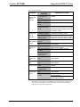
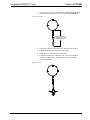
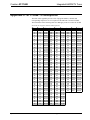
1
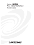
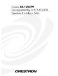
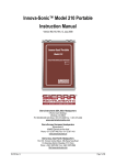
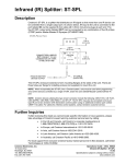
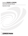
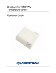
This document was prepared and written by the Technical Documentation department at:
Crestron Electronics, Inc.
15 Volvo Drive
Rockleigh, NJ 07647
1-888-CRESTRON
Crestron ST-TUNE
Integrated AM/FM/TV Tuner
Contents
Integrated AM/FM/TV Tuner: ST-TUNE
Description
Functional Description
Physical Description
Leading Specifications
Setup
Network Wiring
Preparation for Use
Identity Code
Firmware Upgrade
Programming with SIMPL Windows
Configure ST-TUNE Program
ST-TUNE and STI-TUNE Symbols
Basic Example Program
Advanced Example Program
Problem Solving
Troubleshooting
Further Inquiries
Future Updates
Future Firmware Upgrades
Appendix 1: High-Gain AM Antenna
Materials Required
Fabrication Instructions
Appendix 2: STI-TUNE TV Receptions
Appendix 3: Upgrade Firmware Version Prior to 2.17
Return and Warranty Policies
Merchandise Returns / Repair Service
CRESTRON Limited Warranty
Operations Guide - DOC. 5833A
1
1
1
2
6
8
8
9
10
11
14
15
15
20
21
22
22
24
24
24
25
25
25
27
28
35
35
35
Contents • i
Crestron ST-TUNE
Integrated AM/FM/TV Tuner
Integrated AM/FM/TV Tuner:
ST-TUNE
Description
Functional Description
The ST-TUNE is a Crestron remote control network (herein referred to as the
Cresnet system) optimized high-performance AM/FM/WX (Weather radio) and
television (TV) tuner. The ST-TUNE provides professional audio that connects
directly to and is accessed by a Cresnet system. The Cresnet system can store
virtually unlimited radio station and TV channel presets. The presets are available for
recall through Cresnet keypads, remote control devices, and/or touchpanels. The
frequency of the radio station or TV channel being received is displayed on the
ST-TUNE and can also be displayed on a touchpanel.
The ST-TUNE is also available as an international version with the unit
nomenclature of STI-TUNE. All of the features are identical with the exceptions of
TV reception formats and FM and TV input connectors. The ST-TUNE receives
National Television System Committee (NTSC) M/N format video and the
STI-
Operations Guide - DOC. 5833A
Integrated AM/FM/TV Tuner: ST-TUNE • 1
Integrated AM/FM/TV Tuner
Crestron ST-TUNE
Physical Description
The ST-TUNE, shown below, is housed in a black enclosure with silk-screened
labels on the front and rear panels. On the front panel are 12 light-emitting diodes
(LEDs) for indicating the status of the unit, the digital display for showing the band,
radio station or TV channel being received, two control buttons, and three function
selection buttons. All connections are made on the rear panel ports. There are four
rubber feet on the base of the unit for stability and to prevent slippage.
ST-TUNE Physical Views
2 • Integrated AM/FM/TV Tuner: ST-TUNE
Operations Guide - DOC. 5833A
Crestron ST-TUNE
Integrated AM/FM/TV Tuner
ST-TUNE Ports
Each ST-TUNE rear panel port has a silk-screened label. For the descriptions of the
ports, refer to the following diagrams and sections.
ST-TUNE Rear Panel
12VDC
1A
NET
NET
AUDIO
L
VIDEO
AM
FM
TV
R
CRESTRON ELECTRONICS INC. ROCKLEIGH, N.J. 07647 USA
STI-TUNE (International Version) Rear Panel
12VDC
1A
NET
NET
AUDIO
L
VIDEO
AM
FM
TV
R
CRESTRON ELECTRONICS INC. ROCKLEIGH, N.J. 07647 USA
12 VDC 1A
This direct current (DC) power socket connector is used to supply power via the
Operations Guide - DOC. 5833A
Integrated AM/FM/TV Tuner: ST-TUNE • 3
Integrated AM/FM/TV Tuner
Crestron ST-TUNE
AUDIO (L + R)
This pair of RCA jacks output the left (white center insulator) and right (red center
insulator) channel line-level audio to an audio processor such as the CNX-PAD8.
The audio can also be connected to the audio inputs of a TV monitor, audio switcher
and/or audio distribution equipment.
VIDEO
This RCA jack outputs composite TV video from the ST-TUNE. The center insulator
of this jack is yellow and may be connected to any video device that accepts a
composite input.
AM
This RCA jack is used to input AM radio signals via the supplied AM antenna. The
center insulator of this jack is white. Using a commercially available RCA extender
cable (not supplied but RadioShack® part numbers 42-2352 and 274-874
recommended), the antenna can be mounted outside of a “noisy” equipment rack.
For fabrication instructions of a high-gain AM antenna for use in areas of high
ambience interference or weak reception, refer to Appendix 1 that begins on page 25.
FM
This connector is used to input FM radio signals. The ST-TUNE uses a 75-ohm “F”
Type coaxial connector and the international STI-TUNE uses a 9.5 millimeter (mm)
“IEC” Type connector. The signals may be from cable input (if FM signal is
available), digital satellite receiver, FM antenna, weather station, etc.
TV
This connector is used to input TV channel audio and video signals. The ST-TUNE
uses a 75-ohm “F” Type coaxial connector and the STI-TUNE uses a 11-mm “IEC”
Type connector. The signals may be cable input, digital satellite receiver, TV
antenna, etc.
ST-TUNE Front Panel Indicators and Buttons
There are 12 LED indicators, one digital display, two control buttons, and three
function selection buttons located on the front panel of the ST-TUNE. For the
descriptions, refer to the diagram below and the following paragraphs.
ST-TUNE Front Panel
AM
AM/FM-TV TUNER
SIG
PWR
FM
WX
TV
PRE
BAND
NET
MONO
TUNE
SAP
SRCH
CRESTRON
MONO
MODE
ST - T U N E
PWR
This LED (green) illuminates when operating power is supplied to the ST-TUNE.
Operating power is supplied by the external power pack (included) or the network
wiring via the rear panel connectors.
4 • Integrated AM/FM/TV Tuner: ST-TUNE
Operations Guide - DOC. 5833A
Crestron ST-TUNE
Integrated AM/FM/TV Tuner
NET
This LED (yellow) indicates that the SIMPL program currently loaded in the control
system has a network device defined at the same NET ID code as the ST-TUNE. The
LED flashes when communication with the Cresnet system and the ST-TUNE is
occurring.
BAND INDICATORS AND DIGITAL DISPLAY
The AM, FM, WX (Weather Radio), or TV indicators contain four LEDs (red) to
display the active band of the ST-TUNE. The digital display shows the radio
frequency or TV channel being received.
RECEPTION INDICATORS
These three LEDs (red) indicate the reception status of the ST-TUNE. The LED
labeled SIG indicates the strength of the incoming FM signal, the steadier and
brighter the LED the stronger the signal. The MONO indicator illuminates when the
mono selector is activated while in the FM, WX or TV band and the SAP indicator
illuminates when the SAP selector is activated while in the TV band (regardless of
whether or not SAP information is being received).
NOTE: The SIG LED provides the most accurate indication of the incoming FM
signal after the ST-TUNE has reached optimum operating temperature
(approximately 10 minutes).
TUNING MODE INDICATORS
These three LEDs (red) indicate the tuning mode of the ST-TUNE. The LED labeled
PRE indicates that the preset mode (the preset functions are determined by the
control system program) is activated. The TUNE indicator illuminates when the
manual tuning mode is activated and SRCH indicates that search tuning is activated.
UP/DOWN CONTROL BUTTONS
During the PRE mode, the up or down control buttons cause the Cresnet control
system to perform a preset or pre-programmed function. If not programmed, these
buttons have no function during this mode. Refer to “Programming with SIMPL
Windows” on page 13 for further information. While in the TUNE mode, the up or
down buttons increment and decrement the radio or TV frequency by one step during
each press. If pressed and held, the ST-TUNE will rapidly tune up or down. If the
selected band supports the search tuning function, pressing either button during the
SRCH mode searches the radio or TV frequency range for the next strong incoming
signal.
NOTE: The SRCH mode performs most accurately after the ST-TUNE has reached
optimum operating temperature (approximately 10 minutes) and is receiving an
adequately strong signals. Refer to the Sense-High and Sense-Low entry of the
“ST-TUNE and STI-TUNE Symbol Input Descriptions” table on page 18 for further
information.
SELECTION BUTTONS
The selection buttons cycle the reception functions of the ST-TUNE. Repeatedly
pressing the BAND button cycles through the AM, FM, WX, and TV bands.
Pressing the MONO button toggles between the mono and stereo reception (for all
modes except AM in ST-TUNE, for all modes except AM and TV in international
version STI-TUNE) and the MODE button cycles through the preset, manual, or
search tuning modes.
Operations Guide - DOC. 5833A
Integrated AM/FM/TV Tuner: ST-TUNE • 5
Integrated AM/FM/TV Tuner
Crestron ST-TUNE
Leading Specifications
The five tables in this section provide summaries of the specifications for the
ST-TUNE. Dimensions and weight are rounded to the nearest hundredth unit.
Leading Specifications of the ST-TUNE
DETAILS
12VDC, external power pack or
9 Watts (24VDC @ 0.375A), network
3E
1
Version 1.51 or later with library update
file 115 later
6 • Integrated AM/FM/TV Tuner: ST-TUNE
Operations Guide - DOC. 5833A
Crestron ST-TUNE
Integrated AM/FM/TV Tuner
FM Tuner Specifications
DETAILS
Input Connector:
US "F" Type Coaxial, female, 75 ohms
International "IEC" Type Coaxial, 9.5mm male
87.5MHz to 107.9MHz
Frequency Range
11 (dBf)
Usable Sensitivity, Mono
74dB / 70dB
S/N Ratio @ 65 dBf, mono / stereo
0.05%
THD @ 1KHz mono/stereo
Sensitivity, Adjacent / Alternate Channel 5dB / 65dB
100dB
AM Rejection
55dB
Stereo Separation
45dB
1VRMS
Audio Output Level, Line @ 10k ohms
Operations Guide - DOC. 5833A
Integrated AM/FM/TV Tuner: ST-TUNE • 7
Integrated AM/FM/TV Tuner
Crestron ST-TUNE
NOTE: Equipment has been tested and found to comply with the limits for a Class
B digital device, pursuant to part 15 of the FCC Rules. These limits are designed to
provide reasonable protection against harmful interference in a residential
installation. The equipment generates, uses and can radiate radio frequency energy
and, if not installed and used in accordance with the instructions, may cause harmful
interference to radio communications. However, there is no guarantee that
interference will not occur in a particular installation. If this equipment does cause
harmful interference to radio or television reception, which can be determined by
turning the equipment off and on, the user is encouraged to try to correct the
interference by one or more of the following measures:
n
Reorient or relocate the receiving antenna.
n
Increase the separation between the equipment and receiver.
n
Connect the equipment into an outlet on a circuit different from that to which the
receiver is connected.
n
Consult the dealer or an experienced radio/TV technician for help.
As of the date of manufacture, this unit has been tested and found to comply with
specifications for CE marking.
Setup
Network Wiring
CAUTION: Crestron modular cables are rated for a maximum of two (2) amperes.
Do not exceed this current capacity for any modular device. If more current is
required, connect an appropriate external power pack to the device.
NOTE: If making category 5 connections to the Cresnet peripherals, refer to the
latest revision of the Cresnet Mini Network CAT 5 Interconnect Drawing (Doc.
5819). This document can be obtained from the Products page (PRODUCT
MANUALS, Software and Wiring Diagrams section) or Downloads page (CABLES
and MANUAL Libraries, search for CAT5.PDF) of Crestron’s website
(www.crestron.com). New users are required to register to obtain access to the FTP
site.
NOTE: Review the latest revision of the Network Modular Cable Requirements
(Doc. 5682). This document can be obtained from the Products page (PRODUCT
MANUALS, Software and Wiring Diagrams section) or Downloads page (CABLES
and MANUAL Libraries, search for MODULAR.PDF) of Crestron’s website
(www.crestron.com).
NOTE: The CNHBLOCK should be used when wiring multiple Cresnet devices to
a system. Use only Crestron modular cables when making connections to the
CNHBLOCK modular ports. DO NOT use standard, modular 6-conductor telephone
cables. Most telephone cables are wired in a crisscross fashion and are not
compatible with Crestron equipment.
8 • Integrated AM/FM/TV Tuner: ST-TUNE
Operations Guide - DOC. 5833A
Crestron ST-TUNE
Integrated AM/FM/TV Tuner
When calculating the wire gauge for a particular Cresnet run, the length of the run
and the load factor of each network unit to be connected must be taken into
consideration. If Cresnet units are to be daisy-chained on the run, the load factor of
each unit to be daisy-chained must be added together to determine the load factor of
the entire chain. If the unit is a home-run from a Crestron system power supply
network port, the load factor of that unit is the load factor of the entire run. The
length of the run in feet and the load factor of the run should be used in the following
resistance equation to calculate the value on the right side of the equation.
Resistance Equation
R < 40,000
L x LF
Where: R = Resistance (refer to next table).
L = Length of run (or chain) in feet.
LF = Load factor of entire run (or chain).
The required wire gauge should be chosen such that the resistance value is less than
the value calculated in the resistance equation. Refer to the table below.
Wire Gauge Values
RESISTANCE (R)
WIRE GAUGE
4
6
10
15
13
16
18
20
22
24 (Double-CAT 5)
NOTE: All Cresnet wiring must consist of two twisted-pairs. One twisted pair is the
+24V conductor and the GND conductor and the other twisted pair is the Y
conductor and the Z conductor.
NOTE: When daisy-chaining Cresnet units, always twist the ends of the incoming
wire and outgoing wire which share a pin on the network connector. After twisting
the ends, tin the twisted connection with solder. Apply solder only to the ends of the
twisted wires. Avoid tinning too far up the wires or the end becomes brittle. After
tinning the twisted ends, insert the tinned connection into the Cresnet connector and
tighten the retaining screw. Repeat the procedure for the other three conductors.
Preparation for Use
Refer to the hookup diagram on the next page which shows ST-TUNE connections.
Other than making the power connection last, complete the connections in any order.
NOTE: Refer to the latest revision of the Crestron Network Modular Cable
Requirements (Doc. 5682) when making connections to the ports labeled NET. This
document can be obtained from the Products page (PRODUCT MANUALS,
Software and Wiring Diagrams section) or Downloads page (CABLES and
MANUAL Libraries, search for MODULAR.PDF) of Crestron’s website
(www.crestron.com). New users are required to register to obtain access to the FTP
site.
NOTE: The external power pack and AM antenna are supplied with the ST-TUNE.
All other modular cables, patch cords, or coaxial cables are not provided.
Operations Guide - DOC. 5833A
Integrated AM/FM/TV Tuner: ST-TUNE • 9
Integrated AM/FM/TV Tuner
Crestron ST-TUNE
NOTE: The location of the ST-TUNE is an important factor in the AM radio
reception. The reception is also dependent on its placement and the construction of
the building, locate the unit outside of any metal enclosures to achieve the best
performance. A commercially available RCA extender cable (not supplied but
RadioShack® part numbers 42-2352 and 274-874 are recommended), may be used to
mount the antenna outside of a “shielded area or a “noisy” equipment rack.
NOTE: For fabrication instructions of a high-gain AM antenna for use in areas of
high ambience interference or weak reception areas, refer to Appendix 1 that begins
on page 25.
NOTE: The diagram below shows the US version ST-TUNE that requires “F” type,
75 ohm coaxial connectors for the FM and TV inputs. The international version
STI-TUNE requires “IEC” connectors, 9.5mm for FM and 11mm for TV.
Hookup Diagram for ST-TUNE
NET
NET
AUDIO
L
10 • Integrated AM/FM/TV Tuner: ST-TUNE
VIDEO
AM
FM
TV
R
Operations Guide - DOC. 5833A
Crestron ST-TUNE
Integrated AM/FM/TV Tuner
1.
Attach one of the ST-TUNEs to the control system (verify that the
software is running).
2.
From the SIMPL Windows or VT Pro-e menu, select Tools | Viewport
to open the Crestron Viewport.
3.
From the Viewport menu, select Functions | Set Network ID. The
software checks the baud rate and then opens the “Set Network ID”
dialog box.
4.
In the “Set Network ID” dialog box, select the ST-TUNE from the
Current Network Devices text window.
5.
From the Choose the new network ID for the selected device (Hex): text
box, select the new Net ID for the ST-TUNE.
6.
Click Set ID to initiate the change. This will display the “ID command
has been sent” dialog box.
7.
In the “Command Complete” dialog box, click OK.
8.
In the Current Network Devices text window, verify the NET ID code.
9.
In the “Set Network ID” dialog box, click Close.
NOTE: The new NET ID code may also be verified by selecting Diagnostics |
Report Network Devices in the Viewport (alternatively, depress F4).
10. Repeat this procedure for each ST-TUNE to be added to the Cresnet
system.
Firmware Upgrade
To upgrade the firmware of a ST-TUNE, a local PC that contains the Crestron
Viewport (available in SIMPL Windows or VT Pro-e) is required. To connect the PC
to the control system, refer to the “Obtaining Communications” section of the
Operators Guide supplied with the appropriate control system. The latest version of
the Operations Guides can be obtained from the Products page (PRODUCT
MANUALS, Hardware section) or Downloads page (MANUAL Library) of
Crestron’s website (www.crestron.com). New users are required to register in order
to obtain access to the FTP site.
Firmware upgrade files are obtained from the What’s New page (Other Products
section) or the Downloads page (UPGRADES Library, search for RADIOFIX.EXE)
of Crestron’s website.
To upgrade ST-TUNE firmware, complete the following steps.
1.
Make sure that no programs accessing the COM port of the PC.
2.
At the PC, start SIMPL Windows or VT Pro-e.
3.
From the SIMPL Windows or VT Pro-e menu bar, select Tools |
Viewport to open the Crestron Viewport.
NOTE: SIMPL Windows may open with an opening splash screen and may display
the “What do you want to do?” dialog box. If so, close the dialog box and continue.
4.
Operations Guide - DOC. 5833A
Refer to diagram on the next page. From the Viewport menu, select
Setup | Communications settings (alternatively, depress Alt+D) to
open the Port Settings dialog box.
Integrated AM/FM/TV Tuner: ST-TUNE • 11
Integrated AM/FM/TV Tuner
Crestron ST-TUNE
Accessing the Port Settings Dialog Box
5.
Refer to the dialog box shown below and verify the communications
settings. Make sure that parity is set to None, data bits to Eight, and
XModem is selected.
NOTE: If performing a firmware upgrade via Ethernet, select TCP/IP as the
connection type and provide the IP address.
Port Settings Dialog Box
12 • Integrated AM/FM/TV Tuner: ST-TUNE
Operations Guide - DOC. 5833A
Crestron ST-TUNE
Integrated AM/FM/TV Tuner
6.
Refer to diagram below. From the Viewport menu, select Diagnostics |
Report Network Devices (alternatively, depress F4).
Accessing the Network Devices
7.
In the Viewport return display, observe the firmware version of the
ST-TUNE.
8.
Perform the appropriate step.
8a. If the firmware version is version 2.17 or later, continue with this
procedure.
8b. If the firmware version is prior to version 2.17, proceed to step 8
of “Appendix 3” that begins on page 28.
9.
As shown below, select File Transfer | Load Network Device from
the Viewport menu.
Select Load Network Device
Operations Guide - DOC. 5833A
Integrated AM/FM/TV Tuner: ST-TUNE • 13
Integrated AM/FM/TV Tuner
Crestron ST-TUNE
10. Refer to the diagram below. Select the NET ID of the ST-TUNE and
then click OK.
“Select Network ID” Dialog Box
11. As shown below, browse to the firmware directory, select the
downloaded firmware (UPG) file and click Open. The transfer will
complete automatically.
Select Firmware (UPG) File
NOTE: When the external power pack is disconnected from the ST-TUNE,
operating power will automatically switch to Cresnet power supplied via the NET
connector(s). To remove power from the unit, make sure both external power pack
and NET connector(s) are removed.
12. Remove operating power from the ST-TUNE, wait several seconds and
reconnect power.
13. Close the Viewport, exit SIMPL Windows or VT Pro-e, and disconnect
the programming cable from the PC and the control system.
Programming with SIMPL Windows
SIMPL (Symbol Intensive Master Programming Language) is an easy-to-use
programming language that is completely integrated and compatible with all
Crestron system hardware. The objects that are used in SIMPL are called symbols.
SIMPL Windows offers drag and drop functionality in a familiar Windows®
environment.
SIMPL Windows is Crestron's software for programming Crestron control systems.
It provides a well-designed graphical environment with a number of workspaces
(i.e., windows) in which a programmer can select, configure, program, test, and
monitor a Crestron control system.
14 • Integrated AM/FM/TV Tuner: ST-TUNE
Operations Guide - DOC. 5833A
Crestron ST-TUNE
Integrated AM/FM/TV Tuner
The next four sections describe a ST-TUNE within a SIMPL Windows program. The
first section provides initial configuration information, the second section details the
SIMPL symbol, the third section describes how a basic example program works by
using a textual description and a block diagram, and the fourth section describes the
screens of an advanced example program.
NOTE: The following descriptions assume that the reader has knowledge of SIMPL
Windows. If not, refer to the extensive help information provided with the software.
NOTE: VT Pro-e (version 2.1.8 or later) is required for the ST-TUNE example
touchpanels. The latest software version can be obtained from the What’s New page
(VisionTools Pro-e section) or Downloads page (VTPRO-E Library) of Crestron’s
website (www.crestron.com). New users are required to register in order to obtain
access to the FTP site.
NOTE: There is no need to recreate the ST-TUNE example touchpanels or example
SIMPL Windows programs. Both are available from the Downloads page
(EXAMPLES Library) of Crestron’s website (www.crestron.com). Search for
STTUNEA.ZIP that contains a basic example and STTUNEB.ZIP that contains an
advanced example. Each example contains the program and all associated files
required to complete the program.
Configure ST-TUNE Program
To create a program with a ST-TUNE, in the Configuration Manager of SIMPL
Windows, refer to the table below for initial configuration information.
Configure ST-TUNE Program
DEVICE
LIBRARY
SYMBOL
REQUIRED
DROP
WHERE
Control
Systems
Desired control
system
System Views
Network
Control
Modules
ST-TUNE or
STI-TUNE
System Views,
Cresnet Units
ADDITIONAL
SETUP
Refer to the documentation
supplied with the control system
for additional setup information.
CHANGE NET ID (OPTIONAL) Double-click on ST/I-TUNE (or
single-click then right mouseclick) on ST/I-TUNE. Select
Configure. Select NET ID then
select desired hexidecimal ID.
ST-TUNE and STI-TUNE Symbols
The diagrams on the next two pages show the ST-TUNE and STI-TUNE symbols in
SIMPL Windows. The two tables following the diagrams list the inputs and outputs,
respectively, and their functional descriptions.
NOTE: The US version ST-TUNE and international version STI-TUNE have the
same default NET ID. If both ST-TINE and STI-TUNE are used in the same Cresnet
system, refer to “Identity Code” that begins on page 10 for further information.
NOTE: All signals listed in the following tables apply to the US version ST-TUNE
and international version STI-TUNE except where noted.
Operations Guide - DOC. 5833A
Integrated AM/FM/TV Tuner: ST-TUNE • 15
Integrated AM/FM/TV Tuner
Crestron ST-TUNE
NOTE: All signals listed in the following tables are DIGITAL signals unless noted
otherwise. A digital signal can be high (logic level of 1), low (logic level of 0), and
also have rising edge (when it goes from low to high) and falling edge (from high to
low) transitions. Depending upon how the symbol was created, symbol inputs may
work at the logic levels or on transitions.
Detail View of the ST-TUNE Symbol in SIMPL Windows’ Programming Manager
16 • Integrated AM/FM/TV Tuner: ST-TUNE
Operations Guide - DOC. 5833A
Crestron ST-TUNE
Integrated AM/FM/TV Tuner
Detail View of the STI-TUNE Symbol in SIMPL Windows’ Programming Manager
Operations Guide - DOC. 5833A
Integrated AM/FM/TV Tuner: ST-TUNE • 17
Integrated AM/FM/TV Tuner
Crestron ST-TUNE
ST-TUNE and STI-TUNE Symbols Input Descriptions
INPUT(S)
FUNCTION(S)
These signals perform the same functions as pressing the UP or
DOWN buttons on the front panel. NOTE: The front panel buttons
auto-increment after a preset period of time. These UP and DN
signals engage only once on the rising edge. Therefore, in the TUNE
mode, the UP signal increments the station once.
This signal cycles through the AM, FM, WX, and TV bands. The band
Func
is selected on the rising edge.
AM, FM, WX, Each of these signals selects one of the four bands directly. The
band is selected on the rising edge.
TV
This signal performs the same function as pressing the MODE button
Mode
on the front panel. (The MODE function cycles through PRE, TUNE,
SRCH tuning modes.) The MODE is selected on the rising edge.
Each of these signals selects one of the three modes directly. The
Pre, Tune,
function is selected on the rising edge. These will change the function
Srch
of the UP and DOWN buttons. (Refer to Pre-F, Tune-F, and Srch-F in
the next table for related information.) NOTE: In PRE mode, no
function is performed, PRE mode must be programmed in SIMPL
(typically this would be logic to recall stations; see the ST-TUNEB.ZIP
program examples).
This signal (not active in AM mode) performs the same function as
Mono
pressing the MONO button on the front panel. This function toggles
on each rising edge.
These signals select one of the mono modes directly. The function is
Mono-On,
selected on the rising edge.
Mono-Off
ST-TUNE ONLY - These signals turns SAP reception on or off during
SAP-On,
TV mode only. This mode is selected on the rising edge.
SAP-Off
Sense-High, These signals directly adjust the sensitivity of tuning. The sensitivity
is selected on the rising edge. NOTE: SENSE-HIGH allows the unit
Sense-Low
to recognize weaker stations during the search mode. (Refer to SigStrength in the next table for related information.)
Disable-Lcl- When this signal is high, the local functionality of the front panel
buttons is disabled. (The button presses are still reported into the
Btns
program on the output of the symbol.)
Off-Air, STD, ST-TUNE ONLY - These are four modes of TV reception. In each
mode, the channels map to different frequencies. The mode is
IRC, HRC
effected on the rising edge of the next frequency change.
This analog signal is a number that sets the AM frequency of the
AM-Station
unit. Valid AM numbers are 530d through 1710d. Valid AM
increments are by 10, such as 1010d, 1020d, etc. NOTE: If not in the
AM mode, the unit will not go into AM mode when this signal is
received on this line. The signal will set that value for the next time
the unit is put into AM mode.
This analog signal is a number that sets the FM frequency. Valid FM
FM-Station
numbers are 8950d through 10790d. The number has an implied
decimal point 2 digits from the end and must be sent in this format.
For example, to go to 102.7 FM, the analog number to be sent is
10270d. FM stations are only valid on analog increments of 5,
therefore 10271d is not valid and will go to the next lowest station,
10270d. NOTE: If not in the FM mode, the unit will not go into FM
mode when this signal is received on this line. The signal will set that
value for the next time the unit is put into FM mode.
Up, Dn
18 • Integrated AM/FM/TV Tuner: ST-TUNE
Operations Guide - DOC. 5833A
Crestron ST-TUNE
Integrated AM/FM/TV Tuner
ST-TUNE and STI-TUNE Symbols Input Descriptions (continued)
INPUT(S)
WX-Station
TV-Station
FUNCTION(S)
This analog signal is a number that sets WX frequency. Valid
weather radio numbers are 16240d through 16255d. The number has
an implied decimal point 2 digits from the end and must be sent in
this format. For example, to go to 162.40, the analog number to be
sent is 16240d. Valid WX station increments are by 1, such as
162.41, 162.42. NOTE: If not in the WX mode, the unit will not go
into WX mode when this signal is received on this line. The signal will
set that value for the next time the unit is put into WX mode.
This analog signal is a number that sets the TV station (channel).
Valid TV stations are different depending on the mode. (Refer to the
"TV Tuner Specifications" in the "Leading Specifications" section that
begins on page 7). Channel numbers are incremented by 1.
NOTE: All outputs listed in the following table require DIGITAL signals unless
noted otherwise.
ST-TUNE and STI-TUNE Symbols Output (Feedback) Descriptions
OUTPUT(S)
Up-B, Dn-B
Func-B
AM-F, FM-F,
WX-F, TV-F
Mode-B
Pre-F, TuneSrch-F
Mono-B
Mono-ON-F,
Mono-OFF-F
Stereo-Detect
SAP-On-F,
SAP-Off-F
FUNCTION(S)
These signals are high as long as the UP or DOWN button on the
front panel is being pressed and held.
This signal is high as long as the FUNC button on the front panel is
being pressed and held.
This is an interlocked group of signals. The signal that is high is the
current band of the unit.
This signal is high as long as the MODE button on the front panel is
being pressed and held.
This is an interlocked group of signals. The signal that is high is the
current mode of the unit.
This signal is high as long as the MONO button on the front panel is
being pressed and held.
This is an interlocked group of signals. The signal that is high is the
current mode of the unit.
This signal is high when the current station is being received in
stereo. This signal is active only during the FM mode.
ST-TUNE ONLY - This is an interlocked group of signals. When the
SAP mode is on (TV mode only), SAP-ON-F is high. The LED on the
front panel indicates if SAP is actually being received.
These four analog numbers correspond to the current state each
band of the unit.
AM-Station-F,
FM-Station-F,
WX-Station-F,
TV-Station-F
Sig-Strength This 8-step analog signal is a number indicating how strong the
station is being received. The steps are decimal 0, 8191, 16382,
24573, 32764, 40955, 49146, 57337 or hexadecimal 0, 1FFF, 3FFE,
5FFD, 7FFC, 9FFB, BFFA, DFF9. This signal is active only during the
FM mode. NOTE: Best SRCH function recognition is achieved with a
signal strength of 24573 (5FFD) or above for low-sensitivity or 40955
(9FFB) or above for high-sensitivity.
Operations Guide - DOC. 5833A
Integrated AM/FM/TV Tuner: ST-TUNE • 19
Integrated AM/FM/TV Tuner
Crestron ST-TUNE
Basic Example Program
NOTE: There is no need to recreate the basic example SIMPL Windows program.
The program is available from the Downloads page (EXAMPLES Library) of
Crestron’s website (www.crestron.com). Search for STTUNEA.ZIP. New users are
required to register in order to obtain access to the FTP site.
The program provides the ability to select a band, tune a station, and engage
hardcoded presets from a touchpanel. For descriptions of the basic example
touchpanel and basic program, refer to the following sections.
Basic Example Touchpanel
The example touchpanel shown below demonstrates the basic capabilities of the
ST-TUNE. The band selection buttons are used to select the desired band and the up
and down buttons tune the frequency. The preset buttons recall station presets that
are stored in the control system SIMPL program.
NOTE: VT Pro-e is required for the ST-TUNE example basic touchpanel. The
latest version of VT Pro-e can be obtained from the What’s New page (VisionTools
Pro-e section) or Downloads page (VTPRO-E Library) of Crestron’s website
(www.crestron.com).
Basic Example Touchpanel
How the Basic Example Program Works
The example SIMPL program for the ST-TUNE is shown on the next page as a block
diagram. Certain inputs and outputs have been rearranged or omitted for clarity. The
touchpanel and ST-TUNE symbols are common to all (AM, FM, WX and TV)
functions but the diagram shows details the signals and logic for the AM function
only. The logic specifically for the AM functions are OR symbol S-2.1 and analog
20 • Integrated AM/FM/TV Tuner: ST-TUNE
Operations Guide - DOC. 5833A
Crestron ST-TUNE
Integrated AM/FM/TV Tuner
initialize symbol S-2.2 (contains the station presets). For the program logic of all
functions, refer to the table below.
In the block diagram, the signals labeled A are feedback to the touchpanel.
Basic Example Function Symbols and Parameters
Advanced Example Program
NOTE: There is no need to recreate the advanced example SIMPL Windows
program. The program is available from the Downloads page (EXAMPLES Library)
of Crestron’s website (www.crestron.com). Search for STTUNEB.ZIP. New users
are required to register in order to obtain access to the FTP site.
This example program utilizes most of the features of the ST-TUNE and provides
logic that can be reused for different applications. The opening screen of this
program allows a choice of setup, tuning, preset recall, or preset setup. Refer to the
following sections for brief descriptions of the individual screens.
Setup Screen
The setup screen allows MONO mode to be turned on or off, SAP to be turned on or
off, the tuning sensitivity to be set, and the TV reception mode to be set. (The
Operations Guide - DOC. 5833A
Integrated AM/FM/TV Tuner: ST-TUNE • 21
Integrated AM/FM/TV Tuner
Crestron ST-TUNE
functions of SAP on or off and setting the TV reception mode are not applicable for
the international version STI-TUNE.) The screen also shows the signal strength as a
percentage.
One of the features of the program is customizable presets, the name of the preset
and the station can be customized at runtime. The INITIALIZE ALL PRESETS
button sets all names (labels) to empty, and sets the station to 102.70 FM.
NOTE: It is often useful to put a known quantity into presets, otherwise whatever is
in system memory will be used which could provide undesirable results.
Tuning Screen
The tuning screen allows the station to be selected. The values of each station are
displayed with digital gauges. Note that VT Pro-e allows analog numbers to be
displayed with implied decimal points so that FM and WX stations may be formatted
properly. The stations can be tuned directly with the UP and DOWN BUTTONS.
The auto-repeat logic has been programmed in via the “button-repeater” modules.
A station frequency may be directly entered on the keypad. The display above the
keypad dynamically changes based on the type of station selected. For example, in
FM mode, the format will be displayed as XXX.XX. In AM Mode, it will be
displayed as XXXX. The station is entered by inputting a full number (such as 8950
for 89.50, 10270 for 102.70) and then pressing ENTER. The station values are
checked after pressing ENTER to be sure that they are within the proper ranges.
Preset Recall
The preset recall screens show the 25 presets. When a preset is selected, it is recalled
to the ST-TUNE.
Setup Preset
The setup preset screen allows the user to customize the presets. The user can enter a
name and the station number. The BAND is retained, Station is retained, and TV
Mode is retained. When recalled, Band, Station, and TV Mode (not applicable for the
international version STI-TUNE) are set up. This allows a preset to be completely
customizable, unlike most radios where there are banks of FM Presets and AM
Presets. The touchpanel contains on-screen help. The Crestron module “Text Entry
for 25 Fields” was used to program the preset names.
Problem Solving
Troubleshooting
The table on the next page provides corrective action for possible trouble situations.
If further assistance is required, please contact a Crestron customer service
representative.
22 • Integrated AM/FM/TV Tuner: ST-TUNE
Operations Guide - DOC. 5833A
Crestron ST-TUNE
Integrated AM/FM/TV Tuner
ST-TUNE Troubleshooting
TROUBLE
Green PWR
indicator LED
does not
illuminate.
POSSIBLE
CAUSE(S)
CORRECTIVE ACTION
VAC at wall outlet or
power strip is not
available.
External power pack
faulty.
No power on network
wiring.
Not enough current
available on network
wiring.
Verify VAC at wall outlet or power strip is
available.
Replace external power pack.
Verify network wiring.
If using a CEN-TVAV, CN-TVAV, or
ST-CP as a control system, the ST-TUNE
requires the supplied external power pack
for sufficient current.
Yellow NET
ST-TUNE is not comm- Check network cabling for solid
indicator LED
unicating on network.
connections and correct pinouts.
does not
NET ID is not set to
Enter Viewport and poll the network (F4).
illuminate.
match the NET ID of the Verify that the NET ID for the ST-TUNE is
SIMPL program.
properly set to match the SIMPL program.
Audio or video
Cable(s) not connected Verify cable(s) is securely connected.
output missing or properly.
not clear.
Cable(s) connections
Clean cable connection(s) with electrical
dirty.
contact cleaner.
AM antenna connection Clean AM antenna connection with
AM radio
dirty.
electrical contact cleaner.
reception not
AM antenna placement Refer to note 1 following this table.
clear.
not good.
Refer to note 2 following this table.
ST-TUNE located in
outer fringe or bad
reception area.
Clean FM input connection with electrical
FM or WX radio FM input connection
dirty.
contact cleaner.
reception not
clear.
TV reception not TV input connection
Clean TV input connection with electrical
clear.
dirty.
contact cleaner.
ST-TUNE is in MONO Press MONO button to deselect mono
TV band does
reception.
not receive SAP. mode.
Received channel does No corrective action.
not support SAP.
SRCH function FM input connection
Clean FM input connection with electrical
does not work
dirty.
contact cleaner.
properly.
Station signal strength Verify good signal strength due to
too low.
antenna placement.
In control system program, select the
Sense-High symbol input.
1
Operations Guide - DOC. 5833A
The location of the ST-TUNE is an important factor in the AM radio reception. The
reception is also dependent on its placement and the construction of the building,
locate the unit outside of any metal enclos
Integrated AM/FM/TV Tuner: ST-TUNE • 23
Integrated AM/FM/TV Tuner
Crestron ST-TUNE
Further Inquiries
If after reviewing this Operations Guide, you cannot locate specific information or
have questions, please take advantage of Crestron's award winning customer service
team by calling:
•
In the US and Canada, call Crestron’s corporate headquarters at
1-888-CRESTRON [1-888-273-7876] or 1-201-767-3400.
•
In Europe, call Crestron International at +32-15-50-99-50.
•
In Asia, call Crestron Asia at +852-2341-2016.
•
In Latin America, call Crestron Latin America at +525-260-4336.
For local support from exclusive Crestron factory-trained personnel call:
•
In Australia, call Soundcorp at +613-9488-1555.
•
In New Zealand, call Amber Technologies at +649-410-8382.
Future Updates
As Crestron improves functions, adds new features, and extends the capabilities of
the ST-TUNE, additional information and programming examples may be made
available as manual updates. These updates are solely electronic and serve as
intermediary supplements prior to the release of a complete technical documentation
revision.
The Downloads page of the Crestron website (www.crestron.com) directs the reader
to the location and description of each update. Check the site periodically for update
availability and its subjective value.
Future Firmware Upgrades
As Crestron improves functions, adds new features, and extends the capabilities of
the ST-TUNE, firmware upgrades may be made available. The upgrade files can be
obtained from the What’s New page (Other Products section) or the Downloads page
(UPGRADES Library) of Crestron’s website. New users are required to register in
order to obtain access to the FTP site.
24 • Integrated AM/FM/TV Tuner: ST-TUNE
Operations Guide - DOC. 5833A
Crestron ST-TUNE
Integrated AM/FM/TV Tuner
Appendix 1: High-Gain AM Antenna
This appendix provides fabrication instructions of a high-gain AM antenna for use in
areas of high ambience interference or weak reception. The antenna consists of a
looped wire and connector.
Materials Required
For the list of materials required for antenna fabrication, refer to the table below. All
materials are available commercially. The only tools required for antenna fabrication
are a soldering iron and soldering supplies.
Antenna Fabrication Materials
MATERIAL
QUANTITY
Wire, 22 gauge, UL AWM style 1061, 300 volt
Tie wraps, plastic (or twist ties)
RCA plug, solderable
240 inches *
Eight (8) minimum
One (1) **
*
Alpha Wire Corp. part number 3251 recommended.
**
Keystone part number 1085-B or RadioShack® 274-319 recommended.
Fabrication Instructions
To fabricate a high-gain AM antenna, perform the following steps.
1.
Extend wire approximately 36-inches.
2.
As shown below, create 15 5-inch (approximately) diameter loops with
the wire and wrap or twist tie the loop in at least eight (8) equidistant
places.
Create 15 Loops
15 LOOPS AT
APPROXIMATELY
5-INCHES DIAMETER
SECURE LOOPS WITH
AT LEAST EIGHT PLASTIC
TIE WRAPS OR TWIST TIES
APPROXIMATELY
36-INCHES
3.
Operations Guide - DOC. 5833A
Bring the ends of the wire together.
Integrated AM/FM/TV Tuner: ST-TUNE • 25
Integrated AM/FM/TV Tuner
Crestron ST-TUNE
4.
As shown below, twist the wires together at two (2) turns per inch
until the length of the twisted wires is approximately 34-inches.
Twist Wires Together
APPROXIMATELY
34-INCHES WITH TWO
TURNS PER INCH
5.
If necessary, trim the ends of the wire to make them even. Strip
1/4-inch of insulation from each end of the wire.
6.
Install the RCA connector cap onto the wires.
7.
Using the soldering iron, solder each end of the wire to the RCA
connector as shown below. (Solder either end of wire to either
connector terminal.)
Solder Connector
26 • Integrated AM/FM/TV Tuner: ST-TUNE
Operations Guide - DOC. 5833A
Crestron ST-TUNE
Integrated AM/FM/TV Tuner
Appendix 2: STI-TUNE TV Receptions
The table in this appendix provides a list of program numbers, channels and
corresponding frequencies for TV reception of international version STI-TUNE.
The information in the following table does not apply to the US version ST-TUNE.
STI-TUNE TV Programs, Channels and Frequencies
Operations Guide - DOC. 5833A
Prog
Chan
MHz
Prog
Chan
MHz
Prog
Chan
MHz
1
2
3
4
5
6
7
8
9
10
11
12
13
14
15
16
17
18
19
20
21
22
23
24
25
26
27
28
29
30
31
32
33
34
35
36
37
38
39
40
2
2a
3
4
5
6
7
8
9
10
11
12
21
22
23
24
25
26
27
28
29
30
31
32
33
34
35
36
37
38
39
40
41
42
43
44
45
46
47
48
48.25
49.75
55.25
62.25
175.25
182.25
189.25
196.25
203.25
210.25
217.25
224.25
471.25
479.25
487.25
495.25
503.25
511.25
519.25
527.25
535.25
543.25
551.25
559.25
567.25
575.25
583.25
591.25
599.25
607.25
615.25
623.25
631.25
639.25
647.25
655.25
663.25
671.25
679.25
687.25
41
42
43
44
45
46
47
48
49
50
51
52
53
54
55
56
57
58
59
60
61
62
63
64
65
66
67
68
69
70
71
72
73
74
75
76
77
78
79
80
49
50
51
52
53
54
55
56
57
58
59
60
61
62
63
64
65
66
67
68
69
S01
S02
S03
S1
S2
S3
S4
S5
S6
S7
S8
S9
S10
E5
E6
E7
E8
E9
E10
695.25
703.25
711.25
719.25
727.25
735.25
743.25
751.25
759.25
767.25
775.25
783.25
791.25
799.25
807.25
815.25
823.25
831.25
839.25
847.25
855.25
69.25
76.25
83.25
105.25
112.25
119.25
126.25
133.25
140.25
147.25
154.25
161.25
168.25
175.25
182.25
189.25
196.25
203.25
210.25
81
82
83
84
85
86
87
88
89
90
91
92
93
94
95
96
97
98
99
100
101
102
103
104
105
106
107
108
109
110
111
112
113
E11
E12
S11
S12
S13
S14
S15
S16
S17
S18
S19
S20
S21
S22
S23
S24
S25
S26
S27
S28
S29
S30
S31
S32
S33
S34
S35
S36
S37
S38
S39
S40
S41
217.25
224.25
231.25
238.25
245.25
252.25
259.25
266.25
273.25
280.25
287.25
294.25
303.25
311.25
319.25
327.25
335.25
343.25
351.25
359.25
367.25
375.25
383.25
391.25
399.25
407.25
415.25
423.25
431.25
439.25
447.25
455.25
463.25
Integrated AM/FM/TV Tuner: ST-TUNE • 27
Integrated AM/FM/TV Tuner
Crestron ST-TUNE
Appendix 3: Upgrade Firmware Version Prior to 2.17
This appendix provides firmware upgrade instructions for an ST-TUNE with a
firmware version prior to 2.17. To upgrade the firmware, complete the following
steps.
CAUTION: If the ST-TUNE contains firmware version 2.17 or later, DO NOT
perform this procedure or the unit will have to be returned to Crestron.
1.
Make sure that no programs accessing the COM port of the PC.
2.
At the PC, start SIMPL Windows or VT Pro-e.
3.
From the SIMPL Windows or VT Pro-e menu bar, select Tools |
Viewport to open the Crestron Viewport.
NOTE: SIMPL Windows may open with an opening splash screen and may display
the “What do you want to do?” dialog box. If so, close the dialog box and continue.
4.
Refer to diagram below. From the Viewport menu, select Setup |
Communications settings (alternatively, depress Alt+D) to open the
Port Settings dialog box.
Accessing the Port Settings Dialog Box
5.
Refer to the dialog box shown on the next page and verify the
communications settings. Make sure that parity is set to None, data bits
to Eight, and XModem is selected.
NOTE: If performing a firmware upgrade via Ethernet, select TCP/IP as the
connection type and provide the IP address.
28 • Integrated AM/FM/TV Tuner: ST-TUNE
Operations Guide - DOC. 5833A
Crestron ST-TUNE
Integrated AM/FM/TV Tuner
Port Settings Dialog Box
6.
Refer to diagram below. From the Viewport menu, select Diagnostics |
Report Network Devices (alternatively, depress F4).
Accessing the Network Devices
7.
Operations Guide - DOC. 5833A
In the Viewport return display, observe the firmware version of the
ST-TUNE.
Integrated AM/FM/TV Tuner: ST-TUNE • 29
Integrated AM/FM/TV Tuner
Crestron ST-TUNE
CAUTION: If the ST-TUNE contains firmware version 2.17 or later, DO NOT
continue this procedure or the unit will have to be returned to Crestron. Perform
“Firmware Upgrade” that begins on page 11.
8.
Refer to diagram on the next page. From the Viewport menu, select
Setup | Communications settings (alternatively, depress Alt+D) to
open the Port Settings dialog box.
Accessing the Port Settings Dialog Box
9.
Refer to the diagram below. In the “Line Pacing for ASCII Uploads”
text field, enter 500 and select ASCII as the “Mode for Network
Transfers”.
Port Settings Dialog Box for ASCII Upload
30 • Integrated AM/FM/TV Tuner: ST-TUNE
Operations Guide - DOC. 5833A
Crestron ST-TUNE
Integrated AM/FM/TV Tuner
10. Enter the following key sequence to (as previously defined for the
product) ESC, X, R, ID, ENTER. On the front panel of the unit, the
PRE, TUNE, SRCH plus either the AM, FM, WX, or TV LEDs will be
illuminated. If the return ID command is executed from the Viewport,
the display will show “BOOT”.
11. As shown below, select File Transfer | General File Transfer |
ASCII Upload from the Viewport menu.
Select ASCII Upload
12. As shown below, browse to the firmware directory, select the
downloaded loader (HEX) file and click Open. The transfer will
complete in approximately 3-1/2 minutes.
Select Loader (HEX) File
13. Select Diagnostics | Report Network Devices in the Viewport
(alternatively, depress F4) and observe Viewport return display show
“BOOT”.
NOTE: When the external power pack is disconnected from the ST-TUNE,
operating power will automatically switch to Cresnet power supplied via the NET
connector(s). To remove power from the unit, make sure both external power pack
and NET connector(s) are removed.
Operations Guide - DOC. 5833A
Integrated AM/FM/TV Tuner: ST-TUNE • 31
Integrated AM/FM/TV Tuner
Crestron ST-TUNE
14. Remove operating power from the ST-TUNE, wait several seconds and
reconnect power.
15. Allow at least 30 seconds after power has been reconnected then select
Diagnostics | Report Network Devices in the Viewport (alternatively,
depress F4). Observe Viewport return display show “ST-TUNE
NEEDS FIRMWARE [1.1]”
16. Refer to diagram below. From the Viewport menu, select Setup |
Communications settings (alternatively, depress Alt+D) to open the
Port Settings dialog box.
Accessing the Port Settings Dialog Box
17. Refer to the diagram below. Select XModem as the “Mode for
Network Transfers”.
Port Settings Dialog Box for Firmware Upload
32 • Integrated AM/FM/TV Tuner: ST-TUNE
Operations Guide - DOC. 5833A
Crestron ST-TUNE
Integrated AM/FM/TV Tuner
18. As shown below, select File Transfer | Load Network Device from
the Viewport menu.
Select Load Network Device
19. Refer to the diagram below. Select the NET ID of the ST-TUNE and
then click OK.
“Select Network ID” Dialog Box
20. As shown below, browse to the firmware directory, select the
downloaded firmware (UPG) file and click Open. The transfer will
complete automatically.
Select Firmware (UPG) File
Operations Guide - DOC. 5833A
Integrated AM/FM/TV Tuner: ST-TUNE • 33
Integrated AM/FM/TV Tuner
Crestron ST-TUNE
NOTE: When the external power pack is disconnected from the ST-TUNE,
operating power will automatically switch to Cresnet power supplied via the NET
connector(s). To remove power from the unit, make sure both external power pack
and NET connector(s) are removed.
21. Remove operating power from the ST-TUNE, wait several seconds and
reconnect power.
22. Close the Viewport, exit SIMPL Windows or VT Pro-e, and disconnect
the programming cable from the PC and the control system.
34 • Integrated AM/FM/TV Tuner: ST-TUNE
Operations Guide - DOC. 5833A
Crestron ST-TUNE
Integrated AM/FM/TV Tuner
Return and Warranty Policies
Merchandise Returns / Repair Service
1.
No merchandise may be returned for credit, exchange, or service
without prior authorization from CRESTRON. To obtain warranty
service for CRESTRON products, contact the factory and request an
RMA (Return Merchandise Authorization) number. Enclose a note
specifying the nature of the problem, name and phone number of
contact person, RMA number, and return address.
2.
Products may be returned for credit, exchange, or service with a
CRESTRON Return Merchandise Authorization (RMA) number.
Authorized returns must be shipped freight prepaid to CRESTRON,
Cresskill, N.J., or its authorized subsidiaries, with RMA number clearly
marked on the outside of all cartons. Shipments arriving freight collect
or without an RMA number shall be subject to refusal. CRESTRON
reserves the right in its sole and absolute discretion to charge a 15%
restocking fee, plus shipping costs, on any products returned with an
RMA.
3.
Return freight charges following repair of items under warranty shall
be paid by CRESTRON, shipping by standard ground carrier. In the
event repairs are found to be non-warranty, return freight costs shall be
paid by the purchaser.
CRESTRON Limited Warranty
CRESTRON ELECTRONICS, Inc. warrants its Cresnet products, denoted by a
"CN" prefix model number, to be free from manufacturing defects in materials and
workmanship for a period of three (3) years from the date of shipment to purchaser.
Disk drives and any other moving or rotating mechanical parts are covered for a
period of one (1) year. CRESTRON warrants all its other products for a period of
one year from the defects mentioned above, excluding touchscreen display
components which are covered for 90 days. Incandescent lamps are completely
excluded from Crestron's Limited Warranty. CRESTRON shall, at its option, repair
or replace any product found defective without charge for parts or labor. Repaired or
replaced equipment and parts supplied under this warranty shall be covered only by
the unexpired portion of the warranty.
CRESTRON shall not be liable to honor warranty terms if the product has been used
in any application other than that for which it was intended, or if it has been
subjected to misuse, accidental damage, modification, or improper installation
procedures. Furthermore, this warranty does not cover any product that has had the
serial number altered, defaced, or removed.
This warranty shall be the sole and exclusive remedy to the purchaser. In no event
shall CRESTRON be liable for incidental or consequential damages of any kind
(property or economic damages inclusive) arising from the sale or use of this
equipment. CRESTRON makes no other warranties nor authorizes any other party to
offer any warranty, expressed or implied, including warranties of merchantability for
this product. This warranty statement supersedes all previous warranties.
Trademark Information
All brand names, product names, and trademarks are the sole property of their respective
owners. Windows is a registered trademark of Microsoft Corporation. Windows 95/98/Me and
Windows NT/2000 are trademarks of Microsoft Corporation.
Operations Guide - DOC. 5833A
Integrated AM/FM/TV Tuner: ST-TUNE • 35
Crestron Electronics, Inc.
15 Volvo Drive Rockleigh, NJ 07647
Tel: 888.CRESTRON
Fax: 201.767.7576
www.crestron.com
Operations Guide - DOC. 5833A
06.01
Specifications subject to
change without notice.