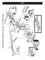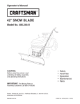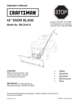
1
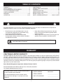
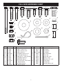
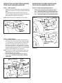
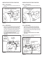
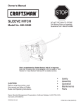
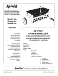
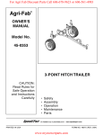
Operator's Manual ® 42" SNOW BLADE Model No. 486.244414 CAUTION: Before using this product, read and follow all Safety, Assembly and Operating Instructions IMPORTANT: For Missing Parts or Assembly Questions Call 866-576-8388 STOP DO NOT RETURN TO STORE For Missing Parts or Assembly Questions Call 1-866-576-8388 • • • • • Safety Assembly Operation Maintenance Parts Want more information or assembly tips? Scan for Video Instruction Guide. Sears Brands Management Corporation, Hoffman Estates, IL 60179 U.S.A. www.sears.com/craftsman PRINTED IN U.S.A. FORM NO. 41793 (12/15/14) TABLE OF CONTENTS WARRANTY..................................................................... 2 SAFETY RULES.............................................................. 2 ACCESSORIES AND ATTACHMENTS............................ 3 FULL SIZE HARDWARE CHART.................................... 3 CARTON CONTENTS..................................................... 4 ASSEMBLY................................................................. 5-13 OPERATION............................................................. 14-15 MAINTENANCE............................................................. 15 SERVICE AND ADJUSTMENTS....................................16 STORAGE.................................................................16 TROUBLESHOOTING...............................................17 REPAIR PARTS ILLUSTRATION......................................18 REPAIR PARTS LIST................................................19 PARTS ORDERING/SERVICE...............BACK COVER SAFETY Any power equipment can cause injury if operated improperly or if the user does not understand how to operate the equipment. Exercise caution at all times when using power equipment. • • Read the tractor and snow blade owner's manuals and know how to operate your tractor before using tractor with snow blade attachment. Never operate tractor and snow blade without wearing proper clothing suited to weather conditions and operation of controls. • • Never allow children to operate tractor and snow blade, and do not allow adults to operate without proper instructions. Always begin with transmission in first (low) gear and gradually increase speed as conditions permit. Look for this symbol to point out important safety precautions. It means — Attention!! Become alert!! Your safety is involved. WARRANTY CRAFTSMAN LIMITED WARRANTY FOR ONE YEAR from the date of sale this product is warranted against defects in material or workmanship. WITH PROOF OF SALE a defective product will be replaced free of charge. For warranty coverage details to obtain free replacement, visit the web page: www. craftsman.com/ warranty To obtain warranty coverage, return a defective product with proof of sale to the retailer from which it was purchased for free replacement. This warranty is void if this product is ever used while providing commercial services or if rented to another person. This warranty gives you specific legal rights, and you may also have other rights which vary from state to state. Sears Brands Management Corporation, Hoffman Estates, IL 60179 DO NOT RETURN TO STORE for Missing Parts or Assembly Questions Call 1-866-576-8388 Attachment Hotline The model number and serial numbers will be found on a decal attached to the snow blade. MODEL NUMBER: 486.244414 You should record both the serial number and the date of purchase and keep in a safe place for future reference. SERIAL NUMBER: __________________ DATE OF PURCHASE: __________________ 2 FULL SIZE HARDWARE CHART A B E D C F G H I O J P S N T K Q L R U W M V X REF. A B C D E F G H I J K L M Y PART NO. QTY. DESCRIPTION REF. PART NO. QTY. DESCRIPTION 46071 1 Hex Bolt, 1/4-20 x 3-1/4" N R19172410 8 1/2" Washer, (Large) 43648 1 Hex Bolt, 1/4-20 x 1-1/2" O 43070 6 3/8" Washer 43085 1 Hex Bolt, 5/16-18 x 1-1/2" P 43081 4 5/16" Washer 43001 14 Hex Bolt, 3/8-16 x 1" Q R19171616 1 1/2" Washer 710-0305 2 Carriage Bolt, 3/8-16 x 1-1/4" R 43003 6 3/8" Lock Washer 44326 6 Bolt, Carriage 5/16-18 x 1" S 44917 2 Palnut, 3/8" 47631 6 Hex Bolt, 3/8" x 1" (Thd. Forming) T 23658 1 Spacer, 5/8" Long 43350 6 Carriage Bolt, 3/8-16 x 1" U 46053 2 Spacer, 1" long 48106 2 Shoulder Bolt, 3/8 x .9" V 43010 2 Cotter Pin 1/8" x 1-1/4" 712-0256 2 Hex Jam Nut, 5/16" Fine Thread W 43055 4 Hairpin Cotter 47189 3 1/4" Nylock Hex Nut X 43082 2 Lock Nut, 3/8" 47810 7 5/16" Nylock Hex Nut Y 43407 2 Hex Bolt, 3/8-16 x 3/4" HA21362 18 3/8" Nylock Hex Nut 3 PARTS IN PACKAGES NOT SHOWN FULL SIZE 1 5 10 8 6 4 9 7 2 11 12 3 REF QTY PART NO DESCRIPTION 1 2 746-0260 Cable End Fitting 2 1 05762 Cable Mount Bracket 3 1 43348 Angle Lock Spring 4 2 726-0178 Nylon Tie 5 1 23856 Spring Mount Rod 6 1 46065 Channel Pivot Pin REF QTY PART NO DESCRIPTION 7 1 — Blade Adjust Spring 8 1 731-0869 Plastic Grip 9 1 62561 Grip Assembly 10 2 23151 Angle Lock Bars 11 1 46066 Blade Pivot Shaft 12 2 24690 Skid Shoe CARTON CONTENTS (Loose Parts in Carton) NOTE: Not all supplied parts will be needed for your tractor model. Unused parts may be discarded. 15 For model 917 tractors 13 18 17 14 16 21 For model 247 tractors 23 For model 247 tractors 24 19 25 26 22 20 REF QTY PART NO 13 1 27611 14 1 27612 15 1 24023 16 2 25647 17 1 — 18 1 — 19 1 48167 DESCRIPTION Hanger Bracket, L.H. (model 917) Hanger Bracket, R.H. (model 917) Pivot Support Bracket Angle Support Bracket Channel Assembly Blade Assembly Blade Pivot Rod REF QTY PART NO 20 1 — 21 1 63033 22 1 49808 23 2 24520 24 1 — 25 1 — 26 2 27864 4 DESCRIPTION Lift Handle Tube Lift Handle Rod Cable Slotted Angle Support Bracket Mounting Bracket, R.H. (model 247) Mounting Bracket, L.H. (model 247) Blade Mount Bracket (model 247) ASSEMBLY TOOLS REQUIRED FOR ASSEMBLY INSTRUCTIONS FOR 917 MODEL TRACTORS (1)Pliers (1)Hammer (1) Adjustable Wrench (or socket set) (1) 9/16" Open End or Box End Wrench (1) 7/16" Open End or Box End Wrench (1) 1/2" Open End or Box End Wrench LOCATE THE MOWER SUSPENSION BRACKETS NOTE: Not all of the supplied parts and hardware will be needed for any one particular tractor. Unneeded items may be discarded after assembly has been completed. NOTE: Right hand (RH) and left hand (LH) are determined from the operator's position while seated on the tractor. • If there is a single mower deck suspension bracket underneath the middle of the front axle as shown in figure 1 below, go to page 6 "INSTRUCTIONS FOR TRACTORS WITH SINGLE FRONT DECK SUSPENSION BRACKET". • If your tractor does not have a mower deck suspension bracket underneath the front axle, go to page 6 "INSTRUCTIONS FOR TRACTORS WITH DUAL FRONT SUSPENSION BRACKETS". CAUTION: Do not begin assembling until the tractor engine, muffler and exhaust deflector have been allowed to cool off. LOCATE MODEL LABEL OF TRACTOR • Look under your tractor seat, locate the serial number, and proceed to the step as shown. ® MODEL SERIAL 917. 000000 000000A000000 MOWER DECK SUSPENSION BRACKET 193653 917 MODEL TRACTORS STAY ON PAGE 5 FIGURE 1 ® MODEL SERIAL 247. 000000 000000A000000 193653 247 MODEL TRACTORS GO TO PAGE 8 (BOTTOM) 5 INSTRUCTIONS FOR TRACTORS WITH SINGLE FRONT DECK SUSPENSION BRACKET INSTRUCTIONS FOR TRACTORS WITH DUAL FRONT DECK SUSPENSION BRACKETS STEP 1: (SEE FIGURE 2) • Remove the tractor hood. Refer to your tractor owners manual for instructions on how to properly remove the hood. • Remove the browning shield from the front of the tractor as shown. Hold onto the shield as you remove the second bolt to prevent it from falling. IDENTIFY YOUR SUSPENSION BRACKETS • Compare your tractor to the ones shown in figure 4. • If your tractor resembles the top illustration, go to page 7 "INSTRUCTIONS FOR TYPE A TRACTORS". • If your tractor resembles the bottom illustration, go to page 7 "INSTRUCTIONS FOR TYPE B TRACTORS". TYPE A NOTE: Reinstall browning shield before using tractor. FRONT SUSPENSION BRACKET REMOVE BROWNING SHIELD TYPE B FIGURE 2 STEP 2: (SEE FIGURE 3) • Fasten the R.H. Side Plate (bend facing out) to the front three holes in the tractor frame using three 3/8" x 1" carriage bolts (H), three large 1/2" washers (N) (see note) and three 3/8" nylock nuts (M). For the rear hole, use a 5/16" x 1" carriage bolt (F), a large 1/2" washer (N) and a 5/16" nylock nut (L). Place the washers between the tractor frame and the side plate. Tighten all bolts. Repeat for L.H. side plate. NOTE: If there is an engine mounting plate (shown with dotted lines) leave the large 1/2" washer (N) off the bolt that goes through the plate. • Reinstall the browning shield removed in figure 2. • Go to page 8 "INSTRUCTIONS FOR 917 MODEL TRACTORS". 5/16" x 1" CARRIAGE BOLT (F) (SEE NOTE) FRONT SUSPENSION BRACKET FIGURE 4 ENGINE MOUNTING PLATE 5/16" NYLOCK NUT (L) 1/2" LARGE WASHER (N) 3/8" NYLOCK NUT (M) 3/8" x 1" CARRIAGE BOLT (H) FIGURE 3 6 INSTRUCTIONS FOR TYPE A TRACTORS INSTRUCTIONS FOR TYPE B TRACTORS STEP 1: (SEE FIGURE 5) STEP 1: (SEE FIGURE 7) • Remove any bolts found in the holes indicated in the illustration. • Remove any bolts found in the holes indicated in the illustration. REMOVE BOLTS FROM THESE HOLES REMOVE BOLTS FROM THESE HOLES FRONT SUSPENSION BRACKET FRONT SUSPENSION BRACKET FIGURE 5 FIGURE 7 STEP 2: (SEE FIGURE 6) • Attach the R.H. hanger bracket to the two front empty holes on the right side of the tractor frame using two new 3/8" x 1" hex bolts (D), 3/8" lock washers (R), and 3/8" flat washers (O) as shown. For the rear hole, use a 3/8" x 1" hex bolt (D), 3/8" lock washer (R) and 3/8" flat washer (O) with a large 1/2" washer (N) placed between the hanger bracket and the tractor frame. Tighten. Repeat for the left side. • Go to page 8 "INSTRUCTIONS FOR 917 MODEL TRACTORS". STEP 2: (SEE FIGURE 8) • Attach the R.H. hanger bracket to the three holes shown on the side of the tractor frame using three 3/8" x 1" hex bolts (D), 3/8" lock washers (R), 3/8" flat washers (O) and 1/2" large washers (N). Use 3/8" nylock nuts (M) on inside of frame if bolts insert freely into holes. Tighten. • Repeat for other side. • Go to page 8 "INSTRUCTIONS FOR 917 MODEL TRACTORS". 3/8" FLAT WASHER (O) 3/8" LOCK WASHER (R) NOTE: Use special 3/8" x 1" thread forming bolts (G) in any holes that are too small for regular bolts. 1/2" LARGE WASHER (N) 3/8" x 1" HEX BOLT (D) (OR THREAD FORMING BOLT (G) IF NEEDED) 3/8" x 1" HEX BOLT (D) 3/8" LOCK WASHER (R) 3/8" FLAT WASHER (O) R.H. HANGER BRACKET R.H. HANGER BRACKET FIGURE 6 FIGURE 8 7 3/8" NYLOCK NUT (M) (IF NEEDED) 1/2" LARGE WASHER (N) INSTRUCTIONS FOR 917 MODEL TRACTORS STEP 1: (SEE FIGURE 9) • Assemble one angle support bracket to the topmost set of holes in the hanger brackets using two 3/8" x 1" hex bolts (D) and 3/8" nylock nuts (M). Assemble the second angle support bracket to the second from the bottom set of holes in the hanger brackets using two 3/8" x 1" hex bolts (D) and 3/8" nylock nuts (M). Be sure the brackets are turned as shown. Do not tighten yet. STEP 2: (SEE FIGURE 10) • Assemble the pivot support bracket to the angle support brackets using four 3/8" x 1" hex bolts (D) and four 3/8" nylock nuts (M). Do not tighten yet. • Tighten the 4 bolts fastening the angle support brackets to the hanger brackets. • Tighten the 4 bolts fastening the pivot support bracket to the angle support brackets. • GO TO PAGE 10. 3/8" x 1" HEX BOLT (D) 3/8" x 1" HEX BOLT (D) 3/8" NYLOCK NUT (M) 3/8" NYLOCK NUT (M) PIVOT SUPPORT BRACKET ANGLE SUPPORT BRACKET FIGURE 9 FIGURE 10 INSTRUCTIONS FOR 247 MODEL TRACTORS STEP 1: (SEE FIGURE 11) • Attach an angle support bracket to the top holes in the quick attach brackets using two 3/8" x 1" hex bolts (D) and 3/8" nylock nuts (M). Do not tighten • Attach an angle support bracket to the bottom holes in the quick attach brackets using two /8" x 1" hex bolts (D) and 3/8" nylock nuts (M). Do not tighten. 3/8" x 1" HEX BOLT (D) BEND FACES IN FIGURE 11 STEP 2: (SEE FIGURE 12) • Assemble the pivot support bracket to the slotted angle support brackets using four 3/8" x 1" hex bolts (D) and four 3/8" nylock nuts (M). Do not tighten yet. • Tighten the 4 bolts fastening the slotted angle support brackets to the quick attach brackets. • Tighten the 4 bolts fastening the pivot support bracket to the slotted angle support brackets. • GO TO PAGE 9. BEND FACES OUT 3/8" x 1" HEX BOLT (D) 3/8" NYLOCK NUT (M) 3/8" NYLOCK NUT (M) FIGURE 12 8 PIVOT SUPPORT BRACKET INSTRUCTIONS FOR 247 MODEL TRACTORS STEP 4: (SEE FIGURE 14) • Pull out on the attachment pins on the hitch assembly and swing the top of the pins down away from the holes they were in. • Hook the hitch assembly onto the shoulder bolts in the sides of the tractor frame. • Align the holes in the hitch assembly with the holes in the tractor frame. Insert the attachment pins to lock the hitch assembly in place. • GO TO PAGE 10. STEP 3: (SEE FIGURE 13) • Select the illustration below which most closely resembles your tractor. • Assemble a shoulder bolt (I) and a 3/8" nylock nut (M) to the front of the tractor frame on each side, unless a shoulder bolt is already present. A ATTACHMENT PIN SHOULDER BOLT 3/8" NYLOCK NUT (M) SHOULDER BOLT (I) B FIGURE 14 3/8" NYLOCK NUT (M) SHOULDER BOLT (I) C 3/8" NYLOCK NUT (M) SHOULDER BOLT (I) D 3/8" HEX LOCK NUT 3/8" x 3/4" HEX BOLT BLADE MOUNTING BRACKET FIGURE 13 SHOULDER BOLT 9 BLADE ASSEMBLY FOR ALL TRACTORS STEP 3: (SEE FIGURE 17) • Using a hammer, assemble a 3/8" palnut (S) onto one end of the spring mount rod. Insert the other end of the spring mount rod through the pivot plate using the rear set of holes. Support the assembled end of the spring mount rod on a block of wood, and assemble the remaining palnut onto the other end of the rod. STEP 1: (SEE FIGURE 15) • Assemble the two angle lock bars together as shown in figure 6, so that all holes are aligned. Use one 3/8" x 1-1/4" carriage bolt (E) and one 3/8" nylock nut (M). Be sure to insert bolt from side indicated. Do not tighten at this time. • Hold the angle lock bars so that the square holes are at the top. Insert the straight hook end of the angle lock spring through the small middle hole in both angle lock bars. 3/8" PALNUT (S) SPRING MOUNT ROD 3/8" NYLOCK NUT (M) 3/8" x 1-1/4" CARRIAGE BOLT (E) PIVOT PLATE ANGLE LOCK BARS 3/8" PALNUT (S) ANGLE LOCK SPRING FIGURE 15 (Right Hand Side View) STEP 4: (SEE FIGURE 18) • Assemble a 3/8" x 1-1/4" carriage bolt (E) through the square hole in the cable mount bracket and through the square hole in the angle lock bars. (The carriage bolts should face in opposite directions.) Using pliers hold the cable mount bracket in position, angling down towards the L.H. hole in the channel as shown in figure 15. Secure with a 3/8" nylock nut (M). Tighten. Refer to the figure for the correct angle for the cable mount bracket. STEP 2: (SEE FIGURE 16) • Insert the round hook end of the angle lock spring up through the hole in the spring mount bracket. • Insert the angle lock bars down through the slot in the channel. Underneath the channel, place a 1" long spacer (U) on each side of the angle lock bars and insert a 1/4" x 3-1/4" bolt (A) through the channel, angle lock bars and the spacers. Secure the bolt with a 1/4" nylock nut (K). Tighten so that lock bars can pivot freely. • At this time tighten the 3/8" carriage bolt and hex nut previously assembled to angle lock bars. 3/8" x 1-1/4" CARRIAGE BOLT (E) NOTE: When the angle lock bars are pulled back in slot, the pivot plate should unlock and be free to pivot to the right or left position. PIVOT PLATE (Top View) FIGURE 17 ALIGN CABLE MOUNT BRACKET WITH L.H. HOLE ANGLE LOCK BARS SPRING MOUNT BRACKET CHANNEL 1/4" NYLOCK NUT (K) 1" SPACERS (U) FIGURE 16 3/8" NYLOCK NUT (M) ANGLE LOCK SPRING FIGURE 18 1/4" x 3-1/4" HEX BOLT (A) (Right Hand Side View) 10 FRONT (Right Hand Side View) STEP 5: (SEE FIGURE 19) • Assemble one 5/16" jam nut (J) approximately 3/4" onto threaded end of control cable that has no rubber cap or preassembled nuts. Assemble threaded cable end through round hole in cable mount bracket and secure with another 5/16" jam nut (J). Tighten. NOTE: Some adjustment of jam nuts may be required after blade assembly is completed. CABLE MOUNT BRACKET STEP 7: (SEE FIGURE 21) • To attach the blade to the channel assembly, align the notched holes in the pivot plate with the notched holes in the blade. Insert a 1/8" x 1-1/4" cotter pin (V) down through the hole at the bend in the blade pivot shaft. Spread the ends of the pin. From the left side insert the blade pivot shaft, bend facing top of blade, through the notched holes. Secure the shaft with another 1/8" x 1-1/4" cotter pin (V) through the end hole in the shaft. Spread the ends of the pin. • Remove the plastic cap and one 3/8" hex nut from the bolt in the blade adjust spring. Adjust the remaining 3/8" hex nut down approximately 1" onto the bolt threads. Hook the spring over the spring mount rod. Place the bolt up through the hole in the top edge of the blade and reassemble the other 3/8" hex nut to the bolt and tighten down against the top edge of the blade. Replace the plastic cap over the end of the bolt threads. 3/4" 5/16" JAM NUT (J) 5/16" JAM NUT (J) 1/8" x 1-1/4" COTTER PIN (V) CHANNEL ASSEMBLY FIGURE 19 3/8" HEX NUT (TOP) REAR (Left Hand Side View) BLADE PIVOT SHAFT STEP 6: (SEE FIGURE 20) • Assemble ball end of control cable up through hole in cable end fitting and pull until ball slips inside curled edge of fitting. If ball won't slip under edge of curl, it will need to be inserted through open end of curl. • Assemble 1/4" x 1-1/2" (B) hex bolt down through the cable end fitting, the 5/8" long spacer (T) and the left hand hole in the channel assembly. Secure with a 1/4" nylock nut (K). Tighten. NOTCHED HOLE FIGURE 21 1/4" x 1-1/2" HEX BOLT (B) CHANNEL ASSEMBLY HOLE FIGURE 20 BLADE ADJUST SPRING SPRING MOUNT PIVOT PLATE ROD 5/8" SPACER (T) 1/4" NYLOCK NUT (K) 3/8" HEX NUT (BOTTOM) BLADE NOTE: Make sure the cable mount bracket is aligned with the cable end fitting to prevent binding of cable. The other end of the control cable will be attached in a later step. CABLE END FITTING PLASTIC CAP REAR (Left Hand Side View) 11 1/8" x 1-1/4" COTTER PIN (V) (Right Hand Side View) STEP 8: (SEE FIGURE 22) • Assemble the large 1/2" washer (Q) onto the channel pivot pin. • Attach the channel assembly to the tractor by placing the end of the channel assembly up inside the pivot support bracket on the tractor. Align hole (a) in the channel assembly with the hole in the pivot support bracket. Insert the channel pivot pin through the aligned holes from the left side, and secure it with a hairpin cotter (W). STEP 10: (SEE FIGURE 24) • Remove the rubber cap and the first jam nut from the threaded end of the control cable and slide them onto the control cable wire. Adjust the second jam nut on the threads so that it is approximately 3/4" from end. Assemble threaded end of cable through the cable mount bracket and secure it with the first jam nut. Reinstall the rubber cap onto the threaded cable end. NOTE: Some adjustment of jam nuts may be required after blade assembly is completed. 1/2" WASHER (Q) CABLE MOUNT BRACKET CHANNEL PIVOT PIN JAM NUTS RUBBER CAP CHANNEL ASSEMBLY 3/4" CONTROL CABLE END HAIRPIN COTTER (W) HOLE (a) FIGURE 22 FIGURE 24 (Right Hand Side View) (Right Hand Side View) STEP 9: (SEE FIGURE 23) • From the left side, insert the welded end of the lift handle rod through the hole in the end of the channel assembly (Figure 18). Next, insert the lift link pin through the hole in the bracket that is welded to the lift handle rod. (The lift link is pre-assembled to the pivot support bracket). Secure the bracket with a hairpin cotter (W) inserted up through the lift link pin. • Apply a light coating of oil to the straight upper portion of the lift handle rod. Slide the lift handle tube onto the rod. STEP 11: (SEE FIGURE 25) • Assemble plastic grip onto lock release grip assembly. • Attach lock release grip assembly to lift handle tube using one 5/16" x 1-1/2" hex bolt (C) and one 5/16" nylock nut (L). Do not overtighten the nut. The grip assembly must pivot freely. • Assemble the ball end of the cable to a cable end fitting as you did to the other end of the cable. Secure the cable end fitting to the weld bolt on the lock release grip with a 1/4" nylock nut (K). Do not overtighten the lock nut. The cable fitting must pivot freely. 5/16" x 1-1/2" HEX BOLT (C) LIFT HANDLE TUBE 1/4" WELD BOLT CABLE END FITTING LIFT HANDLE ROD CABLE 1/4" NYLOCK NUT (K) PLASTIC GRIP 5/16" NYLOCK NUT (L) LONG PIN (LIFT LINK) LOCK RELEASE GRIP ASSEMBLY WELDED BRACKET HAIRPIN COTTER (W) FIGURE 23 (Left Hand Side View) FIGURE 25 12 CABLE CABLEEND END FITTING FITTING (Right Hand Side View) STEP 12: (SEE FIGURE 26) • Place the end of the blade pivot rod down through the blade pivot shaft. Attach the other end of the blade pivot rod to the lift handle tube. Secure both ends with a hairpin cotter (W). The holes for the hairpin cotters should be parallel to the ground. • Use the two plastic ties to hold the cable securely to the outside of the handle tube and away from the tractor to avoid direct heat from the tractor muffler. • Squeeze the grip assembly to check blade pivot. To adjust, see Service & Adjustments section on p. 16. STEP 13: (SEE FIGURE 27) • Pivot the blade to the center position and lower it to the ground. Place shims under the blade to create the amount of ground clearance you want. The more uneven the surface the more clearance you will need. • Attach the skid shoes to the blade using two 5/16" x 5/16" x 1" carriage bolts (F), 5/16" washers (P) and 5/16" nylock nuts (L). Tighten the bolts with the skid shoes resting on the ground, . PLASTIC TIES 5/16" NYLOCK NUT (L) HAIRPIN COTTER (W) BLADE PIVOT ROD 5/16" WASHER (P) 5/16" x 1" CARRIAGE BOLT (F) LIFT HANDLE TUBE SKID SHOE FIGURE 27 BLADE PIVOT SHAFT HAIRPIN COTTER (W) FIGURE 26 (Left Hand Side View) 13 (Left Hand Side View) OPERATION KNOW YOUR SNOW BLADE Read this owner's manual and safety rules before operating your snow blade. Compare the illustration below with your snow blade to familiarize yourself with the various controls and their locations. LIFT HANDLE TUBE LOCK RELEASE GRIP ASSEMBLY BLADE PIVOT ROD ANGLE LOCK BARS BLADE ADJUST SPRING LIFT HANDLE ROD BLADE SHOE CONTROL CABLE BLADE PIVOT SHAFT LOCK RELEASE GRIP ASS'Y. LIFT HANDLE TUBE BLADE PIVOT ROD ANGLE LOCK BARS BLADE ADJUST SPRING BLADE SHOE BLADE PIVOT SHAFT LIFT HANDLE ROD CONTROL CABLE Unlocks the blade to swivel to the right and left. Raises or lowers the blade and pivots blade to the right and left. Connects blade to handle tube. Pivots blade to the right and left. Locks the blade in either the right hand, left hand or straight ahead position. Holds blade in position but permits it to pivot forward to pass over an obstruction. Ground-contacting part of blade. Adjusts for adequate ground clearance of blade. Connects blade to channel assembly. Allows blade to pivot forward. Connects lift handle tube to channel assembly. Raises and lowers the blade. Connects the lock release lever to the angle lock bars. To Pivot the Blade HOW TO USE YOUR SNOW BLADE • To Raise or Lower the Snow Blade • Use the handle grip located on the end of the handle tube. To raise the blade, pull back while pushing down on the handle grip. To lower blade, pull back while lifting up on handle grip. PULL BACK AND LIFT UP TO LOWER BLADE Raise the blade to transport position. To unlock the blade, push the lock release grip down against the handle tube. To pivot the blade, keep the grip depressed and push forward or pull back on the handle tube, sliding it along the lift rod. Release the grip to lock the blade when it is in either the right hand, the left hand or the straight ahead position. LOCK RELEASE GRIP ASSEMBLY HANDLE TUBE HANDLE TUBE HANDLE GRIP LIFT ROD PULL BACK AND PUSH DOWN TO RAISE BLADE FIGURE 28 FIGURE 29 14 Wheel weights and tire chains must be used with your snow blade for traction. These accessories are available at your nearest Sears retail store. CAUTION: Carefully inspect the area to be worked before operating the snow blade. Avoid pipes, roots, curbs or other heavy obstructions. Using the Snow blade • • • • • Prepare the lawn tractor engine for cold weather using instructions furnished with the lawn tractor. Always begin with the transmission in first (low) gear and gradually increase speed as required. Do not repeatedly push snow in the same direction. This causes excessive build up with each successive pass. To reduce icing on the blade, allow the lawn tractor and blade to adjust to outdoor temperature before operating. For improved snow removal performance, coat the blade with automotive type paste wax. CAUTION: Know the terrain. Avoid exceptionally steep slopes or drop-offs which may be hidden by the snow. Never run the snow blade into heavy material at high speed. CAUTION: Always lower the blade to the ground before leaving the tractor. MAINTENANCE CUSTOMER RESPONSIBILITIES • Read and follow the maintenance schedule and the procedures listed in the maintenance section. e us se on ge ch h u eas tora a c s e e ea y s e for fter ver efor e E B A B MAINTENANCE SCHEDULE Fill in dates as you complete regular service. Check for loose fasteners Check for worn or damaged parts Clean Blade Lubricate Blade Service Dates X X X X X CHECK FOR LOOSE FASTENERS • During the operating season, check all bolts, nuts and hairpin cotters to be sure they are secure. LUBRICATE CHECK FOR WORN OR DAMAGED PARTS • During the operating season, check for worn and damaged parts. Replace or repair any that have excessive damage or wear. CLEAN BLADE • During the operating season, clean the blade off after each use. Touch up any bare metal with paint or apply a light coat of grease or rust preventive. LUBRICATE LUBRICATE BLADE • Lubricate all pivot points to help maintain proper operation of blade. Apply a light coating of oil to the straight upper portion of the lift handle rod. FIGURE 30 15 LUBRICATE SERVICE AND ADJUSTMENTS To Adjust the Blade Pivot Lock Mechanism To Adjust Blade Spring • • The tension of the blade adjust spring may be altered to permit the blade to tilt forward to bypass solid obstructions. To change the spring tension, adjust the nuts at upper end of the spring bolt. Standing in front of blade, turn the nuts counterclockwise to relieve tension and clockwise to increase tension. Refer to figure 21 on page 11. If the blade will not unlock and pivot, the angle lock bars are not disengaging from the slots in the pivot plate. To correct, adjust the 5/16" hex jam nuts to draw the end of the control cable back towards the cable mount bracket. The less the threaded end of the cable extends through the bracket, the more the angle lock bars can retract to disengage from the slots in the pivot plate. To Adjust Blade Shoes • The blade shoes at the ends of blade may be raised for close work on smooth surfaces or lowered to raise the blade to work on rough or uneven areas. Make sure both shoes are set evenly and that the nuts are tightened securely. CABLE MOUNT BRACKET CONTROL CABLE 5/16" HEX JAM NUT 5/16" HEX JAM NUT FIGURE 32 BLADE SHOE FIGURE 31 STORAGE Recommendations When Storing • • • • • When the snow blade is not being used, remove all dirt and rust and touch up with paint. Touch up bare metal with paint or apply a light coat of grease or rust preventive. Lubricate all pivot points and all points shown in figure 30, page 15 in the maintenance section. Store in a dry area, protected from weather. • • • To Remove Blade From Tractor • • Lower the blade to the ground with the blade in the center (straight ahead) position. Remove the hairpin cotter which fastens the blade pivot rod to the blade pivot shaft. See figure 26 on page 13. • 16 Remove the hairpin cotter which fastens the lift handle rod to the lift link pin. See figure 23, page 12. Remove the hairpin cotter from the channel pivot pin and remove the pivot pin from the channel assembly. See figure 22 on page 12. Remove the blade, the channel assembly and the lift handle assembly from the tractor. The brackets assembled to the tractor frame may be left in place. To remove the brackets assembled to the tractor frame (side plates and pivot support brackets) refer to the figures appropriate for your tractor on pages 6 and 7. If the side plates are removed from the tractor frame, be sure to reassemble any bolts that were removed from the frame. Refer to figure 5 on page 6 and figure 7 on page 7. TROUBLESHOOTING PROBLEM CAUSE CORRECTION Blade is difficult to raise. Lift mechanism is binding Lubricate pivot points as shown in figure 30 on page 15. Blade is difficult to pivot. Handle tube is binding on lift rod. Lubricate lift handle rod as instructed in figure 23 on page 12. Blade will not unlock to pivot. Lock mechanism is out of adjustment and is not disengaging. Refer to the Service and Adjustments section on page 16. ACCESSORIES AND ATTACHMENTS These and other accessories are recommended for use with your unit. Call 1-888-331-4569 to find out if they are available. If available, they may be purchased at most Craftsman outlets or by calling 1-888-331-4569. WHEEL WEIGHT TIRE CHAINS WEIGHT BRACKET FOR DRAW BAR 17 SNOW CAB 18 44 58 16 40 43 5 39 58 52 24 32 29 54 51,59 47 53 38 18 52 44 25 28 51 25 27 9 51 51 23 51 16 36 C 37 25 16 9 49 16 31 48 41 42 38 50 47 C A 25 A 16 B 11 12 13 56 48 10 16 57 61 34 14 67 OPTIONAL ACCESSORY 26 47 46 45 33 41 16 30 55 B 35 17 15 36 8 44 7 63 19 3 70 36 16 65 8 69 68 35 44 20 21 60 64 7 44 62 REPAIR PARTS FOR MODEL 486.244414 - 42" SNOW BLADE 44 66 4 22 1 2 5 4 PARTS 19 REF. 1 2 3 4 5 7 8 9 10 11 12 13 14 15 16 17 18 19 20 21 22 23 24 25 26 27 28 29 30 31 32 33 34 35 36 PART NO. 23114 23117 62980 43080 44326 43081 24690 25647 24347 43262 23131 1540-118 23958 23130 HA21362 46066 43070 R9466R 44071 43015 44074 49808 62561 43055 46053 63033 27612 27611 24023 48167 65519 23151 23856 44917 43010 QTY. 1 1 1 6 8 4 2 2 1 1 1 1 1 1 18 1 6 1 1 2 1 1 1 4 2 1 1 1 1 1 1 2 1 2 3 DESCRIPTION Blade 42" Wear Plate 42" Reinforcement Plate Assembly Bolt, Carriage 5/16-18 x 3/4" Bolt, Carriage 5/16-18 x 1" Washer, 5/16" Skid Shoe Bracket, Angle Support Push Channel Hex Lock Nut, 1/2-13 Thread Bolt, Special Pivot Washer, Flat 1/2" Plate, Pivot 7 Ga. Bracket, Spring Mt. Nylock Hex Nut, 3/8" Shaft, Blade Pivot Washer, 3/8" STD. Spring, Blade Adjust Hex Bolt, 3/8-16 x 3-1/2" Hex Nut, 3/8-16 Thread Plastic Cap Control Cable Assembly Release Grip Assembly Pin, Hairpin Small 3/32" Spacer, .28 ID x 1" Lift Handle Rod Assembly Hanger Bracket, R.H. Hanger Bracket, L.H. Pivot Support Bracket Rod, Blade Pivot Lift Handle Tube Assembly Angle Lock Bar Spring Mount Rod Palnut, 3/8" Cotter Pin 1/8" x 1-1/4" REF. 37 38 39 40 41 42 43 44 45 46 47 48 49 50 51 52 53 54 55 56 57 58 59 60 61 62 63 64 65 66 67 68 69 70 PART NO. 43348 746-0260 731-0869 46471 712-0256 23658 43085 47810 05762 43648 47189 710-0305 46065 63034 43001 43350 43003 726-0178 R19171616 46071 43349 R19172410 47631 27352 27353 24520 40005 732-3127 43659 48106 66586 43407 27864 43082 41793 QTY. 1 2 1 1 2 1 1 13 1 1 3 2 1 1 14 6 6 2 1 1 1 8 6 1 1 2 2 2 2 2 1 2 2 2 1 DESCRIPTION Angle Lock Spring Cable End Fitting Grip, Plastic Handle, Grip Hex Jam Nut, 5/16-24 Thread Spacer Hex Bolt, 5/16-18 x 1-1/2" Nylock Hex Nut, 5/16" Cable Mount Bracket Hex Bolt, 1/4-20 x 1-1/2" Nylock Hex Nut, 1/4" Carriage Bolt, 3/8-16 x 1-1/4" Channel Pivot Pin Lift Link Assembly Hex Bolt, 3/8-16 x 1" Carriage Bolt, 3/8-16 x 1" Lock Washer 3/8" Plastic Tie Washer Hex Bolt, 1/4-20 x 3-1/4" Lg. Gr 5 1/4" x 1" Spring Pin Washer, 1/2" (Large) Hex Bolt, 3/8" x 1" (Thd. Forming) Hitch Bracket (RH) Hitch Bracket (LH) Angle Support Bracket Attachment Pin Compression Spring Spring Pin, 3/16 x 1" Shoulder Bolt, 3/8-16 x .9" Rubber Blade Kit (not included) Hex Bolt, 3/8-16 x 3/4" Blade Mount Bracket Lock Nut, 3/8" Owners Manual REPAIR PARTS LIST FOR MODEL 486.244414 - 42" SNOW BLADE Product questions or problems? 1-888-331-4569 Customer Care Hot Line Get answers to questions, troubleshoot problems, order parts, or schedule repair service. Para respuestas a preguntas o problemas, y ordenar piezas o pedir servicio para la reparación de su equipo. To help us help you, register your product at www.craftsman.com/registration Para poderte ayudar mejor, registra tu producto en www.craftsman.com/registration Join the Craftsman Club today! Receive exclusive member benefits including special pricing and offers, project sharing, expert advice, and SHOP YOUR WAY REWARDS! Como miembro exclusivo, recibe diversos beneficios como ofertas, precios especiales, proyectos nuevos, consejos de expertos y nuestro programa de puntos SHOP YOUR WAY REWARDS! ® Registered Trademark / TM Trademark of KCD IP, LLC in the United States, or Sears Brands, LLC in other countries ® Marca Registrada / TM Marca de Fábrica de KCD IP, LLC en Estados Unidos, o Sears Brands, LLC in otros países