1
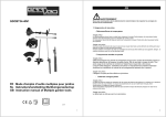
Owner's Manual/Manual Del Propietario
1/2 HP
GARAGE DOOR OPENER
ABRIDOR DE PUERTA DE COCHERA
For Residential Use Oniy/Sbio para uso residencial
Model/Modelo
139.53910
m
I11
o_
Z_
Read and follow all safety rules
and operating instructions before
first use of this product.
Leer y seguir todas ias regias de
seguridad y las instrucciones de
operacibn antes de usar este
producto por primera vez.
Fasten the manual near the garage
door after installation.
Guardar este manual cerca de la
puerta de la cochera.
Periodic checks of the opener are
required to ensure safe operation.
Se deben realizar revisiones
peribdicas del abridor de puertas
para asegurar su operacibn
segura.
Sears, Roebuck
and Co., Hoffman
www.sears.com/craftsman
Estates,
IL 60179 U.S.A
TABLE
OF CONTENTS
Introduction
2.7
Adjustment
27.29
Safety symbol and signal word review ........................ 2
Adjust the travel limits ...............................................
27
Preparing your garage door ........................................
Tools needed ...............................................................
Adjust the force .........................................................
28
Test the safety reversal system .................................
29
Test The Protector System ® ......................................
29
Planning ..................................................................
3
3
4-5
Carton inventory ..........................................................
6
Operation
Hardware inventory .....................................................
7
Operation safety instructions .....................................
Assembly
8-11
30.34
30
Using your garage door opener ................................ 30
Assemble the rail and install the trolley ...................... 8
Fasten the rail to the motor unit and
install the idler pulley ................................................... 9
install the chain/cable ................................................ 10
To open the door manually ........................................
Having a problem? ....................................................
33
Tighten the chain .......................................................
Diagnostic chart .........................................................
34
Installation
Using the walt-mounted Door Control ....................... 31
31
Care of your garage door opener .............................. 32
11
11.26
Programming
35-36
installation safety instructions .................................... 11
Determine the header bracket location ..................... 12
To add or reprogram a hand-held remote control .....35
To erase all codes ..................................................... 35
install the header bracket ..........................................
13
3-Function Remotes ..................................................
35
Attach the rail to the header bracket ......................... 14
To add, reprogram or change
a Keyless Entry PIN ..................................................
36
Position the opener ...................................................
15
Hang the opener .......................................................
install the door control ...............................................
16
17
Repair
Rail assembly parts ...................................................
37
install the light ...........................................................
18
installation parts ........................................................
37
Motor unit assembly parts .........................................
38
Attach the emergency release rope and handle ....... 18
Electrical requirements ..............................................
19
install The Protector System ®.............................. 20-22
Fasten the door bracket ....................................... 23-24
Connect the door arm to the trolley ..................... 25-26
Parts
37.38
Accessories
39
Warranty
39
Repair
Parts
and
Service
40
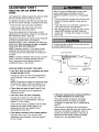
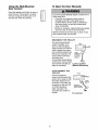
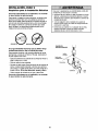
INTRODUCTION
Safety Symbol
and Signal Word Review
This garage door opener has been designed and tested to offer safe service provided it is installed, operated,
maintained and tested in strict accordance with the instructions and warnings contained in this manual.
When you see these Safety Symbols and Signal
Words on the following pages, they will alert you to
the possibility of serious injury or death if you do
not comply with the warnings that accompany them.
The hazard may come from something mechanical
or from electric shock. Read the warnings carefully.
Mechanical
Electrical
When you see this Signal Word on the following
pages, it will alert you to the possibility of damage to
your garage door and/or the garage door opener if
you do not comply with the cautionary statements
that accompany it. Read them carefully.
2
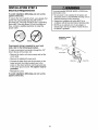
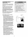
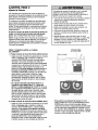
Preparing
your
garage
door
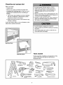
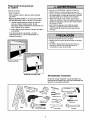
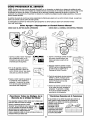
Before you begin:
• Disable locks
To prevent possibleSERIOUSINJURY or DEATH:
• ALWAYScall a trained door systems technician if
garage door binds, sticks, or is out of balance.An
unbalancedgarage door may not reverse when
required
• NEVERtry to loosen, move or adjust garage door, door
springs, cables, pulleys, brackets or their hardware, all
of which are under EXTREMEtension.
• Remove any ropes connected to garage door
• Complete the following test to make sure your
garage door is balanced and is not sticking or
binding:
1 Lift the door about halfway as shown. Release
the door. If balanced, it should stay in place,
supported entirely by its springs.
• Disable ALL locks and remove ALL ropes connected to
garage door BEFOREinstalling and operating garage
door opener to avoid entanglement.
2 Raise and lower the door to see if there is any
binding or sticking
If your door binds, sticks, or is out of balance, call a
trained door systems technician.
To prevent damage to garage door and opener:
• ALWAYSdisable locks BEFOREinstalling and operating
the opener.
• ONLYoperate garage door opener at 120V,60 Hz to
avoid malfunction and damage
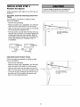
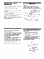
Sectional Door
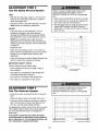
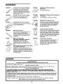
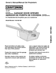
Tools
One-Piece Door
needed
During assembly, installation and adjustment of the
opener, instructions will call for hand tools as
illustrated below.
Pencil
Level (optionml)
Tape Measure
Hack Smw
Screwdriver
o)
Stepladder
Adjustable
3
End Wrench
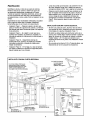
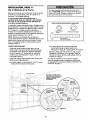
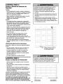
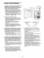
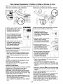
Planning
Identify the type and height of your garage door.
Survey your garage area to see if any of the
conditions below apply to your installation. Additional
materials may be required. You may find it helpful to
refer back to this page and the accompanying
illustrations as you proceed with the installation of
your opener.
Do you have an access door in addition to the
garage door? If not, Model 53702 Emergency Key
Release is required. See Accessories page.
Look at the garage door where it meets the floor.
Any gap between the floor and the bottom of the
door must not exceed 1/4" (6 mm). Otherwise, the
safety reversal system may not work properly. See
Adjustment Step 3. Floor or door should be
repaired.
Depending on your requirements, there are several
installation steps which may call for materials or
hardware not included in the carton.
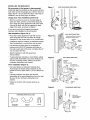
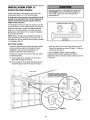
• Installation Step 1 - Look at the wall or ceiling
above the garage door. The header bracket must
be securely fastened to structural supports.
SECTIONAL DOOR INSTALLATIONS
Do you have a steel, aluminum, fiberglass or glass
panel door? If so, horizontal and vertical
reinforcement is required (Installation Step 11).
• Installation Step 5 - Do you have a finished ceiling
in your garage? If so, a support bracket and
additional fastening hardware may be required.
The opener should be installed above the center of
the door. If there is a torsion spring or center
bearing plate in the way of the header bracket, it
may be installed within 4 feet (1.22 m) to the left or
right of the door center. See Installation Steps 1
and 11.
• Installation Step 10 - Depending upon garage
construction, extension brackets or wood blocks
may be needed to install sensors.
• Installation Step 10 -Alternate floor mounting of
the safety reversing sensor will require hardware
not provided.
• If your door is more than 7 feet (2.13 m) high, see
rail extension kits listed on Accessories page.
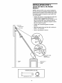
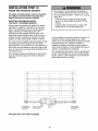
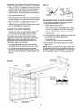
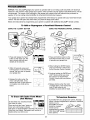
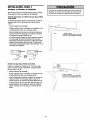
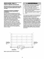
SECTIONAL DOOR INSTALLATION
FINISHED CEILING
fastening hardware
is required.
See page 16.
Horizontal and vertical reinforcement
is needed for lightweight garage doors
(fiberglass, steel, aluminum, door with
glass panels, etc.). See page 23 for details.
Slack in chain tension
is normal when
garage door is closed.
Header Wall
Motor unit
OR
f
Torsion Spring
WallDoor
Contro
Access Door
Header
Bracket
CLOSED POSITION
Trolley
Stop Bolt
Trolley
Garage
sOOn
P g
o
_m
_i_g
Gap between floor
and bottom of door
must not exceed 1/4" (6 mm).
Safety Reversing
Sensor
_
Door
Arm
Door
)or
4
Chain
Straig
°el
_id
}ader
all
_rage
g
2
Emergency
Release
_
Rope&
Handle
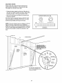
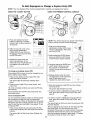
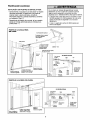
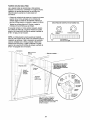
Planning
ONE-PIECE
(Continued)
DOOR INSTALLATIONS
Without a properly working safety reversal system,
persons (particularly small children) could be
SERIOUSLYINJUREDor KILLED by a closing garage
door.
• Generally, a one-piece door does not require
reinforcement. If your door is lightweight, refer to
the information relating to sectional doors in
Installation Step 11.
• The gap between the bottom of the garage door and
the floor MUST NOTexceed 1/4" (6 ram). Otherwise,
the safety reversal system may not work properly.
• The floor or the garage door MUST be repaired to
eliminate the gap.
• Depending on your door's construction, you may
need additional mounting hardware for the door
bracket (Step 11).
ONE-PIECE DOOR WITHOUT TRACK
FINISHED
CEILING
Support bracket
& fastening
hardware is required.
See page 16.
Rail
Slack in chain tension
is normal when garage
door is closed
Motor Unit
Wail-mounted
Door Control
CLOSED POSITION
Trolley Stop Bolt
cable
Trolley
Safety Reversing
Emergency
Release
Rope & Handle
Gap between floor
Sensor
and bottom of door must not exceed 1/4" (6 rnm).
Safety
Reversing
Sensor
eader
/atl
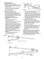
ONE-PIECE DOOR WITH TRACK
CLOSED
Trolley Stop Bolt
POSITION
Cable
Chain
Access I
Door
I
Header
Bracket
Cu_'ed
Door Ar
Rail
()1
Door
I
Bracket
_D
Safety
Reversing Sensor
Revel*sing
Gap between floor
Sensor
and bottom of door
must not exceed 1/4" (6 mm).
5
°°°°°°°©°
Garage
oct
Straight
Door
Arm
Eme_ency
Release
Rope &
Handle
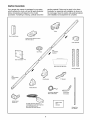
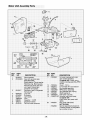
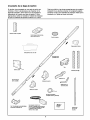
Carton
Inventory
Your garage door opener is packaged in one carton
which contains the motor unit and all parts illustrated
below. Accessories wilt depend on the model
purchased. If anything is missing, carefully check the
packing material. Parts may be stuck in the foam.
Hardware for assembly and installation is shown on
the next page. Save the carton and packing material
until installation and adjustment is complete.
Trolley
Door Control Button
Three*Function Remote Control
with Visor Clip (2)
Chain Spreader
Rail
CentedBack
Sections
Idler Pulley
H
Motor Unit with Light Lens
Hanging Brackets
Rraoln!(header)._
Y
"U" Bracket
Door Bracket
HeaderBracket
2-Conductor Bell Wire
White & White/Red
Safety Sensor
Bracket (2)
(2) Safety Reversing_
(1 Sending Eye and I Receiving
with 2-Conductor White &
White/Black Bell Wire attached
Curved Door
Arm Section
Safety Labels
and
Literature
Eye)
Straight Door
Arm Section
6
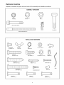
Hardware
Inventory
Separate all hardware and group as shown below for the assembly and installation procedures.
ASSEMBLY HARDWARE
©
@
Lock Nut
1/4"-20 (2)
©
Lock Washer
3/8" (1)
Nut
3/8" (1)
i
Bolt 1/4"-20x1-314"
(2)
Master
Link (2)
Trolley Threaded
INSTALLATION
Carriage Bolt
1/4"-20xl/2"
(2)
Wing Nut
1/4"-20 (2)
Idler Bolt (1)
Shaft (1)
HARDWARE
Ring
Fastener (3)
Nut 5/16"q8
Handle
(8)
©
Lag Screw
5/16"_9x1_5/8" (2)
Lag Screw
5/16"-18x1_7/8"
Hex Bolt
5/16"_18x7/8"
(4)
Screw
6ABxl-1/4"
(2)
LockWasher
(2)
5/16" (7)
Insulated
Staples (30)
Screw 6-32xl"
(2)
l
Rope
Carriage Bolt
5/16"q 8x2q/2"
Clevis Pin
5/16"x1-1/2"
(1)
(2)
Drywall Anchors (2)
Clevis Pin
5/16"x1" (1)
7
Spacer (2)
Clevis Pin
5/16"x1-1/4"
(1)
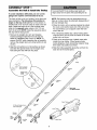
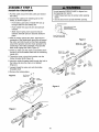
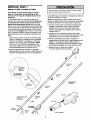
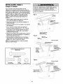
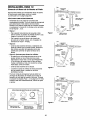
ASSEMBLY
Assemble
STEP
1
the Rail & Install
the
l_olley
To prevent INJURYfrom pinching, keep hands and
fingers away from the joints while assembling the rail.
To avoid installation difficulties, do not run the
garage door opener until instructed to do so.
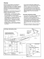
The front rail has a cut out "window" at the door end
(see illustration). The hole above this window is
larger on the top of the rail than on the bottom. A
smaller hole 3-1/2" (8.9 cm) away is close to the rail
edge. Rotate the back rail so it has a similar hole
close to the opposite edge, about 4-3/4" (12 cm)
from the far end. NOTE: Using the sequence above
the clips will be facing down.
NOTE: Rail sections may be assembled with the
clips up or down (down is preferred) disassembly of
rail may damage clips.
3. Place the motor unit on packing material to protect
the cover, and rest the back end of the rail on top.
For convenience, put a support under the front
end of the rail.
4. As a temporary trolley stop, clamp locking pliers
onto the rail 8" (20 cm) from the center of the idler
pulley hole, as shown.
1. Remove the straight door arm and hanging
bracket packaged inside the front rail and set
aside for Installation Step 5 and 12. NOTE: To
prevent INJURY while unpacking the rail carefully
remove the straight door arm stored within the rail
section.
5. Check to be sure there are 4 plastic wear pads
inside the inner trolley. If they became loose
during shipping, check all packing material. Snap
them back into position as shown.
2. Align the rail sections on a flat surface as shown
and slide the tapered ends into the larger ones.
Tabs along the side will lock into place.
6. Slide the trolley assembly along the rail from the
back end to the locked pliers.
Trolley
KEEP LARGER
HOLE ON TOP
Tapered
End
FRONT RAIL
(TOP)
Clip"
End
Tapered
End of
Rail
(TO MOTOR
End
Outer Trolley
8" (20 cm) Distance from
idler Pulley Hole
End
Inner Trolley
Tabs
Window
CutOut
\
Idler
Front Rail
(TO DOOR)
Wear Pads
8
UNIT)
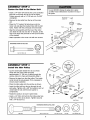
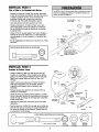
ASSEMBLY
Fasten
the
STEP
Rail
2
to the
Motor
Unit
To avoid SERIOUSdamage to garage door opener,
use ONLYthose bolts/fasteners mounted in the top of
the opener.
• Insert a 1/4"-20xl-3/4 bolt into the cover protection
bolt hole on the back end of the rail as shown.
Tighten securely with a 1/4"-20 lock nut. Do NOT
overtighten.
Hex Screws _==_o
8-32x7/16"
11I"
• Remove the two bolts from the top of the motor
unit.
I
I
I
i
I _
• Place the "U" bracket, flat side down onto the
motor unit and align the bracket hole with the bolt
holes. Fasten with the previously removed bolts.
Chain
Spreader
Bolts Motor Unit
_Sprecket
• Align the rail assembly with the top of the motor
unit. Slide the rail end onto the "U" bracket, all the
way to the stops that protrude on the top and sides
of the bracket.
"U" Bracket
Bolt
Cover
• Attach spreader to the motor unit with two screws.
HARDWARE
SHOWN ACTUAL
SIZE
©
Install
STEP
the Idler
Lock Nut
Lock Nut
1/4"-20
Bolt 1/4"-20x1-3/4
ASSEMBLY
SLIDE RAIL TO STOPS
ON TOP AND SIDES
OF BRACKET
Chain and
Cable
3
Pulley
• Lay the chain/cable beside the rail, as shown.
Grasp the end of the cable and pass
approximately 12" (30 cm) of cable through the
window. Allow it to hang until Assembly Step 5.
Trolley
• Remove the tape from the idler pulley. The inside
center should be pre-greased. If dry, regrease to
ensure proper operation.
Bolt
• Place the idler pulley into the window as shown.
Grease
Inside Pulley
• Insert the idler bolt from the top through the rail
and pulley. Tighten with a 3/8" lock washer and nut
underneath the rail until the lock washer is
compressed.
Idler
Lock
Washer
3/8"
Stop HOl,
I_1
• Rotate the pulley to be sure it spins freely.
Nut 3/8"
Pulley
Cable Link
/
I
• Insert a 1/4"-20xl-3/4 bolt into the trolley stop hole
in the front of the rail as shown. Tighten securely
with a 1/4"-20 lock nut.
HARDWARE
Idler Bolt
Trolley
Lock
_ut
Idler Pulley
SHOWN
Bolt 1/4"-20xl-3/4
9
ACTUAL
SIZE
Lock Nut 1/4"-20
Nut 3/8"
Lock Washer 3/8"
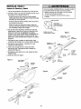
ASSEMBLY
Install
the
STEP
4
Chain/Cable
To avoid possible SERIOUSINJURYto fingers from
moving garage door opener:
• ALWAYSkeep hand clear of sprocket while operating
opener.
• Securely attach chain spreader BEFOREoperating.
1. Pull the cable around the idler pulley and toward
the trolley.
2. Connect the cable to the retaining slot on the
trolley, as shown (Figure 1):
• From below, push pins of master link bar up
through cable link and trolley slot.
Dispensing
Carton
Leave Chain and Cable
Inside Dispensing
• Push master link cap over pins and past pin
notches.
• Slide clip-on spring over cap and onto pin
notches until both pins are securely locked in
place.
to Prevent
Kinking.
Keep Chain and Cable
Taut When Dispensing
3. With the trolley against the pliers, dispense the
remainder of the cable/chain along the rail toward
the motor unit into the slot on the chain spreader,
around the sprocket onto the chain spreader and
continuing to the trolley assembly. The sprocket
teeth must engage the chain (Figure 2).
Figure 1
,i :
Clip-On Spring_
Master Link
_Link
oj
4. Check to make sure the chain is not twisted, then
connect it to the threaded shaft with the remaining
master link.
clip.on
Spri
5. Thread the inner nut and lock washer onto the
trolley threaded shaft (Figure 3).
Cable
Link
6. insert the trolley threaded shaft through the hole in
the trolley. Be sure the chain is not twisted
(Figure 4).
7. Loosely thread the outer nut onto the trolley
threaded shaft.
8. Remove the locking pliers.
Figure 2
: :
: ,
_
_
/
, ,
: ,
Trolley
Threaded
_
__
Shaft
"
Idler _,__
F
o,ey O
:
_ Sl-otted
Hole
Hole
:
,_
r
Chain
Spreader
"U" Bracket
:
MOtOrUnit
Figure 3
,eaded
Shaft
"
•J
Figure 4
Trolley
Threaded
Shaft
Round
Hole
lO
Lock
Washer
5/16"
Inner Nut
5/16"
P n
Notch
Master
Link Bar
'
:
Bolt
Cap
Master
RexScrews_
8-32x7/16"
Master
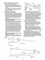
ASSEMBLY
Tighten
the
STEP
5
Chain
Figure I
• Spin the inner nut and lock washer down the
trolley threaded shaft, away from the trolley.
Trolley
Outer Lock
Nut
Washer
Threaded
Shaft
TO Tighten Outer Nut
• To tighten the chain, turn outer nut in the direction
shown (Figure 1).
• When the chain is approximately 1/4" (6 mm)
above the base of the rail at its midpoint, re-tighten
the inner nut to secure the adjustment.
TO Tighten
Inner Nut
Sprocket noise can result if chain is too loose.
Figure 2
When installation is complete, you may notice some
chain droop with the door closed. This is normal. If
the chain returns to the position shown in Figure 2
when the door is open, do not re-adjust the chain.
Chain
NOTE: During future maintenance, ALWAYS pull the
emergency release handle to disconnect trolley
before adjusting chain.
i
I
Base
of Rail
Mid!length
of Rail
NOTE: You may notice loosening of chain after
Adjustment Step 3 (Test the Safety Reversal
System). Check for proper tension and readjust
chain if necessar_ Then repeat Adjustment Step 3.
You have now finished assembling your garage
door opener. Please read the following warnings
before proceeding to the installation section.
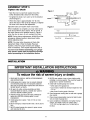
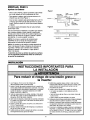
INSTALLATION
IMPORTANT INSTALLATION INSTRUCTIONS
To reduce the risk of severe injury or death:
1. READAND FOLLOWALL INSTALLATIONWARNINGS
AND INSTRUCTIONS.
8. NEVERwear watches, rings or loose clothing while
installing or servicing opener.They could be caught in
garage door or opener mechanisms.
9. Install wall-mounted garage door control:
• within sight of the garage door.
• out of reach of children at minimum height of 5 feet
2. Install garage door opener only on properly balanced
and lubricated garage door. An improperly balanced
door may not reverse when required and could result in
SEVEREINJURY or DEATH.
3. All repairs to cables, spring assemblies and other
hardware MUST be made by a trained door systems
technician BEFOREinstalling opener.
4. Disable all locks and remove all ropes connected to
garage door BEFOREinstalling opener to avoid
entanglement.
5. Install garage door opener 7 feet (2.13 m) or more
above floor.
(1.5m).
• away from all moving parts of the door.
10. Placeentrapment warning label on wall next to garage
door control.
11. Place manual release/safety reverse test label in plain
view on inside of garage door.
12. Upon completion of installation, test safety reversal
system. Door MUST reverse on contact with a
1-1/2" (3.8 cm) high object (or a 2x4 laid flat) on
the floor.
6. Mount emergency releasehandle 6 feet (1.83 m) above
floor.
7. NEVERconnect garage door opener to power source
until instructed to do so.
11
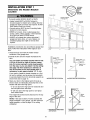
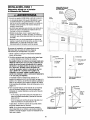
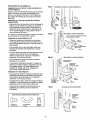
INSTALLATION
Determine
Location
the
STEP
Header
1
Ceilin
OPTIONAL
CEILING
g
Bracket
MOUNT
FOR
HEADER
BRACKET
Unfinishe_
Header Wall
Vertical Centerline
of Garage Door
To prevent possible SERIOUSINJURY or DEATH:
• Header bracket MUST be RIGIDLYfastened to
structural support on header wall or ceiling, otherwise
garage door might not reverse when required. DONOT
install header bracket over drywall.
• Concrete anchors MUST be used if mounting header
bracket or 2x4 into masonry.
• NEVERtry to loosen, move or adjust garage door,
springs, cables, pulleys, brackets, or their hardware,
all of which are under EXTREMEtension.
2x4
Structural
Suppods
• ALWAYScall a trained door systems technician if
garage door binds, sticks, or is out of balance. An
unbalanced garage door might not reverse when
required.
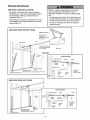
Installation procedures vary according to garage door
types. Follow the instructions which apply to your
door.
1. Close the door and mark the inside vertical
centerline of the garage door.
2. Extend the line onto the header wall above the
door.
"--'--2"
(5 cm) Track
Header Wal_
You can fasten the header bracket within 4 feet
(1.22 m) of the left or right of the door center
only if a torsion spring or center bearing plate
is in the way; or you can attach it to the ceiling
(see page 13) when clearance is minimal. (It
may be mounted on the wall upside down if
necessary, to gain approximately 1/2" (1 cm).
4eader Wall
of Travel
/f
Track
Highest Point
of Travel
Door
If you need to install the header bracket on a 2x4
(on wall or ceiling), use lag screws (not provided)
to securely fasten the 2x4 to structural supports as
shown here and on page 13.
Sectional
door with curved track
One-piece
door with horizontal
track
3. Open your door to the highest point of travel as
shown. Draw an intersecting horizontal line on the
header walt above the high point:
• 2" (5 cm) above the high point for sectional door
and one-piece door with track.
Header Wall
• 8" (20 cm) above the high point for one-piece
door without track.
_0 ci_)Header
Wall
This height wilt provide travel clearance for the top
edge of the door.
NOTE: If the total number of inches exceeds the
height available in your garage, use the maximum
height possible, or refer to page 13 for ceiling
installation.
Doer
__
_!igihl!;tel
Pivot
One-piece door without track:
jamb hardware
12
One-piece door without track:
pivot hardware
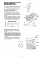
INSTALLATION
Install
the
STEP
Header
2
Wall Mount
Bracket
You can attach the header bracket either to the wall
above the garage door, or to the ceiling. Follow the
instructions which will work best for your particular
requirements. Do not install the header bracket
over drywall. If installing into masonry, use
concrete anchors (not provided).
Optional
Mounting
WALL HEADER BRACKET INSTALLATION
• Center the bracket on the vertical centerline with
the bottom edge of the bracket on the horizontal
line as shown (with the arrow pointing toward the
ceiling).
Holes
Ve_ical
Centerline
Door
Header
Wall
• Mark the vertical set of bracket holes (do not use
the holes designated for ceiling mount). Drill 3/16"
pilot holes and fasten the bracket securely to a
structural support with the hardware provided.
Lag Screws
5/16"x9x1-5/8"
2x4
Structural
Support
DoorSp#ng
f
/
HARDWARESHOWNACTUALSIZE
Horizontal
Line
/
/
/
Garage
Door
Highest Point of
Garage Door Travel
Lag Screw
5/16"-9xl-5/8"
CEILING HEADER BRACKET
Centetline
of Garage Door
INSTALLATION
• Extend the vertical centerline onto the ceiling as
shown.
• Center the bracket on the vertical mark, no more
than 6" (15 cm) from the walt. Make sure the arrow
is pointing away from the wall. The bracket can be
mounted flush against the ceiling when clearance
is minimal.
• Mark the side holes. Drill 3/16" pilot holes and
fasten bracket securely to a structural support with
the hardware provided.
Header
/
Bracket
6" (15 cm) Maximum
Ceiling
Mounting
Holes
Door
Spring
_J
Lag Screws
5/16"x9x1-5/8"
Header Wall
13
INSTALLATION
STEP 3
Attach the Rail to the Header
Bracket
NOTE: (Optional) With some existing installations,
you may re-use the old header bracket with the two
plastic spacers included in the hardware bag. Place
the spacers inside the bracket on each side of the
rail, as illustrated.
• Position the opener on the garage floor below the
header bracket. Use packing material as a
protective base. NOTE: If the door spring is in the
way you'll need help. Have someone hold the
opener securely on a temporary support to allow
the rail to clear the spring.
• Position the rail bracket against the header
bracket.
Header Bracket
• Align the bracket holes and join with a clevis pin
5/16"xl-1/2" as shown.
Idler Pulley
• Insert a ring fastener to secure.
0
Mounting
Hole
Header Bracket
0
Mounting
Hote
OPTION WITH SOME
EXISTING
INSTALLATIONS
Garage
Door
Opener Carton or
Suppod
HARDWARE
SHOWN
C
ACTUAL SIZE
0
Clevis Pin 5/16" x 1-1/2"
14
Ring fastener
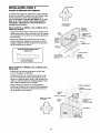
INSTALLATION
Position
the
STEP
4
Opener
To prevent damage to garage door, rest garage door
opener rail on 2x4 placed on top section of door.
Follow instructions which apply to your door type as
illustrated.
SECTIONAL DOOR OR ONE-PIECE DOOR WITH
TRACK
A 2x4 laid flat is convenient for setting an ideal
door-to-rail distance.
• Remove foam packaging.
Rail
• Raise the opener onto a stepladder. You will need
help at this point if the ladder is not tall enough.
• Open the door all the way and place a 2x4 laid flat
on the top section beneath the rail.
2x4 is used to determine
the correct mounting height
from ceiling.
• If the top section or panel hits the trolley when you
raise the door, pull down on the trolley release arm
to disconnect inner and outer sections. Slide the
outer trolley toward the motor unit. The trolley can
remain disconnected until Installation Step 12
is completed.
ENGAGED
ONE-PIECE DOOR WITHOUT TRACK
A 2x4 on its side is convenient for setting an ideal
door-to-rail distance.
• Remove foam packaging.
• Raise the opener onto a stepladder. You will need
help at this point if the ladder is not tall enough.
• Open the door all the way and place a 2x4 on its
side on the top section of the door beneath the rail.
• The top of the door should be level with the top of
the motor unit. Do not position the opener more
than 4" (10 cm) above this point.
the correct mounting
from ceiling.
_
15
height
2x4 is used to determine
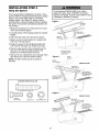
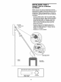
INSTALLATION
Hang
the
STEP
5
Opener
To avoid possible SERIOUSINJURYfrom a falling
garage door opener,fasten it SECURELYto structural
supports of the garage. Concrete anchors MUST be used
if installing any brackets into masonry.
Three representative installations are shown. Yours
may be different. Hanging brackets should be angled
(Figure 1) to provide rigid support. On finished
ceilings (Figure 2 and Figure 3), attach a sturdy
metal bracket to structural supports before installing
the opener. This bracket and fastening hardware are
not provided.
1. Measure the distance from each side of the motor
unit to the structural support.
Figure 1
/ Suppo_s
Lag Screws
5/16"-18xl-7/8"
2. Cut both pieces of the hanging bracket to required
lengths.
3. Drill 3/16" pilot holes in the structural supports.
Measure_
Distance
4. Attach one end of each bracket to a support with
5/16"-18xl -7/8" lag screws.
5. Fasten the opener to the hanging brackets with
5/16"-18x7/8" hex bolts, lock washers and nuts.
6. Check to make sure the rail is centered over the
door (or in line with the header bracket if the
bracket is not centered above the door).
Bolt 5/16"-18x7/6"
Lock Washer 5/16"
Nut 5/16"-16
7. Remove the 2x4. Operate the door manually. If the
door hits the rail, raise the header bracket.
Figure 2
NOTE: DO NOT connect power to opener at
this time.
Bracket
Hidden
z _ -
(Not Provided) _ _--""
__"
-
- _ _ .- _
FINISHED CEIUNG
Lag Screws
5/16"-18x
1-7/8"
%I%-/(Not Provided)
Bolt 5/! 6"-18x7/8"
r 5/16"
Nut 6/16"-18
Bott 5/16"- 18x7/8"
Lock Washer 5/16"
Nut 5/16"-18
HARDWARE
Hex Bolt
5/16"- 18x7/6"
SHOWN
ACTUAL SIZE
©©
Nut 5/16"q8
Figure 3
FINISHED
-" -- _ -- -_"
CEILING
Lock Washer 5/16"
X
,_
_
Oo _
Bott 5/16"-18x7/8"
°
Livou_k_/_sher 5/16 ....
16
_L_.,_-
_
_(NotProvided)
Lock Washer
Nut 5/16"-18
6/16"
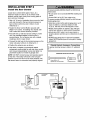
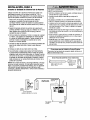
INSTALLATION
STEP
Install the Door Control
6
To prevent possible SERIOUSINJURY or DEATHfrom
electrocution:
Locate door control within sight of door, at a
minimum height of 5 feet (1.52 m) where small
children cannot reach, away from moving parts of
door and door hardware.
• Be sure power is not connected BEFOREinstalling door
control.
• Connect ONLYto 24 VOLTlow voltage wires.
To prevent possible SERIOUSINJURY or DEATHfrom a
closing garage door:
• Install door control within sight of garage door, out of
reach of children at a minimum height of 5 feet
1. Strip 1/4" (6 mm) of insulation from one end of bell
wire and connect to the two terminal screws on
back of door control by color: white to 2 and
white/red to 1.
• (1.52 m), and away from all moving parts of door.
NEVERpermit children to operate or play with door
control push buttons or remote control transmitters.
• Activate door ONLYwhen it can be seen clearly, is
properly adjusted, and there are no obstructions to door
travel.
2. Fasten the Door Control Button securely with
6ABx1-1/2" screws. If installing into drywall, drill
5/32" holes and use the anchors provided.
3. Run bell wire up walt and across ceiling to motor
unit. Use insulated staples to secure wire in
several places. Do not pierce wire with a staple,
creating a short or open circuit.
4. Connect the bell wire to the terminal screws on the
motor unit panel: white to 2; white/red to 1.
5. Position the antenna wire as shown.
• ALWAYSkeep garage door in sight until completely
closed. NEVERpermit anyone to cross path of closing
garage door.
Outside Keylock Accessory Connections
6. Use tacks or staples to permanently attach
entrapment warning label to wall near door control,
and manual release/safety reverse test label in a
prominent location on inside of garage door.
To lo.pener terminal screws: white to 2; white/red
HARDWARE
NOTE: DO NOT connect power and operate opener
at this time. The trolley will travel to the full open
position but will not return to the close position until
the sensor beam is connected and properly aligned.
Bell
(BACK VIEW)
BUTTON
Back Panel
of Opener
17
Door Control Button
Opener
Terminal Screws
Wire
DOOR CONTROL
SIZE
''''''''''''>
Lighted
2*Conductor
Bell Wire
Screws
Tern_inat
SHOWN ACTUAL
J
D_ywatl Anchors
n oated
Staples
INSTALLATION
Install
STEP
7
the Light
To prevent possible OVERHEATINGof the endpanel or
light socket,
• DONOT use short neck or specialty light bulbs.
• DONOT use halogen bulbs. Use ONLYincandescent.
• Install a 75 watt maximum light bulb in the socket.
The light will turn ON and remain lit for
approximately 4-1/2 minutes when power is
connected. Then the light will turn OFR
• Apply slight pressure on the sides of the lens and
slide the tabs into the slots in the end panel (See
illustration).
• To remove, reverse the procedure. Use care to
avoid snapping off lens tabs.
Light
Lens
• If the bulb burns out prematurely due to vibration,
replace with a Garage Door Opener bulb.
Guide
NOTE: Use only a standard light bulb. The use of a
short neck or speciality light bulb may overheat the
endpanel or light socket.
Lens
Slot
_"
75 Watt (Max)
Standard
Light Bulb
Lens
Tab
INSTALLATION
STEP
Attach the Emergency
Rope and Handle
8
Release
To prevent possible SERIOUSINJURYor DEATHfrom a
falling garage door:
• If possible, use emergency releasehandle to
disengage trolley ONLYwhen garage door is
CLOSED.Weak or broken springs or unbalanced
door could result in an open door falling rapidly
and/or unexpectedly.
• NEVERuse emergency releasehandle unless garage
doorway is clear of persons and obstructions.
NEVERuse handle to pull door open or closed. If rope
knot becomes untied, you could fall.
• Thread one end of the rope through the hole in the
top of the red handle so "NOTICE" reads right side
up as shown. Secure with an overhand knot at
least 1" (2.5 cm) from the end of the rope to
prevent slipping.
• Thread the other end of the rope through the hole
in the release arm of the outer trolley.
• Adjust rope length so the handle is 6 feet (1.83 m)
above the floor. Ensure that the rope and handle
clear the tops of all vehicles to avoid
entanglement. Secure with an overhand knot.
Trolley
NOTE: If it is necessary to cut the rope, heat seal
the cut end with a match or lighter to prevent
unraveling.
Enlergency
_
Release Handle
18
_)
_,
KOnVe[
band
INSTALLATION
Electrical
STEP
9
Requirements
To prevent possible SERIOUSINJURY or DEATHfrom
electrocution or fire:
To avoid installation difficulties, do not run the
opener at this time.
• Be sure poweris not connected to the opener,and
disconnect power to circuit BEFOREremoving cover to
establish permanent wiring connection.
• Garage door installation and wiring MUST be in
compliance with all local electrical and building codes.
• NEVERuse an extension cord, 2-wire adapter, or
change plug in any way to make it fit outlet. Be sure
the opener is grounded.
To reduce the risk of electric shock, your garage door
opener has a grounding type plug with a third
grounding pin. This plug will only fit into a grounding
type outlet. If the plug doesn't fit into the outlet you
have, contact a qualified electrician to install the
proper outlet.
PERMANENT WIRING
CONNECTION
RIGHT
Ground Tab
If permanent wiring is required by your local
code, refer to the following procedure.
Green
Ground Screw
To make a permanent connection through the 7/8"
hole in the top of the motor unit:
• Remove the motor unit cover screws and set the
cover aside.
Ground Wire
• Remove the attached 3-prong cord.
• Connect the black (line) wire to the screw on the
brass terminal; the white (neutral) wire to the
screw on the silver terminal; and the ground wire
to the green ground screw. The opener must be
grounded.
• Reinstall the cover.
To avoid installation difficulties, do not run the
opener at this time.
19
INSTALLATION
Install
The
STEP
Protector
10
System
_
• Be sure poweris not connected to the garage door
opener BEFOREinstalling the safety reversing sensor.
• To prevent SERIOUSINJURYor DEATHfrom a closing
garage door:
- Correctly connect and align the safety reversing
sensor. This required safety device MUST NOT be
disabled.
The safety reversing sensor must be connected
and aligned correctly before the garage door
opener will move in the down direction.
IMPORTANT INFORMATION ABOUT
THE SAFETY REVERSING SENSOR
- Install the safety reversing sensor so beam is NO
HIGHERthan 6" (15 cm) above garage floor.
When properly connected and aligned, the sensor
will detect an obstacle in the path of its electronic
beam. The sending eye (with an orange indicator
light) transmits an invisible light beam to the
receiving eye (with a green indicator light). If an
obstruction breaks the light beam while the door is
closing, the door will stop and reverse to full open
position, and the opener lights will flash 10 times.
If it is necessary to mount the units on the wall, the
brackets must be securely fastened to a solid
surface such as the wall framing. Extension brackets
(see accessories) are available if needed. If
installing in masonry construction, add a piece of
wood at each location to avoid drilling extra holes in
masonry if repositioning is necessary.
The units must be installed inside the garage so that
the sending and receiving eyes face each other
across the door, no more than 6" (15 cm) above the
floor. Either can be installed on the left or right of the
door as long as the sun never shines directly into the
receiving eye lens.
The invisible light beam path must be unobstructed.
No part of the garage door (or door tracks, springs,
hinges, rollers or other hardware) may interrupt the
beam while the door is closing.
The mounting brackets are designed to clip onto the
track of sectional garage doors without additional
hardware.
6" (15 crn) max.
above floor
Sensor Beam
6" (15 cm) max.
above f_oor
Protection Area
Facing the door from inside the garage
2O
INSTALLING THE BRACKETS
Figure 1
Be sure power to the opener is disconnected.
Install and align the brackets so the sensors will face
each other across the garage door, with the beam no
higher than 6" (15 cm) above the floor. They may be
installed in one of three ways, as follows.
Garage door track installation
DOORTRACKMOUNT
RIGHT SIDE)
Door
Track
Indicator
Light
(preferred):
• Slip the curved arms over the rounded edge of
each door track, with the curved arms facing the
door. Snap into place against the side of the track.
It should lie flush, with the lip hugging the back
edge of the track, as shown in Figure 1.
Bracket
Sensor
_
::_
If your door track wilt not support the bracket
securely, wall installation is recommended.
Wall installation (Figure 2 & 3):
WALL MOUNT (RIGHT SIDE)
• Place the bracket against the wall with curved
arms facing the door. Be sure there is enough
clearance for the sensor beam to be unobstructed.
Figure 2
Fasten Wood Block to Wall with
/Lag Screws (Not Provided)
Indicator
Light
• If additional depth is needed, an extension bracket
(See Accessories) or wood blocks can be used.
Sensor
Bracket
• Use bracket mounting holes as a template to
locate and drill (2) 3/16" diameter pilot holes on
the walt at each side of the door, no higher than 6"
(15 cm) above the floor.
• Attach brackets to wall with lag screws
(Not provided).
• if using extension brackets or wood blocks, adjust
right and left assemblies to the same distance out
from the mounting surface. Make sure all door
hardware obstructions are cleared.
Floor installation
Figure 3
WALL MOUNT (RIGHT
SIDE)
Extension
Bracket
(See Accessories)
(Figure 4):
(Provided with
Extension Bracket)
• Use wood blocks or extension brackets (See
Accessories) to elevate sensor brackets so the
lenses will be no higher than 6" (15 cm) above the
floor.
• Carefully measure and place right and left
assemblies at the same distance out from the wall.
Be sure all door hardware obstructions are
cleared.
• Fasten to the floor with concrete anchors as
shown.
SHOWN
ACTUAL
Indicator
Light
Lens
Figure 4
HARDWARE
SeRsor
Bracket
(Provided with
Extension
Bracket)
_"
FLOOR MOUNT (RIGHT
SIZE
i
;
Attach
ConcretewithAnchors
(Not Provided)
Indicator
Light
Carriage Bolt
1/4"-20xl/2"
Wing Nut
1/4"-20
SIDE)
Staples
J
21
MOUNTING AND WIRING THE SAFETY SENSORS
Figure 5
• Slide a 1/4"-20xl/2" carriage bolt head into the slot
on each sensor. Use wing nuts to fasten sensors to
brackets, with lenses pointing toward each other
across the door. Be sure the lens is not obstructed
by a bracket extension (Figure 5).
• Finger tighten the wing nuts.
• Run the wires from both sensors to the opener. Use
insulated staples to secure wire to wall and ceiling.
TROUBLESHOOTING
• Strip 1/4" (6 mm) of insulation from each set of
wires. Separate white and white/black wires
sufficiently to connect to the terminal screws: white
to 2 and white/black to 3 (Figure 6).
THE SAFETY SENSORS
1. If the sending eye indicator light does not glow
steadily after installation, check for:
• Electric power to the opener.
• A short in the white or white/black wires. These
can occur at staples, or at opener connections.
ALIGNING THE SAFETY SENSORS
• Plug in the opener. The indicator lights in both the
sending and receiving eyes will glow steadily if
wiring connections and alignment are correct.
• Incorrect wiring between sensors and opener.
• A broken wire.
2. If the sending eye indicator light glows steadily but
the receiving eye indicator light doesn't:
The sending eye orange indicator light will glow
regardless of alignment or obstruction. If the green
indicator light in the receiving eye is off, dim, or
flickering (and the invisible light beam path is not
obstructed), alignment is required.
• Check alignment.
• Check for an open wire to the receiving eye.
3. If the receiving eye indicator light is dim, realign
either sensor.
• Loosen the sending eye wing nut and readjust,
aiming directly at the receiving eye. Lock in place.
NOTE: When the invisible beam path is obstructed
or misaligned while the door is closing, the door will
reverse. If the door is already open, it will not close.
The opener lights will blink 10 times. See page 20.
• Loosen the receiving eye wing nut and adjust
sensor until it receives the sender's beam. When
the green indicator light glows steadily, tighten the
wing nut.
Connect Wire to
Terminal Screws
Figure 6
Bell Wire
Finished
Ceiling
/
Bell Wire
Sensor
Connections
DoorControl
Connections
(do_edline)
_
OPENER
Sensor_
\ Sensor
Invisible Light Beam
Protec_onArea
22
TERMINAL
SCREWS
INSTALLATION
Fasten
the
Door
STEP
11
Bracket
Fiberglass,aluminum or lightweight steel garage doors
Will. REQUIREreinforcement BEFOREinstallation of
door bracket. Contact your door manufacturer for
reinforcement kit.
Follow instructions which apply to your door type
as illustrated below or on the following page.
A horizontal reinforcement brace should be long
enough to be secured to two vertical supports. A
vertical reinforcement brace should cover the
height of the top panel.
HARDWARE
SHOWN ACTUAL
©
The illustration shows one piece of angle iron as the
horizontal brace. For the vertical brace, two pieces of
angle iron are used to create a U-shaped support
(Figure 1). The best solution is to check with your
garage door manufacturer for an opener installation
door reinforcement kit.
Nut 5/16"_18
NOTE: Many vertical brace installations provide for
direct attachment of the clevis pin and door arm. In
this case you will not need the door bracket; proceed
to Installation Step 12.
SIZE
©
LockWasher
5/16"
Carnage Bolt
5/16"_18x2-1/2"
SECTIONAL DOORS
• Center the door bracket on the previously marked
vertical centerline used for the header bracket
installation. Note correct UP placement, as
stamped inside the bracket (Figure 2).
• Position the bracket on the face of the door within
the following limits:
• Mark and drill 5/16" left and right fastening holes.
Secure the bracket as shown in Figure 1 if there is
vertical reinforcement.
If your installation doesn't require vertical
reinforcement but does need top and bottom
fastening holes for the door bracket, fasten as shown
in Figure 2.
A) The top edge of the bracket 2"-4" (5-10 cm)
below the top edge of the door.
B) The top edge of the bracket directly below any
structural support across the top of the door.
HeaderBracket
Horizontal and vertical reinforcement
is needed for lightweight garage doors
(fiberglass, aluminum, steel, doors with
Vertical
Figure 1
ure 2
23
ONE-PIECE DOORS
Please read and comply with the warnings and
reinforcement instructions on the previous page.
They apply to one-piece doors also.
• Center the door bracket on the top of the door, in
line with the header bracket as shown. Mark either
the left and right, or the top and bottom holes.
• Drill 5/16" pilot holes and fasten the bracket with
hardware supplied.
HARDWARE
SHOWN
ACTUAL
©
If the door has no exposed framing, drill 3/16" pilot
holes and fasten the bracket with 5/16"x1-1/2" lag
screws (not provided) to the top of the door.
Nut 5/16"-18
NOTE: The door bracket may be installed on the top
edge of the door if required for your installation.
(Refer to the dotted line optional placement drawing.)
Drill 3/16" pilot holes and substitute 5/16"xl- 1/2" lag
screws (not provided) to fasten the bracket to the
door.
Carriage Bolt
5/16"-18x2*f/2"
Header Wall
2x4
Finished Ceiling
Horizontal and vertical
reinforcement is needed for
doors
(fiberglass, aluminum, steel,
door with glass panel, etc.).
(Not Provided)
For a door with no exposed framing,
or for the optional installation, use
5/16"x1-f/2"
lag screws (Not Provided)
to fasten door bracket.
24
SIZE
©
LockWasher
5/f6"
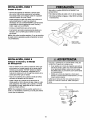
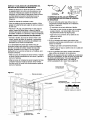
INSTALLATION
Connect
Door
STEP
Arm
12
Pulley
to Trolley
L.i
Trolley
Stop Bolt
SECTIONAL DOORS ONLY
• Make sure garage door is fully closed. Pull the
emergency release handle to disconnect the outer
trolley from the inner trolley. Slide the outer trolley
back (away from the pulley) about 8" (20 cm) as
shown in Figures 1, 2 and 3.
'
i
8" (20 cm) rain. -)1
Follow instructions which apply to your door type as
illustrated below and on the following page.
....
/
Inner
Ring
Fastener
/
Clevis Pin
5/t6"xt"
Tr°llr Y I _ii121
Emergency
Door
• Figure 1:
:
- Fasten straight door arm section to outer trolley
with the 5/16"xl" clevis pin. Secure the
connection with a ring fastener.
- Fasten curved section to the door bracket in the
same way, using the 5/16"xl-1/4" clevis pin.
Handle
Bracket
_
Clevis Pin
oLoLo_
¢_St j::
dIe
Door Arm
Curved Door Arm
5/t6°xt.i__
Figure 1
• Figure 2:
Pulley
- Bring arm sections together. Find two pairs of
holes that line up and join sections. Select holes
as far apart as possible to increase door arm
rigidity.
• Figure 3, Hole alignment
alternative:
- If holes in curved arm are above holes in straight
arm, disconnect straight arm. Cut about 6"
(15 cm) from the solid end. Reconnect to trolley
with cut end down as shown.
- Bring arm sections together.
- Find two pairs of holes that line up and join with
bolts, lock washers and nuts.
Bolts
5/t6"-t8x7/8"
• Pull the emergency release handle toward the
opener at a 45 ° angle so that the trolley release
arm is horizontal. Proceed to Adjustment Step 1,
page 27. Trolley wilt re-engage automatically when
opener is operated.
DoorBracket
Figure 2
Pulley
/ 4[..8" (20 cm) min...)i
HARDWARE
SHOWN ACTUAL
SIZE
%F
©©0
Nut 5/16"-18
C
Lock Washer 5/16"
°lC
Clevis Pin
5/16"x1" (Trolley)
Clevis Pin
5/16"x1-t/4"
Ring Fastener
P/
ol
(Door Bracket)
Hex Bolt
5/16"-18x7/8"
'
5%.t8x,,8.
Figure 3
25
ALL ONE-PIECE DOORS
1.Assemble
Door
Bracket
the door arm, Figure 4:
Fastener
• Fasten the straight and curved door arm sections
together to the longest possible length (with a 2
or 3 hole overlap).
Lock
Washers
5/16"
Clevis Pin
5/16"x1-1/4"
• With the door closed, connect the straight door
arm section to the door bracket with the
5/16"xl -1/4" clevis pin.
- Press the Door Control push button. The trolley
will travel to the fully closed position.
• On one-piece doors, before connecting the door
arm to the trolley, the travel limits must be
adjusted. Limit adjustment screws are located on
the left side panel as shown on page 27. Follow
adjustment procedures below.
- Manually close the door and lift the door arm to
the trolley. The arm should touch the trolley just
ahead of the door arm connector hole. Refer to
the fully closed trolley/door arm positions in the
illustration. If the arm is behind the connector
hole, adjust the limit further. One full turn equals
2" (5 cm) of trolley travel.
UP
- Turn the UP limit adjustment screw
counter-clockwise 4 turns.
3. Connect
the door arm to the trolley:
• Close the door and join the curved arm to the
connector hole in the trolley with the remaining
clevis pin. It may be necessary to lift the door
slightly to make the connection.
- Press the Door Control push button. The trolley
wilt travel to the fully open position.
- Manually raise the door to the open position
(parallel to the floor), and lift the door arm to the
trolley. The arm should touch the trolley just in
back of the door arm connector hole. Refer to
the fully open trolley/door arm positions in the
illustration. If the arm does not extend far
enough, adjust the limit further. One full turn
equals 2" (5 cm) of trolley travel.
• Secure with a ring fastener.
• Run the opener through a complete travel cycle.
If the door has a slight "backward" slant in full
open position as shown in the illustration,
decrease the UP limit until the door is parallel
to the floor.
NOTE: When setting the up limit on the following
page, the door should not have a "backward' slant
when fully open as illustrated below. A slight
backward slant will cause unnecessary bucking
and/or jerking operation as the door is being opened
or closed from the fully open position.
• Closed door adjustment: decrease DOWN
travel limit
- Turn the DOWN limit adjustment screw
clockwise 4 complete turns.
Figure 5
Cuwed
DoorArm
Figure 4
Figure 5:
• Open door adjustment: decrease
travel limit
Straight
Arm
Bolts
5/16"_18x7/8
• Secure with a ring fastener.
2. Adjustment procedures,
Nuts
5/16"-18
Inner Trolley
Outer Trolley
Emergency
Release Handle
Door Arm
Closed
Inner Trolley
Outer Trolley
± _.ii-]:
Backward Slant
Open Door
(Incorrect)
26
ADJUSTMENT
Adjust
Limits
the
UP and
STEP
DOWN
1
Travel
Without a properlyinstalled safety reversal system,
persons (particularly small children) could be
SERIOUSLYINJUREDor KILLED by a closing garage
door.
Limit adjustment settings regulate the points at which
the door wilt stop when moving up or down.
• Incorrect adjustment of garage door travel limits will
interfere with proper operation of safety reversal
system.
• If one control (force or travel limits) is adjusted, the
other control may also need adjustment.
• After ANY adjustments are made, the safety reversal
system MUST be tested. Door MUST reverse on
contact with 1-1/2" high (3.8 cm) object (or 2x4 laid
flat) on floor.
To operate the opener, press the Door Control push
bar. Run the opener through a complete travel cycle.
• Does the door open and close completely?
• Does the door stay closed and not reverse
unintentionally when fully closed?
If your door passes both of these tests, no limit
adjustments are necessary unless the reversing test
fails (Adjustment Step 3, page 29).
Adjustment procedures are outlined below. Read the
procedures carefully before proceeding to
Adjustment Step 2. Use a screwdriver to make limit
adjustments. Run the opener through a complete
travel cycle after each adjustment.
To prevent damageto vehicles, be sure fully open door
provides adequateclearance.
NOTE: Repeated operation of the opener during
adjustment procedures may cause the motor to
overheat and shut oft Simply wait 15 minutes and
try again.
Cover Protection
NOTE: If anything interferes with the door's upward
travel, it will stop. If anything interferes with the
door's downward travel (including binding or
unbalanced doors), it will reverse.
L
_
(5cm- I
t°cm) I
Bolt
_oo_
I
\
\
*
/
HOW AND WHEN TO ADJUST THE LIMITS
Left Side Panel
v
Limit Adjustment
Screws
• If the door does not open completely but opens
at least five feet (1.5 m):
Increase up travel. Turn the UP limit adjustment
screw clockwise. One turn equals 2" (5 cm) of
travel.
NOTE: To prevent the trolley from hitting the cover
protection bolt, keep a minimum distance of 2-4"
(5 cm - 10 cm) between the trolley and the bolt.
• If door does not open at least 5 feet (1.5 m):
Adjust the UP (open) force as explained in
Adjustment Step 2.
If the door reverses when closing and there is
no visible interference to travel cycle:
• If the door does not close completely:
Increase down travel. Turn the down limit
adjustment screw counterclockwise. One turn
equals 2" (5 cm) of travel.
If the opener lights are flashing, the Safety
Reversing Sensors are either not installed,
misalgned, or obstructed. See Troubleshooting,
page 22.
If door still won't close completely and the trolley
bumps into the pulley bracket (page 4), try
lengthening the door arm (page 25) and
decreasing the down limit.
Test the door for binding: Pull the emergency
release handle. Manually open and close the door.
If the door is binding or unbalanced, call for a
trained door systems technician. If the door is
balanced and not binding, adjust the DOWN
(close) force. See Adjustment Step 2.
• If the opener reverses in fully closed position:
Decrease down travel. Turn the down limit
adjustment screw clockwise. One turn equals 2"
(5 cm) of travel.
27
ADJUSTMENT
Adjust
STEP
2
the Force
Without a properly installed safety reversal system,
persons (particularly small children) could be
SERIOUSLYINJUREDor KILLED by a closing garage
door.
Force adjustment controls are located on the back
panel of the motor unit. Force adjustment settings
regulate the amount of power required to open and
close the door.
• Too much force on garage door will interfere with
proper operation of safety reversal system.
• NEVERincrease force beyond minimum amount
required to close garage door.
• NEVERuse force adjustments to compensate for a
binding or sticking garage door.
• If one control (force or travel limits) is adjusted, the
other control may also need adjustment.
• After ANY adjustments are made, the safety reversal
system MUST be tested. Door MUST reverse on
contact with 1-1/2" high (3.8 cm) object (or 2x4 laid
flat) on floor.
If the forces are set too light, door travel may be
interrupted by nuisance reversals in the down
direction and stops in the up direction. Weather
conditions can affect the door movement, so
occasional adjustment may be needed.
The maximum force adjustment range is about
3/4 of a complete turn. Do not force controls
beyond that point. Turn force adjustment controls
with a screwdriver.
NOTE: If anything interferes with the door's upward
travel, it will stop. If anything interferes with the
door's downward travel (including binding or
unbalanced doors), it will reverse.
HOW AND WHEN TO ADJUST THE FORCES
Force Adjustment
Controls
1. Test the DOWN (close) force
• Grasp the door bottom when the door is about
halfway through DOWN (close) travel. The door
should reverse. Reversal halfway through down
travel does not guarantee reversal on a 1-1/2"
(3.8 cm) obstruction. See Adjustment Step 3,
page 29. If the door is hard to hold or doesn't
reverse, DECREASE the DOWN (close) force by
turning the control counterclockwise. Make small
adjustments until the door reverses normally.
After each adjustment, run the opener through a
complete cycle.
Back panel
\
\l
• If the door reverses during the down (close)
cycle and the opener lights aren't flashing,
INCREASE DOWN (close) force by turning the
control clockwise. Make small adjustments until
the door completes a close cycle. After each
adjustment, run the opener through a complete
travel cycle. Do not increase the force beyond the
minimum amount required to close the door.
ADJUSTMENT
LABEL
2. Test the UP (open) force
• Grasp the door bottom when the door is about
halfway through UP (open) travel. The door
should stop. If the door is hard to hold or
doesn't stop, DECREASE UP (open) force by
turning the control counterclockwise. Make small
adjustments until the door stops easily and opens
fully. After each adjustment, run the opener
through a complete travel cycle.
Open Force
• If the door doesn't open at least 5 feet (1.5 m),
INCREASE UP (open) force by turning the
control clockwise. Make small adjustments until
door opens completely. Readjust the UP limit if
necessary. After each adjustment, run the opener
through a complete travel cycle.
28
Close Force
ADJUSTMENT
Test the Safety
STEP
3
Reversal
System
Without a properly installed safety reversal system,
persons (particularly small children) could be
SERIOUSLYINJUREDor KILLED by a closing garage
door.
TEST
• With the door fully open, place a 1-1/2" (3.8 cm)
board (or a 2x4 laid flat) on the floor, centered
under the garage door.
• Safety reversal system MUST be tested every month.
• If one control (force or travel limits) is adjusted, the
other control may also need adjustment.
• After ANY adjustments are made, the safety reversal
system MUST be tested. Door MUST reverse on
contact with 1-1/2" high (3.8 cm) object (or 2x4 laid
flat) on the floor.
• Operate the door in the down direction. The door
must reverse on striking the obstruction.
ADJUST
• If the door stops on the obstruction, it is not
traveling far enough in the down direction.
Increase the DOWN limit by turning the DOWN
limit adjustment screw counterclockwise 1/4 turn.
/,
_1 _&
NOTE: On a sectional door, make sure limit
adjustments do not force the door arm beyond a
straight up and down position. See the illustration
on page 25.
• Repeat the test.
• When the door reverses on the 1-1/2" (3.8 cm)
board, remove the obstruction and run the opener
through 3 or 4 complete travel cycles to test
adjustment.
J
• If the unit continues to fail the Safety Reverse Test,
call for a trained door systems technician.
IMPORTANT SAFETY CHECK:
Test the Safety Reverse System after:
• Each adjustment of door arm length, limits, or
force controls.
I 1/2 (38cm)board
(or a 2x4 laid fiat)
• Any repair to or adjustment of the garage door
(including springs and hardware).
• Any repair to or buckling of the garage floor.
• Any repair to or adjustment of the opener.
ADJUSTMENT
Test
The
Protector
STEP
Without a properly installed safety reversing sensor,
persons (particularly small children) could be
SERIOUSLYINJUREDor KILLED by a closing garage
door.
4
System
_
• Press the remote control push button to open the
door.
• Place the opener carton in the path of the door.
• Press the remote control push button to close the
door. The door will not move more than an inch
(2.5 cm), and the opener lights will flash.
The garage door opener will not close from a remote
if the indicator light in either sensor is off (alerting
you to the fact that the sensor is misaligned or
obstructed).
If the opener closes the door when the safety
reversing sensor is obstructed (and the sensors
are no more than 6" (15 cm) above the floor), call
for a trained door systems technician.
Safety Reversing Sensor
29
OPERATION
IMPORTANT
SAFETY INSTRUCTIONS
To reduce the risk of severe injury or death:
1. READAND FOLLOWALL WARNINGSAND
INSTRUCTIONS.
9. If one control (force or travel limits) is adjusted, the
other control may also need adjustment.
2. ALWAYSkeep remote controls out of reach of children.
NEVERpermit children to operate or play with garage
door control push buttons or remote controls.
3. ONLYactivate garage door when it can be seen clearly, it
is properly adjusted, and there are no obstructions to
door travel.
4. ALWAYSkeep garage door in sight until completely
closed. NO ONESHOULDCROSSTHE PATHOFTHE
MOVINGDOOR.
5. NO ONESHOULDGO UNDERA STOPPED,PARTIALLY
OPENEDDOOR.
6. If possible, use emergency release handle to disengage
trolley ONLYwhen garage door is CLOSED.Weak or
broken springs or unbalanced door could result in an
open door falling rapidly and/or unexpectedly.
7. NEVERuse emergency releasehandle unless garage
doorway is clear of persons and obstructions.
8. NEVERuse handle to pull garage door open or closed. If
rope knot becomes untied, you could fall.
Using
Your
Garage
Door
10. After ANY adjustments are made, the safety reversal
system MUST be tested.
11. Safety reversal system MUST be tested every month.
Garagedoor must reverse on contact with 1-1/2" high
(3.8 cm) object (or a 2x4 laid flat) on the floor.
12. ALWAYSKEEPGARAGEDOOR PROPERLYBALANCED
(see page 3). An improperly balanceddoor may not
reverse when required and could result in SEVERE
INJURYor DEATH.
13. All repairs to cables, spring assemblies and other
hardware, all of which are under EXTREMEtension,
MUST be made by a trained door systems technician.
14. ALWAYSdisconnect electric power to garage door
opener BEFOREmaking any repairs or removing
covers.
15.SAVETHESEINSTRUCTIONS.
6. If obstructed while opening, the door will stop.
7. If fully open, the door will not close when the beam
is broken. The sensor has no effect in the opening
cycle.
Opener
Your Security÷ ®opener and hand-held remote
control have been factory-set to a matching code
which changes with each use, randomly accessing
over 100 billion new codes. Your opener will operate
with up to eight Security4 ,_ remote controls and one
Security÷ ® Keyless Entry System. If you purchase a
new remote, or if you wish to deactivate any remote,
follow the instructions in the Programming section.
If the sensor is not installed, or is misaligned, the
door won't close from a hand-held remote. However,
you can close the door with the Door Control, the
Outdoor Key Switch, or Keyless Entry, if you activate
them until down travel is complete. If you release
them too soon, the door will reverse.
Activate your opener with any of the following:
• The hand-held Remote Control: Hold the large
push button down until the door starts to move.
• The wall-mounted Door Control: Hold the push
button or bar down until the door starts to move.
The opener lights will turn on under the following
conditions: when the opener is initially plugged in;
when power is restored after interruption; when the
opener is activated.
Lights will also turn on when someone walks through
the open garage door.
• The Keyless Entry (See Accessories): If provided
with your garage door opener, it must be
programmed before use. See Programming.
They will turn off automatically after 4-1/2 minutes.
Bulb size is 75 watts maximum.
When the opener is activated (with the safety
reversing sensor correctly installed and aligned)
1. If open, the door will close. If closed, it wilt open.
2. If closing, the door will reverse.
3. If opening, the door will stop.
4. If the door has been stopped in a partially open
position, it will close.
5. If obstructed while closing, the door will reverse, if
the obstruction interrupts the sensor beam, the
opener lights will blink for five seconds.
3O
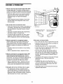
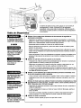
Using the Wall.Mounted
Door Control
Press the lighted push button to open or
close the door. Press again to reverse
the door during the closing cycle or to
stop the door while it's opening.
To Open
i_
I_]
ILl
I
I
I
the
Door
Manually
To prevent possible SERIOUSINJURYor DEATHfrom a
falling garage door:
• If possible, use emergency releasehandle to
disengage trolley ONLYwhen garage door is
CLOSED.Weak or broken springs or unbalanced
door could result in an open door falling rapidly
and/or unexpectedly.
• NEVERuse emergency releasehandle unless garage
doorway is clear of persons and obstructions.
NEVERuse handle to pull door open or closed. If rope
knot becomes untied, yOu could fall.
DISCONNECT
THE TROLLEY:
The door should be fully
closed if possible. Pull
down on the emergency
release handle (so that the
trolley release arm snaps
into a vertical position) and
lift the door manually. The
lockout feature prevents
the trolley from
reconnecting automatically,
and the door can be raised
and lowered manually as
often as necessary.
TO RE-CONNECT
TROLLE_
mrOll6j
Release Arm
In Manual
Disconnect
Positiont
Lockout position
(Manual disconnectl
THE
Trolle_
Pull the emergency
release handle toward the
opener at an angle so that
the trolley release arm is
horizontal. The trolley will
reconnect on the next UP
or DOWN operation.
either manually or by
Emergency
using the door control or
remote.
To reconnect
31
_,F_
CARE
OF YOUR
THE REMOTE CONTROL BATTERY
OPENER
LIMIT AND FORCE ADJUSTMENTS:
Weather conditions may
FORCE
CONTROLS
in door operation requiring
some re-adjustments,
cause some minor changes
particularly during the first
year of operation.
_
,!f battery is swallowed, immediately notify doctor.
Pages 27 and 28 refer to the LIMITCONTROLS
limit and force adjustments,
z\
,= =,
z\
Only a screwdriver is
_
Q '_ _r (_)
requ red. Fo ow the
"
_
instructions carefully.
Openthisend
firstt?avoidJ
crackmg
use
housing g _J
the
visor
chp
or
screwdriver blade to pry open
the case as shownl Insert
Repeat the safety reverse test (Adjustment
Step 3, page 29) after any adjustment of limits or
force.
MAINTENANCE
Z
Z Z Z
The lithium battery should
produce power for up to
5 years. To
replace
battery,
•
.
_
C_
"
battery positive side up (+).
Dispose of old battery properly.
SCHEDULE
1
NOTICE: To comply with FCC and or h]dusti_ Canada rules ([C), adjustment or [
modifications of this receiver and/or transmitter are prohibited, exceptfor changing the
cede setting or r_pl_cg_g
the battery.THEREARENO OTHERUSERSERVICEABLEPARTS.
Testedto
Comply
FCCStandards
OFFICEUSE.Operation
is subject
to
the following
twowith
co_]ditiong:(f)
thisFORNOMEOR
device may _]otcause
harmful int_fere_]ce,
a_d
Once a Month
• Manually operate door. If it is unbalanced or
binding, call a trained door systems technician.
(2) this device must _ccept any intederence received, including interference that may
cause undes _edopela ion.
• Check to be sure door opens & closes fully. Adjust
limits and/or force if necessary. (See pages 27
and 28)
• Repeat the safety reverse test. Make any
necessary adjustments. (See Adjustment Step 3)
Twice a Year
• Check chain tension. Disconnect trolley first. Adjust
if necessary. (See page 11)
Once a Year
• Oil door rollers, bearings and hinges. The opener
does not require additional lubrication. Do not
grease the door tracks.
32
HAVING
A PROBLEM?
1. My door will not close
on my motor unit: The
must be connected and
garage door opener will
and the light bulbs blink
safety reversing sensor
aligned correctly before the
move in the down direction.
• Verify the safety sensors are properly installed
aligned and free of any obstructions. Refer to
Installation Step 10: Install The Protector
System _.
• Check diagnostic LED for flashes on the motor
unit then refer to the Diagnostic Chart on the
following page.
2. My remotes will not activate the door:
• Verify your Premium door control is not blinking. If
it is blinking, deactivate the Lock Mode following
the instructions for Using the Premium Control
Console.
SafetySensor
Sending Eye Safety Sensor
(Amber Indicator Light)
• Reprogram remotes following the programming
instructions. Refer to Programming.
Receiving Eye Safety Sensor
(Green Indicator Light)
/
• If remote will still not activate your door. check
diagnostic LED for flashes on motor unit then
refer to Diagnostic Chart on the following page.
3. My door reverses for no apparent reason:
Repeat safety reverse test after adjustments to
force or travel limits. The need for occasional
6. My motor unit hums briefly:
• First verify that the trolley is against the stop bolt.
adjustment for the force and limit settings is normal.
Weather conditions in particular can affect door
travel.
• Release the door from the opener by pulling the
Emergency Release Rope.
• Manually bring the door to a closed position.
• Manually check door for balance or any binding
problems.
, Loosen the chain by adjusting the outer nut 4 to
5 turns. This relieves the tension.
• Refer to Adjustment Step 2, Adjust the Force.
• Run the motor unit from the remote control or
door control. The trolley should travel towards
the door and stop. If the trolley re-engages with
the door, pull the Emergency Release Rope to
disengage.
4. My door reverses for no apparent reason after
fully closing and touching the floor: Repeat
safety reverse test after adjustments to force or
travel limits. The need for occasional adjustment for
the force and limit settings is normal. Weather
conditions in particular can affect door travel.
, Decrease the UP travel by turning the UP Travel
adjustment screw 2 fu!l turns away from
the arrow.
• Re-tighten the outer nut so the chain is a
1/4" (6 mm) above the base of the rail. (When
the door is reconnected and closed, the chain
will sag. This is normal,)
• Refer to Adjustment Step 1, Adjust the UP and
DOWN Travel Limits. Decrease down travel by
turning down limit adjustment screw clockwise.
• If the trolley does not move away from the bolt,
repeat the steps above.
5. My lights will not turn off when door is open:
• The garage door opener is equipped with a
security light feature. This feature activates the
light on when the safety sensor beam has been
obstructed Refer to Operation section; Using the
Wall Mounted Door Control Light Feature
33
Bell Wire
Safe_
Your garage door opener is programmed with
self-diagnostic capabilities. The "Learn" button/diagnostic
LED will flash a number of times then pause signifying it
has found a potential issue. Consult Diagnostic Chart below.
Sensor
Diagnostic
Chart
Safety sensors wire open
(broken or disconnected).
OR
"-0 Symptom: One or both of the Indicator lights on the safety sensors do
not glow steady.
• Inspect sensor wires for a short (staple in wire), correct wiring polarity
/black/white wires reversed'L broken or disconnected wires, replace/attach
as needed.
• Disconnect all wires from back of motor unit
• Remove sensors from brackets and shorten sensor wires to 1-2 fl (30-60 cm;
from back each of sensor.
• Reattach sending eye to motor unit using shortened wires. If sending eye
indicator light glows steadily, attach the receiving eye.
• Align sensors if the indicator lights glow replace the wires for the sensors. If
the sensor indicator lights do not light, replace the safety sensors
Safety sensors w=re
shorted or black/white
wire reversed
-0
Door control
wire shorted.
or
Safety Sensors
slightly misaligned
(dim or flashing LED).
Symptom: LED is not lit on door control
• Inspect door control/wires for a short (staple in wire), replace as needed.
• Disconnect wires at door control, touch wires together. If motor unit activates.
replace door control.
• If motor unit does not activate, disconnect door control wires from motor unit.
Momentarily short across red and white terminals with jumper wire. If motor
unit activates replace door control wires.
_ymptom: Sending indicator light glows steadily, receiving indicator light
is dim or flashing.
• Realign receiving eye sensor, clean lens and secure brackets.
• Verify door track is firmly secured to wall and does not move.
| == Symptom: Motor has overheated; the motor unit does not operate or
..............
T"'w trolley is stuck on stop bolt = Motor unit hums briefly; RPM Sensor =
Short travel 6-8" (15-20 cm).
Motor overheated or
• Unplug unit to reset. Try to operate motor unit, check diagnostic code.
possible RPM sensor
• If it is still flashing 5 times and motor unit moves 6-8" (15-20 cm), replace RPM
failure. Unplug to reset.
sensor.
• If motor unit doesn't operate, motor unit is overheated. Wait 30 minutes and
retry. If motor unit still wilt not operate replace logic board.
Motor Circuit Failure.
Replace Receiver
Logic Board.
)tom: Motor unit doesn't operate.
• Replace logic board because motor rarely fails.
34
PROGRAMMING
NOTICE: If this Security,l_ garage door opener is operated with a non-rolling code transmitter, the technical
measure in the receiver of the garage door opene_ which provides security against code-theft devices, will be
circumvented. The owner of the copyright in the garage door opener does not authorize the purchaser or
supplier of the non-rolling code transmitter to circumvent that technical measure.
Your garage door opener has already been programmed at the factory to operate with your hand-held remote
control. The door will open and close when you press the large push button.
Below are instructions for programming your opener to operate with additional Security÷ _ remote controls.
To Add
USING THE "LEARN"
or Reprogram
a Hand.held
BUTTON
1. Press and hold the button on the
hand-held remote* that you wish
to operate your garage door.
2. While holding [he ENTER 3utton.
press and hold the LIGHT button
on the Premium Control Console.
2. Within 30 seconds press and
hold the button on the hand-held
remote* that you wish to operate
your garage door.
3,
3. Release the button when the
motor unit lights blink. It has
learned the code. If light bulbs are
not installed. [wo clicks will be
heard
Erase All
Unit
Codes From
Memory
Control
USING THE PREMIUM CONTROL CONSOLE
1. Press and release the "learn"
button on the motor unit. The
learn indicator light will glow
steadily for 30 seconds.
To
Remote
4,
Motor
Continue holding [he ENTER and
LIGHT buttons while you press
the push bar on the Premium
Control Console (all three buttons
are heldL
Release buttons when the motor
unit lights blink. It has learned the
code. If light bulbs are not
installed, two clicks will be heard.
*3.Function
Remotes
If provided with your garage door opener, the large
button is factory programmed to operate it. Additional
buttons on any
Security÷ _ 3-Function
_
remote or compact
_'_
remote Can be
_
_
programmed to operate
_
__
other Security.l._garage
___
door openers.
To deactivate any unwanted remote,
first erase all codes:
Press and hold the "learn" button on
motor unit until the learn indicator
light goes out (approximately 6 seconds). All previous
codes are now erased. Reprogram each remote or
keyless entry you wish to use.
35
To Add,
Reprogram
or
Change
a Keyless
Entry
PIN
NOTE: Your new Keyless Entry must be programmed to operate your garage door opener.
USING THE "LEARN"
BUTTON
USING THE PREMIUM CONTROL CONSOLE
[]
1. Press and release the "learn"
button on motor unit. The learn
indicator light will glow steadily for
30 seconds.
[]
[]
NOTE: This method requires two people if the Keyless
Entry is already mounted outside the garage.
1. Enter a four digit personal
identification number (PIN) of your
choice on the keypad. Then press
and hold ENTER.
2. Within 30 seconds enter a four
digit personal identification
number (PIN) of your choice on
the keypad. Then press and hold
the ENTER button.
2. While holding the ENTER button,
press and hold the LIGHT button
on the Premium Control Console.
3. Release the button when the
motor unit lights blink. It has
learned the code. If light bulbs are
not installed, two clicks will be
heard.
To change an existing,
3. Continue holding the ENTER and
LIGHT buttons while you press
the push bar on the Premium
Control Console (all three button s
are held).
known PIN
if the existing PIN is known, it may be changed by one
person without using a ladder.
1. Press the four buttons for the present PIN. then
press and hold the # butter
4, Release buttons when the motor
unit lights blink. It has learned the
code. If light bulbs are net
installed, two clicks will be heard.
The opener light will blink twice. Release the #
button.
2. Press the new4-digit PIN you have chosen. Lhen
press Enter.
The motor unitlightswill
_eenlearned.
2. Press the temporary 4-digit PIN you have chosen,
then press Enter.
The opener light will blink four times.
blink once when the PIN has
3. To set the number of hours this temporary PIN will
work, press the number of hours (up to 255), then
press _.
OR
Test by pressing the new PIN. then press Enter. The
door should move.
To set a temporary
PIN
You may authorize access by visitors or service people
with a temporary 4-digit PIN. After a programmed
qumber of hours or number of accesses, this temporary
PIN expires and will no longer open the door. It can be
used to close the door even after it has expired. To set
a temporary PIN:
1. Press the four buttons for your personal entry PIN
(nat the last temporary PIN), then press and hold the
butter
3, To set the number of times this temporary PIN will
work, press the number of times (up to 255), then
press #.
The opener light will blink once when the temporary PIN
has been Jearned.
Test by pressing the four buttons for the temporary PIN,
then press Enter. The door should move. If the
temporary PIN was set to a certain number of openings,
remember that the test has used up one opening.To
clear the temporary password, repeat steps 1-3, setting
the number of hours or times to 0 in step 3,
The opener light will blink three times. Release the
button.
36
REPAIR
Rail
PARTS
Assembly
Parts
5
KEY
NO.
1
4A1008
Master link kit
41C5141-1
Complete trolie
3
4
5
41A5665
144C56
41A5807
Complete rail
Idler pulley
Chain and cable
6
12D598-1
"U" bracket
NOT SHOWN
183A163
Wear pads
Rail clip
Parts
KEY
NO.
I
DESCRIPTION
2
41A145
Installation
PART
NO.
.
2
PART
NO.
1
2
3
41A4166
10A20
41A5076
4
5
29B137
41A2828
DESCRIPTION
Lighted door control button
3V 2032 Lithium battery
3-Function remote control case
(no circuit board_
Visor clip
Emergency release rope and handle
assembly
Header bracket w/clevis pin & fastener
2-Conductor bell wire: white & white/red
Door bracket w/clevis pin & fastener
Curved door arm section
Safety sensor kit: receiwng and
sending eyes with 3' 2-conductor bell
wire attached
6
7
8
9
10
41A5047
41B4494-1
41A5047-2
178B35
41A5034
11
12
13
41A5266-1
178B34
12B350
Safety sensor bracket
Straight door arm section
Hanging brackets
NOT SHOWN
41A5258-10
Assembly & Installation hardware bag
(see page 7_
Owner s manual
114A2848
1
37
MotorUnitAs_mblyPa_s
iiiiiiiiiiiiiiiiiiiiiiiiiiiiiiiiiiiiiiiiiiiiiiiiiiiiiiiiiiiiiiiiiiiiiiiiiiiiiiiiiiiiiiiiiiiiiiiiiiiiiiiiiiiiiiiiN_T8H_Niiiiiiiiiiiiiiiiiiiiiiiiiiiiii
iiiiiiiiiiiiiiiiiiiiiiiiiiiiiiiiiiiiiiiiiiiiiiiiiiiiiiiiiiiiiiiiiiiiiiiiiiiiiiiiiiiiiiiiiiiiiiiiiiiiiiiiiiiiiiiiiiiiiiiiiiiiiiiiiiiiii
ACCESSORIES
___________________________________________________________________________________
139i53702
139.53726
EmergenCY KeY Re!_a_i
139.53681
SECURi_4,_
_Fd n_io,
...........................................................
139.53680
SECURI_4,_
Compact
Remo_e
139.53684
SEaCbURIT_or_K:y/e_so_ert_at:eg_rag
eii
.....
139.53727
139.53687
139.53589
SUFpo_ B_cketSi
41A5281
ExtemsiOn Bracketsi
{Avaitable on_ _Ugh
139i53709
DO_ Glea_an_
139.53786
Sea_
Bra_ke_ i
dO0_ :_0redu_ I_e!gh_O_dO0_ _:ravel:
WA R RJ_
P emlum Control Gonsole
iiiiiiiiiiiiiiiiiiiiiiiiiiiiiiiiiiiiiiiiiiiiiiiiiiiiiiiiiiiiiii
CONTENIDO
Introducci6n
2-7
Ajustes
27-29
Revisi6n de los sfmbolos y t6rminos de seguridad .........2
Aju_e el Ifmite del recorrido.......................................... 27
Preparaci6n de la puerta de su cochera ......................... 3
Herramientas necesarias ................................................. 3
Aju_e la fuerza .............................................................. 28
Planificaci6n ................................................................. 4-5
F_ruebeel sistema de retroceso de seguridad ............... 29
F_ruebeLa Sistema de ProtecciSn_................................ 29
Inventario de la caja de cart6n ........................................ 6
Operaci6n
Inventario de piezas ......................................................... 7
Instrucci6nesde seguridad para la operaci6n ............... 30
Montaje
C6mo usar su abridor de puerta de cochera ................. 30
8-11
30-34
Monte el riel y instale el trole ........................................... 8
C6mo usar la unidad de control de pared ..................... 3"i
Fije el riel al motor e instale la polea Ioca ....................... 9
C6mo abrir la puerta manualmente ............................... 3.1
Instale la cadena y cable .............................................. 10
Mantenimiento de su abridor de puerta de cochera.,..,.32
Apriete la cadena ........................................................... 1.1
Si tiene alg=3nproblema ................................................. 33
Instalaci6n
Tabla de diagn6stico ...................................................... 34
11.26
Instrucoi6nes de seguridad para letinstalaci6n .............. .11
Determine dSnde va a instalar
la m6nsula del cabezal .................................................. .12
C6mo
Programar
el Abridor
35-36
C6mo agregar o reprogramar un
control remote manual ................................................... 35
Instale la m6nsula del cabezal ...................................... .13
C6mo borrar redes los cSdigos ...................................... 35
Controles remotos de 3 funciones ................................. 35
Coloque el riel en la m6nsula del cabezal ..................... .14
Coloque el abridor en posici6n ...................................... .15
C6mo agregar, reprogramar o cambiar un
cSdigo de entrada sin Ilave ............................................ 36
Cuelgue el abridor ......................................................... .16
Instale la unidad de control de la puerta ....................... .17
Instale la luz ................................................................... 18
Instale la manija y la cuerda de emergencia ................. .18
Accesorios
37
Garantia
37
N_meros
F_equisitos para la instalaci6n el6ctrica ......................... .19
Instale La Sistema de Protecoi6n _ ........................... 20-22
de Servicio
Contratapa
Fije la m6nsula de la puerta ..................................... 23-24
Conecte el braze de la puerta al trole ...................... 25-26
INTRODUCCION
Revisi6n de los Simbolos
de Seguridad
y T_rminos
Este abridor de puerta de cochera ha side disefiado y probado para un funcionamiento seguro, siempre y coando se instale,
se pruebe, se opere y se le d_ mantenimiento come se indica en este manual, cumpliendo al pie de la letra con todas las
advertencias e instrucoiones generales aquf contenidas.
Estas advertencias y/e stmboles de seguridad que
aparecen en este manual le alertar_.nde que existe el
riesgo de una lesl6n serla o de muerte si no se siguen
las instrucoionescorrespondientes. El peligropuedeser
el_ctrico (electrocucibn)o mec_.nico.Lea las instrucoiones
con muchocuidado.
Mecdnica
Cuando yea esta palabra y/o stmbolo de seguridad en este
manual, le alertar_,de que existe el riesgo de dafiar la
puerta de la cochera y/o el abridor si no se siguen las
instrucoiones
correspondientes. Lea las instrucoionescon
touche cuidado.
Eldctrica
2
Preparaci6n
su cochera
de !,,1 puerta
de
Paraevit_runa LESIONGRAVEo INCLUSOLA MUERTE:
Antes de comenzar:
• SIEMPREIlamea un t_cnicoprofesional
paraque le (1_
servicioa supuertade cocher_si _stase_tora,se pan(leao
est_(lesbalanceada.
Urlapuertade cocheraquerioest_bier1
balanceada
puedequeno retrocedacomose requiere.
• NUNCAintenteaflojar,moverni a[ustarla puertadesu
cochera,los resortesde la puem, los cables,las poleas,las
m_nsulasni la tornillerfa,
puestodosestoselementosest_n
ba[oterlsi_n EXTREMA.
• QuiteTODOSlos segurosy retireTODASlas cuerdas
coneciadasa la puertade cocheraANTESde instalary
operarel abridorde la puertade cocheraparaevitarque
se enreden.
• Quite los seguros.
• Retire cualquier cuerda o cable que est_ conectado
a la puerta.
• Haga la $iguiente prueba con su puerta para verificar
que est_ balancoada y que no se atore ni se pandee:
1. Levante la puerta basra la mitad de su recorrido
come se muestra. Suelte la puerta. Si est,.
balancoada, deber_, mantenerse en esa posicibn con
s61oel soporte de los resortes.
2. Suba y baje la puerta;observe si se atora con algoo
si se pandea.
Si su puertase atora o se pandea, o no esta
balancoada Ilame a un t_cnicoespecializado en
sistemasde puertas.
Paraevit_rquese dahenel puertay el abridor:
° SIEMPREquitelos seguros
ANTESde instalaryio deoperar
el abridor.
= SOLAMEN_E
opereel abridor de puertadecocheracon
corrientede 120V,60Hzcon ob[etode evitarsu real
funcionamierltoy queel abridorse dahe.
Puerta $ecoional
PuePm de una sole pieza
Herramientas
necesarias
Durante el montaje, instalacibn y ajuste del abridor, las
instrucoiones le indicar&n ¢bmo usar las herramientas que
aparecen en la siguiente ilustraci6n.
E_iz
Sierrado m_n¢
C._r_dora_o _.-br_
3
Planificaci6n
i,Hay otra puerto que d_ accoso a la cochera? Si no es
asf, set&necosario contar con el sistema de Ilave de
emergencia Modelo 53702. Yea la p_gina de Acoesorios.
Obsewe el punto donde la puerto haco contacto con el
piso. El espaoio entre la base de la puerto y el piso no
debe excoder 6 mm (1/4 de pulgada). Si no es asf, se
corre el riesgo de que el sistema de retrocoso de
emergencia no funoione correotamente. Vea Ajustes,
Paso 3. Ser& neoesario reparar ya sea el piso o la
puerta.
Identifiquela altura y el ripe de su puerta de coohera.
Revise el _.reade su oechera y observe si alguna de
las siguientes instalaoiones corresponden a la suya.
A vecos se requieren materiales adicionales, asf que tal
vez sea conveniente tenor esta hoja y los ilustracienes
oerrespendientes a mane coando inicie la instalacibnde su
abridor.
Dependiendo de sus necesidades individuales,es posible
queen algunoscases vaya a necositar materiales o
herramientas que no se incluyen con este producto.
INSTALACI(_N CON UNA PUERTA SECCIONAL
• InstalacibnPaso 1 - Obsewe la paredo el oielo raso
justoper encima de la puertade la coohera. La m_nsula
del cabezal debe estar firmemente sujeta a los soportes
de la estructura.
Si tiene una puerto de acoro, aluminio, libra de vidrio o
con paneles de vidrio, necositar_, re1_uerzosverticales y
horizontales en la puerta. (Instalaoi6n, Paso 11.)
• InstalacibnPaso 5 - Si el plafSno cielo rose de su
coohera tiene aoabado, es posible que necosite una
m_nsula de soporte y/o m_.spernos y tornillerfa para la
instalaoi6n.
El abridor se debe instalar per enoima del centre de la
puerta, pore si existe algOn resorte de tensibn o plaoa de
apoyo en el paso de la m_nsula del cabezal, se puede
instalar hasta a 1.22 rn (4 pies) a la derecha o a la
izquierda del centre de la puerto. Yea Instalaoi6n, Poses
del 1 a111.
• InstalacibnPaso 10 - Dependiendodel ripe de
construcoi6n de su oochera, es posible que necosite
m_nsulas de extensi6n o blcques de madera para
instalar los sensores.
• Si su puerta es de m&s de 2.13 m (7 pies) de altura, yea
Extensiones de riel en la secoi6n de Acoesorios.
• InstalacibnPaso 10 - El montaje en el piso del sensor
que activa el sistema de retrocoso de seguridad podrfa
requerir piezas que no se incluyen.
INSTALACI(_N
CON UNA PUERTA SECCIONAL
Uride_ del rno_or
©
4
Planificaci6n
INSTALACI6N
(continUa)
CON PUERTAS DE UNA SOLA PIEZA
Sin urlsistemade retrocesodeseguridadquefurlcione
debidamente,
al cerrarla puem de la cocherasecorreel
riesgode quelas pen_onas
(y erl particularlos nihos
pequehos)sultan LESIONES
GRAVES
o INCLUSO
LA MUER_E.
• Elespacioentrela basede la puertade la cocheray el piso
NODEBEexceder6 turn (1/4de pulgada).Be no ser ast,el
sistemade retrocesode seguridadriovaa funcionar
debidarnente.
• Generalmenteuna puertade una sola pJezano requJere
refuerzosadicionales.Si usted tiene una puertade
materiallivianoy quiere reforzarla,oonsulte la
informaoi6nrespectoa puertassecoionales,contenida
en Instalacibn,Paso 11.
• Dependiendodel disefiode su puerta,tal vez necesite
piezas de montaje adicionalespara la m_nsula de la
puerta(Paso 11).
= Elpiso o la puertade la cocheraSEDEBErepararpara
elirninaresteespacio.
PUERTA DE UNA SOLA PIEZA
SIN CARRIL
PUERTA DE UNA PIEZA CON CARRIL
Oadena
Rill
5
Inventario
de la Caja
de Cart6n
Su abridor viena ampacado an una caja de cartbnqua
contiene el motor y las plazas qua sa muastran an la
siguianta ilustraci6n. Tome nora de qua los accasorios
dependarbn del modelo qua haya comprado. Si falta
alguna plaza, revise con cuidado el material de ampaque
ya qua an ocasioneslas plazas se atoran an al mismo.
Toda la tornillarfay las plazas nacesarias para el montaje a
instalacibn de su puerta se ilustranan la siguiantap_gina.
Conserve la caja y los matarialas de empaqua basra qua la
instalacibn y el ajusta sa hayan tarminado.
6
Inventario
de Piezas
Antes de la instalacibn, organice todas las piezas en grupos¢omo se muestra en la siguiente ilustracibn.
TORNILLERfA
©
Y PIEZAS PARA EL MONTAJE
©
©
1/x.L_<l-_d pu,_ (2]
R_c_a
r_scad_
d_trol_
(_]
TORNILLERfA
Y PIEZAS PARA LA INSTALACI_N
O
©
_l;Gr_ do
_o _/,I120-xl12pulg (2)
_anija
1/x.20 _ulg. _2)
©
do 5/_54_1 -_'8 d_ pulg (2)
do _16-18_
Grapa co_
pulg (_)
TcrrJllodo5.-'J
_ 1pulg(2)
Taq_le:_papam_lmf_.ls¢(2}
Esp_dor(_)
ol
do _'1_1-1_2 _ iIg._1_
_ _16x_ _ iIg._1_
7
_ _16x_-_/4 pulg (_)
MONTAJE,
PASO
1
Monte el Riel e instale
el Trole
Par_evitarQUESE PELLIZQUE,
conservelos manosy de(los
lejos(le I_s[urlt_ScuarldOmonteel reil.
No encienda ni use el abridor haste que Ilegue el
paso de la instalaci6n cor_spondiente,
de otra
manera corre el rieago de complicar el proceso de
inetalaci6n,
Las pesta5as que se encuentran a Io largo de los lades del
riel se van a ajustar en su lugar.
El riel delantero tiene una "ventana" ¢ortada en et
extreme de ta puerta {yea ta ilustreciSn). E! otlf!¢!o que
se eneuentra pot enelma de esta ventana es m_,$
grande en la parte super!or del tie! queen ta parte
inferio_ Hay un orificio m_s peque_o que se encuentre a
8.9 cm (3-1/2 putg.) y est_ osrea de la orilta del rieL Gire
el riel posterior de manera clue tenga un orificio similar
osrca de ta oritla opuesta, m_s o menos a 12 cm (4-3/4
pulg.) del extreme. NOTA: AI seguir la suces[on de los
pesos explicados arriba, los ganchos orientados hacia
abajo.
NOTA: Lee secoionesdel riel se pueden armar con los
ganchos orientados hacia amba o hacia abajo (hacia abajo
preferibte); desmontar et riet puede der}ar los ganchos.
3. Coleque el motor sebre el material de empaque para
proteger la cubierta del mismo y apeye el extreme
posterior del riel encima. Pare que le resulte m_.s
o6modo, penga alg0n tipe de apeyo baje el extreme
delantero del riel.
4. Pongaen el riel una pinzas con segurocome tope
temporal del trole a 20 om (8 pulg.) del centre del ofifioio
de la pelea leca, come se indioa en la ilustraci6n.
5. Revise y oerci6rese de que haya 4 cojinetes de
desgaste dentro del trele interne, estos cojinetes sen de
pl&stico. Si los cojinetes se hen soltadodurante el
transperte, revise rode el material de empaque. Ponga
los cojinetes de desgaste en su lugar come se indica.
I. Quite el braze recto de la puerta, las m_nsulas para
colgar y el pasador de ohaveta que viene empaoado
dentro del riel delantero y p6ngalos a un lade pare
usarlos en el Paso 5 y 12 de la Instalaoi6n. NOTA:
Pare no sufrir una LESI6N at desempacar el riel,
mueva con cuidedo et brezo recto de ta pueria Clue
est_ almacenado dentro de ta secoiSn de rieL
6. Deslico el trole a Io largo del riel desde
el extreme posterior hacia las pinzas.
2. Alinee las secoiones del riel sobre una superficie
plane exactamente come se indicay luego deslioe los
extremes mds pequeffos dentro de los m&s grandes.
8
MONTAJE,
PASO
2
Fije el Riel a la Unidad
del Motor
• Coloque un perno de 1/4-20xi-3/4 de pulg. dentro del
orificio de la cubierta de proteccibn que se encuentra en
el extremo posterior del riel, como se indica en la
ilustraci6n. Apdete bien el perno con tuerca de
1,4-20 de pulg. NO ajuste demasiado ia tueroa.
• Quite dos pernos de la parte superior del motor.
•
Ponga la m_nsula en %!' sobre el motor con el lado
piano hacia abajo y alinee los orificios de la m_nsula
con los orificios de los pernos. Sujete con los pernos
que quit6 antes.
do_do_a
• Alinee el riel con la parte superior del motor. Deslico el
extremo del riel en la m_nsula eft 'L!', hasta los topes
clue sobresaien en ta parte superior y a los tados de ta
m6nsuia.
•
Fije el desplegador de cadena con 2 tornillos a la unidad
del motor.
ESTAS PIEZAS
SE MUESTRAN
EN SU TAMANO
REAL
//li/i/i//)
,°o °o0
P_rr¢ de _J4-2_1-_4 de _lg.
1/x.20 dopu;.
MONTAJE,
PASO
3
Instale la Polea Loca
•
Ponga la cadena y cable a un lado del riel como se
muestra en la ilustracibn. Tome el extremo del cable y
pase por la ventana aproximadamente 30 cm (12 pulg.)
D_jelo que cuelgue basra que Ileque al Paso 5 de
Montaje.
•
Retire la cinta de la polea Iota. El interior del centro
debe estar engrasado. Si se ha Secado, vuelva a
engrasarlo para asegurar que la operaciSn sea
ad_cuada.
• Coloque la polea Iooa dentro de la ventana como se
muestra en la ilustraci6n.
• Inserte el perno Ioco desde la parte superior y a trav_s
del riel y la polea. Apriete con una arandela y una tuerca
de 3/8 de pulg. por debajo del riel basra que la arandela
quede comprimida.
• Haga girar la polea para cerciorarse de que da vuelta
libremente.
•
Pase un perno de 1f4-20x'i-3/4 de pulg. por el orificio de
paro del trole que se encuentra en la parte delantera del
riel, como se muestra en la ilustraciSn. Apriete bien con
una tuerca de 1f4-20 de pulg.
ESTA$ PIEZA$
POI_ I_,a
SE MUESTRAN
EN SU TAMANO
REAL
,_ard__ de
3/_dopulg
Fern_lcc¢
9
!iii!iii!iii!iii!iii!iii!iii!iii!iii!iii!iii!iii!ii
TEIA!!!!!!!!!!!!!!!!!!
MONTAJE,
PASO 4
Instale la Cadena y Cable
P_raevit_rposiblesLESIONES
GRAVES
erl los (ledosc_usad_s
por I_spartesm6vilesdel _bridor(le puertade cochera:
• SIEMPREmanteng_las m_noslejosde I_ ruedadentad_
mientrasest_funcionandoel abridor.
I. Ja.le el ca.ble a.lrededor de la. polea. Ioca. y ha.cia,el trole.
2. Conecte la. cable a. la. ra.nura,de retenci6n del trole, come
se muestra, en la. ilustra.ci6n (Figura. 1):
• Filebienel despleg_dordec_denaAN_ESde oper_r
el _bridor.
• Empuje los pernos de la. ba.rra,de enla.co maestro
desde a.ba.joha.cia, a.rriba,y p&selos a. tra.v_s del enla.ce
del cable y la.ra.nura, del trole.
C_.rt6rpar_a imont_r
• Empuje la.ta.pa,del enla.ce maestro sobre los pernos y
la.s ra.nura.sde los pemos.
Dojela_der_ y
ol cablod_'itsodel_E_
• Deslico el resorte de clip sobre la. ta.pa,y sobre la.s
ra.nura.s de los pernos ha.sta,que los dos pernos est_n
bien coloca.dos y seguros en su luga.r.
3. Con el trole contra, la.s pinza.s, introduzca, el resto del
ca.ble/ca.dena, a. largo del riel ha.cia, la.unida.d del motor,
dentro de la. ra.nura,en el desplega.dor de ca.dena.,
a.lrededor de la.rueda, denta.da, sobre el desplega.dor de
ca.dena, y continua.ndo ha.cia,el conjunto del trole. Los
dientes de la. rueda, dentada, deben enga.ncha.r la.ca.dena.
(Figura 2).
W9_ten,;._:o'isos o ¢_.bl0
y la m_r_ mimosas_ _1m_m_.
R6scrt_d_ _p
del erl_.ce_a_'tro
4. Cercibrese de que la.cadena no est_ torcida, luego
con_.,ctela,a.I eje rosca.do con el enla.co maestro resta.nte.
5. Enrosque la.tuerca, interna, y la. a.ra.ndela,en el eje
rosca.do del trole (Figura. 3).
6. Pa.se el eje rosca.do del trole a. tra.v_s del orificio
que tiene el trole. Cercidrese de clue/a ca.dena, no
est6 torcida (Figura. 4).
7. Enrosque la.tuerca, externa, en el eje rosca.do del trole,
dej&ndola, floja..
8. Quite la.s pinzas con seguro.
Figure 2
T_milloI-ex_l
Figura 1
_-
Figure 3
Figure 4
r_dc_Jo
lO
;
T_.pa del
MONTAJE,
PASO
Apriete la Cadena
5
Flgura 1
• Gire la tuerca interna y ajuste la arandela; baje ambas
per el eje rescade del trole, alej_.ndelas del trele.
•
Para apretar la cadena, gire la tuerca externa en la
direccibn que ea indica (Figura I ).
•
tJna vez que la ¢adena est_ aproximadamente a 6 mm
(I/4 pulg.) per encima de la base del riel en su punto
mealie, vuelva a apretar la tuerca interna para aeagurar
el ajuste.
Flgura 2
Si la cadena queda demasiado floja la rueda dentada
puede hacer ruido.
i
i
Llna vez terminada la instalaci6n, es posible que observe
que la cadena cuelga un poco cuando la puerta est,.
terraria, pete esto es normal. Si la cadena regresa a la
posicibn que ea ilustra en la Figura 2 cuando la puerta
est,. abierta, no vuelva a ajustar la ¢adena.
0_o_
i
,
i
I
Bas_del rill
_d
_3m_ (1/4 pulg_
do del
NOTA: En el future: cuando te d_ mantenimiento
SIEMPRE tire de la manija de emergencia para
deseanectar el trote antes de ajustar ta cadena.
NOTA: Es peaibte que la cadena ea afloje despu_s de/
Paso 3 de Ajustea (Pruebe el Sistema de retroceao de
eagurided). Verifique clue ta tensiSn sea la debida y
reajuste la cadena si es neoeaado. Luego repita el
Paso 3 de Ajustea.
Ye terrain6 de ermer su ebrldor de puerta de cochera.
Lee lea $!gulentes edvettencle$ antes de continuer e
te eacc!6n de Instatec!6n.
INSTALACION
INSTRUCCION ES IM PORTANTES PARA
LA INSTALAClON
ERTEN¢!
Para reducir el riesgo de una lesibn grave o
la muerte:
1. LEAY SIGAAL PIEBELA LETRATOBAS/AS
INSTRUCCIONES
PAPALA INSTA/ACION.
2. Irlst_leel _bridordepuertadecocheras61osi I_ puertadela
cocher_est_debid_mentepalance_d_
y lubric_d_.Si I_ puert_
rioest_debidamenteb_lancead_
es posiblequerioretroceda
cu_ndose requier_,Io que podriaoc_sionarurl_LESION
GRAVE
o INCLUSO/AMUERTE.
3.Ted,s las repar_ciorles
(le los cables,resortesy orris piez_s
I_sDEBEIlevara caDoun t_crlicoespacializado
erl sistem_s
de puert_s,ANTESde inst_larel abridor.
4. Quitetodoslos segurosy retiretodas lascoerdasconectad_s
a la puert_de la cocheraANTESde ir_st_larel abridorparade
evit_rquese erlreden.
5. Irlst_leel _bridordela puert_de cocher__ url_dist_nciade
2.13rn (7 pies)del piso.
6. Montela rnanijade liber_ci6nde ernergerlcia
a unadistarlci_
de 1.83m (6 pies)del piso.
7. NUNCAcorlecteel _Dridordeia pue_ de cocher'_
_ urlafuerlte
deer_erg[a
el_ctricahast_queasTseindique.
8. NUNCAIlevepuestos
relojes,_nillosr_irop_muyflo[_
rnientr_sest_irlstal_ndoo darldOservicioal _bridor,pues
podrTarl
_tor_rseerl la puertade la cooher-&
o erl los
mec_nismosdel _bridor.
9. Instaleel control de p_redde I_ puert_de cochera:
• (Iem_ner'_que quedea I_vist_desdela puert_de
la cochera.
• fuer_del _lc_ncede los nihosy _ url_ _ltur'_rn[nirnade
5 pies(1.5 rn).
• lejosde ted,s I_s partesrn6vilesde I_puerta.
10. Coloque
la (_lcom_rfi_
queadviertesobr_el riesgodeatraparse
cercadelcontroldeI_puert_delaccoher_,
en I_pared.
11. Coloque
I_ c_lcom_n[_que corltierlela pruepaderetroceso
de segurid_dy liberaci6n
de ernergerlcia
a plerl_vistaerl la
parteinteriordela puert_de I_Cochera.
12.AI concluirI_ inst_laci6n,pruebeel sistem_de retrocesode
seguridad.L_ puertaDEBEretrocederal entr_ren contacto
conur_objeto(le 3.8 cm (1-1/2pulg.)o bien conun pedazo
(le m_(ler'_(le 5x10crn (2x4pulg.)puestopianosobreel
piso.
11
INSTALACION,
Determine
la M6nsula
PASO
1
INSTALACI_N OPCIONALDE
LA MENeULA DEL CABEZAL.
d6nde
va a instalar
del Cabezal
Pareevf[arunaposibleLESIONGRAVE
o INCLUSO/AMUERTE:
• La m_nsuladel cabezalBEBEquedarRiGIDAMENTE
su[eta
al soporteestrucLuralerl la pareddelanterao erl el cielo
raso,(le rioserosi esposibleque la puertade la cocherorio
retrocedecuorldOserequiera.NOirlstalela rn_rlsula(lel
cabezalen inuresraises.
• Se BEBENusarsu[etadorespareconcretesi el montajede la
rn_nsuladelcabezalo del pedazode rnaderade 5x10cm
(2x4 pulg.)sehaceen mamposteda.
• NUNCAIrate deaflojar,moverni ojustarla puertade la
cochero,los resortes,los cables,lospoleas,las rn_nsulasni
la torniller[a,puesto(losestospiezosest_nbojo unatensiGn
EXTREMA.
• SIEMPREflamea un t_crlicoespeciolizodo
en sistemasde
puertassi la puertadecocherase pan(lea,seatorao si est_
desbalonceoda.
Unapuertodecocheroqueno est_
balanceada
puedeno retrocedercuandose requiera.
dead.tara
El procoso de instalaci_;nvarfa dependiendo de los
diferentes tipos de puerta de cochera. Siga las
instrucoiones que correspondan a su puerta.
I. Cierre la puerta y marque la Ifnea central vertical del
interior de la puerta.
2. ContinUe marcando esta l/nea hacia arriba haste Ilegar
a la pared delantera, per encima de la puerta.
ii
5¢_(2pug)Oarril
f! ;/
Ee peelble Inetalar la m_neula del cabe_al haste una
dlstancla rm_xlrna de 1.22 rn (4 plee) a cede lade del
certtro de la puerta, pero _nlcamente el un reeorte
de toral6n o un place central de apoyo se encuentra
en el racorrldo, Tarnbl6n cuando el e_paclo ee
reducldo, ee puede lnstalar la rneneula en el clelo
race o plafGn de la cochera {yea la p6glna 13).
{Aelmlemo, se puede lnstalar Invertlda sabre la
pared el ee necesarlo, esto le dar6 aproxlmadarnente
1 cm (1/2 pulg,) de eepaclo),
Si ngcesita instalar la m_nsula del cabezal en un
pedazo de madera de 5xI0 cm (2x4 pulg.) (ya sea en la
pared o en el techo), use tornillos de cabeza cuedreda o
pijas (no se incluyen) pare sujetar el pedazo de madera
a los soportes estrueturales, come se indica aquf yen la
p&gina I3.
d_r_conido
j ;;
Funt__s _1:o
:i
i i_ _u_r_
Puertt__clonal
¢o_ Ct_l'llc_rvo
Puertade unasole _
cawll h_lzontal
co_
3. Abra la puerta haste el punto m&s alto de su recorrido
come se muestra. Marque una l/nea horizontal que
intersecte en la pared delantera y a del punto m_.s alto
del recorrido:
• 5 cm (2 pulg.) per encima del punto m&s alto en el
case de puertas secoionales y puertas de una sole
pieza con riel.
• 20 cm (8 pulg.) per encima del punto m&s alto en el
case de puertas de una sola pieza sin riel.
A esta altura, el extreme superior de la puerta tendr&
suficiente espacio pare su recorrido.
NOTA: Si et nSmero total de osnt[metros exc'ede la
altura disponibte en su cochera, use ta attura m_:ima
posible o ¢onsulte la p_gina 13 pare la tnstataciGn
en et
cielo raso o plafGn.
Pt_rt_ d_ un_L
S_a p]eza sfn_rrll:
tom]llerfa d_4m_te
12
Pue_a de una ple,,.asrn _r rll:
tomfllsffa del idvo'_
INSTALACION,
Instale
la M_nsula
PASO
del
2
Cabezal
La m_nsula dol cabezal so puode fijar a la pared justo por
oncima do la puerta do la cochora o on el ciolo raso. Siga
las instruceionos que scan m_s adecuadas para su
ccehera. No Inotalo la rn_rmula del cabezal on un mum
faleo. St va a flJar la m_neula del cabezal a ladrlllo o
mamposterra, asegOrese de utlltzar eujotadoree de
cernento (no so Incluyen).
O_ici_ Gpcioral_
parala instalaci_'_
INSTALACION DE LA MI_NSULA DEL CABF-ZAL EN LA
PARED DELANTERA
• Coloque la m_nsula sobro la ITnoacentral vortical con el
horde inferiorsobro la ITneahorizontal, como so muestra
on la ilustraciSn(con la flocha de la m_nsula apuntando
hacia ol tocho).
• Marque los oriflcicede la m_nsula qce van on linea
vortical, maladrolos ofificios con una broca de 3/I6 de
pulgada y sujoto la m_nsula al soporto de la ostructura
con la tornilloda que ce incluyo.
ESTAS PIEZAS SE MUESTRAN
TAMA _O REAL
EN SU
de_1_ per_ -St_pulga_
INSTALACION
CIELO RASO
DE LA MENSULA DEL CABEZAL EN EL
• Extionda la ITnoacentral vorticalsobroel cioloraso
cemo ce muostra on la ilustracibn.
• Coloquo la m_nsulaon el controdo la ITnoaa no m_.s
de "i5 cm (6 pulg.) de la pared. CerciSrose de quo la
flooha do la m_nsula apunto hacia el lado opuesto de la
pared. La m_nsula puedo cer instaladapegada al ciolo
raso cuando el espacioos muyreduoido.
• Marque d6nde va a taladrar los orifioicelatoralos.
Taladro los orifioioscon una broca de 3/16 do pulgada y
fije la m_nsula firmomente al soporte do la estructura
con la tornilloria que ce incluyo.
0rifi_ 0s _r_. la Psf_lac_
ono cislor3_c
13
INSTALACION,
PASO
3
Coloque el Riel en la M_nsula
del Cabezal
NOTA: (Opcional) Con algunas instalaciones ante#ores
puede reutitizar la antigua m_nsuta det oabezal con los dos
ospaciadores de pl_stico que se incluyen en la botsa de
componentes. Coloque los espaciadores en el interior de
ta m_nsuta, a cada lade del riet: tat y como se muostra en
ta ilustraciSn.
• Coloque el abridor sobre el piso de la cochera debajo
de la m_risula del cabezal, LIse el material de empaque
como base para protegerlo. NOTA: 5i et resorte de ta
puerta es_ obstruyendo, va a neossitar ayude. Otra
persona tendr_ que sostener et abridor firmemente
sobre un soporte temporal para permitir que et riet
pueda tibrar et resorte.
• Coloque
m_nsula
pasador
muestra
el extreme del riel delantero dentro de la
del cabezal y una ambos elemerttos con un
de chaveta de 5/16 per I-I12 pulg., come se
en la ilustraci6n.
• Suj_telos con un anillo sujetador.
ESTA$ PIEZA$ SE MUESTRAN
F_cr
de c,la_te_do
_1_ pcr 1-1Y2pul_
EN SU TAMA_JO REAL
Anil¢ slJie'2.dor
14
INSTALACION,
Coloque
el Abridor
PASO
4
en Posici6n
Paraevitarquela puertade cocherasufradahos,apoyeel riel
del abridorde la rnisrnasobreurl pedazode maderade 5x10
cm (2×4pulg.) colocadoen la secci6nsuperiorde la puerta.
Siga las instrucoiones oorrespondientes al ripe de puerta
de su ocohera, come se muestra en la ilustraoibn.
PUERTA SECCIONAL O PUERTA DE UNA SOLA PIEZA
CON CARRIL
tJnpedazo de madera de 5xl 0 cm (2x4 pulg.) le sera de
ayuda al determinar la distanoia ideal entre la puerta
y el riel.
_
• Retire la espuma de embalaje.
• Ponga el abfidor sobre la esoalera; si la esoalera no es
Io sufioientemente alta, va a neGesitar ayuda.
• Abra completamente la puerta y coloque el pedazo de
madera de 5x10 om (2x4 pulg.) en la secoibn superior,
de manera que quede debajo del riel.
E _0d_ de made_ 58
x 10 cm_2x ,I pu_) s6 _!iliza _k_.__6rm_r_r
• Si el panel superior golpea el trole al levantar la puerta,
tire hacia abajo el braze de Iiberacibn del trole para
desconectar las secoiones interna y externa del mismo.
Deslico el trole externo haoia el motor. El trole puede
permaneoer desconectado basra el final del Paso I2 de
la secoi6n de Instalacibn.
OONECTP_)0
PUERTA DE UNA SOLA PIEZA SIN CARRIL
Coloque un pedazo de madera de 5x'i0 cm (2x4 pulg.)
sobre su lade de ayuda al determinar la distancia ideal
entre la puerta y el riel.
• Retire la espuma de embalaje.
• Ponga el abridor sobrela escalera; si la escalera no es
Io suficientementealta, va a necositarayuda.
• Abraoompletamente la puertay ooloque un pedazo de
madera de 5x10 om (2:<4pulg.)sobresu lade en la
secoibnsuperior,de manera que quede debajo del riel.
lad s_n;i_. _,_rr_;':a _8 inst_la¢i6_d_d8 8 t6dh¢.
i
• La parte superiorde la puertadebe estar alineada con
la partesuperiorde la unidaddel motor. No instaleel
abridora m0.sde 10 om (4 pulg.)per encima de este
punto.
i
ii
15
ii
INSTALACION,
Cuelgue
PASO
!!!!!!!!!!!!!!!
5
el Abridor
P_raevit_rI_posibilidad
de un_LESIONGRAVE
si sec_eel
abridorde la puert_de cochera,suj_teloFIRMEMENTE
a los
soportesestrucLurales
de la cochera.Se DEBENusar
sujetadoresparaconcretosi algunadelasm_nsulasse vaa
instalaren mamposteda.
Aquf se muestran tres ejemplos distintos para la
instalaciGn; sin embargo, es posible que su cochera no
concoerdecon ninguno de ellos. Las m_nsulas de soporte
deben estar en bngulo (Figura I), para que proporcionen
un soporte rfgido. En case de toner un cielo raso acabado
(Figura 2 y Figura 3), instale una m_nsula de metal
resistente en algOnsoporte de la estrucora antes de
instalar el abddor. No se incluye esta m_nsula ni la
tornillerfa.
I. Mida la distancia desde cada lade de la unidaddel
motor hasta el Soporte de la estructura.
2. Corte las dos partes de lag m_nsulas colgantes a la
medida adecoada.
3. Taladre los orificios de 3f16 de pulgada en los soportes
de la estructura.
4. Fije un extreme de cada mGnsulaal soporte con
tornillos de cabeza coadrada de 5/I 6 -I8xl-7/8 pulg.
5. Fije el abridor alas mGnsulascolgantes con pernos
hexagonales de 5/I6 -I8x7/8 pulg., y sus tuercas y
arandelas correspondientes.
6. Verifique que el abridor est6 centrado sobre la puerta (o
alineado con la mGnsula del cabezal, si la mGnsula no
est,. contrada sobre la puerta).
7. Quite el pedazo de madera de 5xi0 cm (2x4 pulg.).
Haga funcionar la puerta manualmente. Sila puerta
golpea el riel, suba la mGnsuladel cabezal.
NOTA: NO conecte et abridor a ta fuente de energ[a
el_ctrica en este memento.
ESTA$ PIEZA$ $E MUESTRAN
TAMAN0 REAL
Flgura 2
S,c,
ported_ I_.
W_n_u_
(re se rclLye)
/
/
_lelo
I_80 =on 88alr_dO
EN $U
C!I dr_.L_
d= £v'_
6-_8xl-T/_ pu;
Ftgura 3
_lelo i_SO con 88ab_dO
Perno_x_na
de _1_-18x7_pLy.
T!le'_.do
_1_'18pU_
A"a'vJela
_s_16 _!llg.
16
INSTALACION,
Instale
la Unidad
PASO
!iii!iii!iii!iii!iii!iii!iii!iii!iii!iii!i ii !
6
de Control
de la Puerta
Par_evitarla posibilid_d(leuna LESIONGRAVEo INCLUSO
LA
MUERTE
per electrocuci_n:
° ANTESde instal_rel control de I_ puerta,cerciOrese
de quela
energ[_electricarioest_conecL_da.
• Corlecteel controlSOLOa cablesde b_[ovolt_[ede 24
VO/TIOS.
Par_evitarla posibilid_d(leuna LESIONGRAVEe INCLUSO
/A MUERTE
cuarldOla puert_(le I_cocheraseest;_cerrarldO:
• Instaleel controlde I_puert_de m_ner_quequedea I_vista
desdela puert_(le I_cochera,fueradel alcarlce(le los rliffosa
url__ltur,_rn[nirnade 1.5rn (5 pies),y _le[_dode I_spartes
rndvilesde I_puerta.
• NLINCApermit_que los nihoshagarlfuncionaro jueguencon
los botonesde controlde la puert_ni con lostr_nsrnisoresde
control remote.
• H_gafuncionarI_ puertaSOLOsi la puedever cl_ramente,si
la puertaest_debid_rnente
_just_d_,y si r_or_ohay ningun_
obstrucci_nen su recorrido.
• SIEMPRE
teng__ la vistaI_ puert_de I_ cocher_h_staque
est_complet_rnente
cerr_da.NLINCAperrnit_que_lguierlse
_tr_vieseen el recorrido(le I_puertade la cocher_cuandose
est_cerr_ndo.
Llbiqueel control de la puerta de manera que quede ala
vista desde la puerta y a una altura mTnimade 1.52 m
(5 pies) donde los niffos peque5os no Io puedan alcanzar y
lejos de las partes mSviles de la puerta y de la tornillerfa.
I. Pele 6 mm (1/4 de pulg.) del extreme del cable de
campana y cen_ctelo alas terminales de tornillo
correspon-dientes al color del cable en la parte posterior
de la puerta de la unidad de control; blanco a 2 y blanco y
rojo a 1.
2. Sujete firmemente el botbn de control de la puerta con
ternillos de 6ABxl-1/2 plug. Si se vaa instalar en un mute
false, taladre dos orificios de 5,'32de pulg y use los
sujetadores que se incluyen.
3. Corra el cable de campana al motor a Io largo de la pared
y el techo, use grapas con aislamiente en varies puntos
a Io largo del cable pare sujetarlo. Tenga cuidado de no
perforar el cable al engraparlo, creando as{ un corto
circoite o un circuito abierto.
4. Conecte el cable de campana a los torn,los terminales
panel de la unidad del motor: blanco a dos; blanco y
rojo a 1.
del
5. Coloque el cable de la antena come se lndica.
Conexiones pare la Unidad de Control Exterior
Conecte alas terminales de conexibnr_i.pida:el blanco al
banco; b anco/ro o a re o.
6. Use tachuelas o grapas pare sujetar permanentemente
la calcomanfa de advertencla sobre el rlesgo de querier
atrapado; esta calcomanfa debe estar en la pared y corca
del control de la puerta. La calcomanfa de advertencla de
la prueba de rotroceso de segurldad y Ilberaclbn manual
debe colocarse en un punte prominente del interior de la
puerta de la cochera.
ESTAS PIEZAS SE MUE_N
NOTA: NO oone_e el abridor ala energfa ei_clrica ni to haga
foncionar en este momenlo. Et trote har_ et recomdo haste
llegar ata posiciSn complelamente abierta, pete no regresar_
ata posiciSn cerrada haste que et rayo det sensor est_
conectado y aiineado debidamente, t sensor est_ cone_ado y
aiineado debidamente.
_'_IIIIIIIIIIIIIIIIIIIIIIIIIIIIIII_
_n
*_ cor_ d_la_:le_
EN SU TAMAle
_
REAL
_
Suj_:ado_par_
Gr_as _n
at8 ami_nto
17
INSTALACION,
Instale
PASO
7
la Luce
Para evit_r un posible SOBBECALENTAMIENT0
del
port_bombill_s:
• NO utilicebombill_s de cuello cortoni de tipo especial.
• NO utilicebombillas h_16genas.Utilice SOLO bombillas
incandescentes.
• Optima las leng0etasde liberaoi6n a ambos lados
de la lente. Rote la lente suavamente hacia atr&s y
hacia abajo basra qua la bisagra quede an la posioi6n
totalmente abierta. No quite la lente.
• Instale bombillo de hasta 100 vatios como m_'_ximoan
cada portal_.mpara.En cuanto se oonecte la
electrioidad, la luoe se ENCENDERAN y permanecor_.n
encondidas pot aproximadamentacuatro minutos y
medio; luego la luz se APAGAN.
• Invierta el procodimiento para corrar la lente.
• Si el bombillo se funden prematuramente debido a la
vibracibn, use el bombillo para el abridor de puerta
de oochera.
NOTA; S6lo utilice bombitlos est_nde_ El uso de bomb#los
de ¢uelto ¢orto o especiates puede sobrecalantar el panel
o la portal&mpara.
INSTALACION,
Coloque la Cuerda
de Emergencia
PASO
e eNeiA
8
y la Manija
Para8vit_rla posibilidad(18unaLESIONGRAVE
o INCLUS0
/A MUER_E
si la pusrta(18la cocheras8caB:
° D8ssrposibls,us8la marlija(188mergenciaparasoltar 81
trois SOLOcuandola puerta(18la cochsra8st_CERRADA.
Si los resortesest_d_bileso rotos,o bisnsi la puerta
est;_desbalanceada,
la puertaabisrtapodriacasrser;_pida
yio insspsradaments.
• NUNCAusela marli[ad8 8mergsnciaa rnsrlosqu8la
entradaa la cochsra8st_libr8 deobstruccionssy riohaya
ningunapsrsonapresents.
NUNCAus8la rnani[aparatirar d8 la puertapav_abrirlao
csrrarla.Si 81nudo(18la cusrdas8 suelta,ustsdpodr[_
• Pase un axtramode la coerda a tray,s del orificio qua
se encuentra an la parta superior de la manija roja de
manera qua la palabra "NOTICE" (aviso) sea legible,
como se indioa an la ilustracibn. Asegdrala con un
nudo por Io menos a 2.5 om (1 pulg.) del extramo de la
cuerda para evitar qua se rasbale.
• Pasa el otto axtramo de la cuarda a trav_sdal orifioio
del brazo de libaraoi6n del trole exterior.
• Ajusta el largo de la cuerda de tal manara qua la
manija quada a 133 rn (6 pies) dal piso. Haga un nudo
para asegurarla. Para avitar qua la cuerda o la manija
se enganohe an algo, asegdrase de qua no toquen el
techo de ningL_nvahiculo.
caerse.
Tr¢le
NOTA; Si es necesario cortar ta cuerda, quame con un
¢eritlo o un encendedor et extramo qua cort6 para satlarla
y evitar clue ae desenrede.
18
INSTALACION,
Requisitos
PASO
¢!A
9
para la Instalaci6n
Para evltar dlflc_Itadee
con la l_etalacl6n,
[II use el abrtdor en eete mornento,
El_ctrica
P_raevit_rI_posibilidad
de unaLESIONGRAVE
o INCLUSO
/A MLIEH_E
por electrocuci6no incendio:
• Cerci6rese
de queel abridorno est_conectadoa I_energf_
el_¢'[ric_,y descone¢'[e
laalimentaci6nel_¢'[ric__1circuito
ANTESde quit_rI_cubiert_paraest_blecerI_conexi6ndel
c_bleadoperm_nente.
• T_ntola instal_ci6ncornoel cable_(Io(le I_ puert_(le
cocher_BEBENcumplircon todos losc6digoslocalesde
construcci6ny el_ctricos.
• NUNCAuseurl_extsrlsi6nrliun _d_ptadorde (los hilos,
t_rnpocornodifiqueI_clavi[_par_poderenchufarl_.
Aseg_resedequeel abridor est_puesto_ tierr'a.
_o enclenda
Para reducir el riesgo de choque el_otrico, su abridor para
puerta de cochera viene con una clavijade conexi6n a
tierra de tres paras. Esta clavija s61ose puede coneotara
una toma de corrientepuesta a tierra y con tres entradas.
Si la clavija no entra en la toma de corrienteque usted
tiene, dir_ase a un electricista pro1_esional
para que le
instalela toma de corriente correcta.
SI la reglarnerY(acl61_ local exlge que su abrldor tei_ga
cablemdo perrnai_ei_te, slga los elgulentes pasos.
Para coneotar el abridor a la corriente el_ctrica de forma
permanente a tray,s del ofificio de 7/8 pulg. Iocalizado en
la parte superior del motor:
• Quite los tornillos de la cubierta de la unidad del motor y
deje la cubierta a un lado.
• Quite el cable de tres entradas.
• Conecte el cable negro (Ifnea) al tornillo de la terminal de
cobre, el cable blanco (neutral) al tornillo de la terminal
color plata, y el cable verde (tierra) al tornillo verde de la
puesta a tierra. El abrldor debe estar puesto a tlerra,
• Vuelva a porter la cubierta en su lugar y atornTIlela.
Para evltar dlflc_ltades con la I_etalacl6rt, _o ertclertda
nl use el abrldor err eete memento,
19
INSTALACION,
Instale
La Sistema
PASO
E EN !A
10
de Protecci6n
_
• Cerci_rese
de que la energfael_ctricarioest_conectad__1
_bridorde I_ puert_de I_cochera
ANTESde inst_l_rel
sensordelsistem_
de retrocesode segurid_d.
• P_raevit_runa LESIONGRAVE0 INCLUSO/AMUERTE
cuandoI_puert_de I_cocheras88st_cerrarldO;
- Conectey alineecorrectamenteel sensordel sistemade
retrocesode seguridad.Estedispositivode seguridades
neces_rioy NOSEDEBEdesa(,tivar.
- Irlstaleel sensordel sistemade retrocesode seguridad
de
rnaneraquael rayoNOESTI_
a m_sde 15 cm (6 pulg.)
del piso.
El sensor del slatema de re_(rocseo de segurldad debe
as'tar ll_atalado y altneado correctarnente, antes de q_e
el abrldor be la puerta de cochera mueva la puerta
hacla abaJo,
INFORMACION IMPORTANTE CON RESPECTO
AL SENSOR DEL SISTEMA DE RETROCESO
DE SEGURIDAD
Si se instalay se alinea oorreotamente, el sensordel
sistemade retroceec de seguridad detectara cualquier
obst_.culoqua se cruoeen el recorfido del rayo eleotrbnico.
El ojo emiecr (el qua tiene la luz indioadorade color
anaranjado) anvfa un rayo elaotr6nico invisible al ojo
receptor (el qua tiene la luz indioadorade color verde).
Si algdn objato obstruyera este rayo invisible miantras la
puerta se est& oerrando, la puerta se detendr&
autom_.ticamente, retrcoeder& basra abfirse par
completo, y la luz del abridor parpadear& diez races.
Estos sensoresse deben instalaren el interiorde la
coohera de manera qua el ojoemiecr y el ojo receptor
est_n uno frente al otto a ambos lados de la puerta y a
una distancia m_Lximade 15 am (6 pulg.) del piec. Ambos
sensoresse pueden instalar en coalquiera de los dos
lados de la puerta, ya sea el derecho o el izquierdo,
siempra y coando nunca le d_ el sol diraotamante a la
lente del ojo receptor.
Vista de la puerta dsede el l_erlor
Las m_nsulas para la instalacibn ban sido diseffadas para
qua se sujeten directamente al carril de la puerta, sin la
necosidad de tornillerfa ni piezas adicionales.
Si as necosario instalar las unidades ecbre la pared,
asegL_resede qua todas las m_nsulas est_n sujetas a una
superficie s61ida,par ejemplo, uno de los ecportes de la
pared. Las m_nsulas de extensibn est_.ndisponibles, si se
necositan (vea la secci6n de acoeecrios). Siva a instalar
los senecres ecbre ladrilloo mamposterfa, use un pedazo
de madera para avitar haoer orificios innecosariosecbre la
mamposterTaan oaso qua necosite oambiaflosde lugar.
El trayeoto del rayo elecrbnicoinvisibledebe estar libra de
coalquier obstrucoi6n. Ninguna de las partes de la puerta
(los oarriles, resortes, bisagras, rodillos, u otras plazas o
tornillerTa)debe interrumpirel rayo coando la puerta se
est_ corrando.
de la cochera
2O
INSTALACION
DE LAS MENSULAS
Figura1
Aseg_rese de que el abrldor no eete conectado a la
corrlente el6ctrlca,
INS'ALA¢I_N EN EL CARRILDE L.&PIJEFRA{l.AOODERECHO)
I
Oarrilde
Instale y alinee las m_nsulas de manera que los senseres
est_n uno frente al otro en los lades opuestosde la
puerta, auna distancia m&xima de 15 om (6 pulg.) del
pied. Instale las m_nsulas de una de las tree maneras
siguientes:
Instatacl6n en el cattY!de la puerta de ta cochera
(recomendada):
• Deslicelos brazes cuwos sobre la orillaredondeada de
cada uno de los oarriles de la puerta, con los brazes
curves apuntando hacia la puerta. Colbquelos en su
posioi6n contra el costado del carnl. Debe quedar ras,
con el reborde pegado a la odlla posterior del cardl,
come se ilustra en la Figura 1.
Si el carril de su puerta no soportala m_nsula firmemente,
se recomienda que la instale sobre la pared.
Figura2
Instatacl6n en la paz_d (Flgura 2 y 3):
• Coloquela m_nsula oontra la paredcon los brazes
curves apuntandohacia la puerta. Cercibrese de que
haya suficiente espacio para que el rayo del sensorno
est_ obstruido.
• Si es necesariotener m&s pr_fundidad, puede usar
m_nsulas de extensibn (Vea Accosorios) o bloques
de madera.
• tJse los orifioios de montaje de la m_nsulapara maroar
y taledrar los (2) orificios de 3/I 6 de pulgeda de
di&metro a ceda lade de la puerta auna distancia
m_Lxima
de I5 cm (6 pulg.) del pied.
Figura3
• Fije la m_nsula a la pared con tornillos de cabeza
cuadreda (no se incluyen).
• Siest& usando m_nsulas de extensi6n o bloques de
madera per la falta de espacio, asegl3rese de que las
dos unidades queden a la misma distancia de la
superficiede montaje. Asimismo, asegl3resede
que no haya ninguna obstrucoibn.
Instatacl6n en el p!$o (Flgura 4):
• tJse bloques de madera o m_nsulas de extensi6n (Yea
Accosorios)para elevar las m_nsulas de los sensores
de manera que las lentesqueden auna distancia
m_Lximade I5 cm (6 pulg.)del piso.
• Cuidadosamente mida e instalelas unidedesderecha y
izquierdaa la misma distanciacon respectoa la pared.
AsegL_rese
de que no haya ningunaobstrucoi6n.
• Fije al pisolas m_nsulas para los sensorescon los
sujetedorespara comento, cored se muestra en
la ilustraci6n.
ESTAS PIEZAS SE MUESTP, AN EN SU TAMA_O
Figura#
REAL
CD
Fe"to
de 000't0
INSTALA¢ION EN EL PIe0 (LADO DERECHO)
Luz
T%Ie'C_.pa mar pOea
Grap_
o_
pal _neor
21
MONTAJE Y CABLEADO DE LOS SENSORES
SISTEMA DE RETROCESO DE SEGURIDAD
DEL
• Deslicela cabeza do un perno do coche do I/4-20xi/2
do pulgada dentro do la ranura do los sensores.Use
tuercas do mariposa para sujetarlos sensoresa las
m_nsulas, con las lentes do cada sensor frente a frente
a ambos lades do la puerta. Cerci6rese do que la
extensibn do la m_nsula no obstruya las lentes
(Figura 5).
• Apriete las tuercas do mariposa a mane.
• Lleve los cables do los dos sensores al abridor.IJtilice
grapas con aislamiento para sujetar el cable a la pared y
al cielo raso.
• Polo 6 mm (I/4 pulg.) del aislamientoon cada juego do
cables. Separe los cables blanco y blanco y negro Io
suficiente para pealerconectarlos a los tornillca terminales
del abridor:el blanco al 2 y el blancoy negroal 3 (Figura 6).
COMe ALINEAR LOS SENSORES DE SEGURIDAD
• Congcte el abridor; las lucos del seceoremisory del
sensor receptor so deben do encender y permanecer
encendidas si todas las conexiones del cableado y la
alineaciSn so ban heche correetamente.
La luz anaranjadadel sensor que emite ei rayo se
encender_ aunque est_ obstruido o fuera do alineacibn,
pete si la luz verde del sensor receptor del rayo est,.
apagada, parpadea o so ve baja, (y no hay ninguna
obstrucoibnon el recorrido del rayo do luz invisible), ser_.
necesario alinearlca.
• Afloje la tuerca do mariposa del sensoremisory reajuste
el sensct. Apunte directamente al otto sensory apriete la
tuerca do mariposa.
• Afloje la tuerca do mariposa del sensorreceptor del rayo,
y reajuste basra que reciba el rayo del sensoremisor.
IJna vez que la luz verde brille continuamente, apriete la
tuerca do mariposa.
FIglJra 6
FIglJra
Tu_r_ de rr_dposa
DIAGNOSTICO DE FALLAS CON RESPECTO
A LOS SENSORES DEL SISTEMA DE REVERSA
DE SEGURIDAD
I. Si la luz verde del sensorque emite elreyo no
permanece encendida despu_s do la instalacibn,
verifique Io siguiente:
• El suministro do corriente el_ctrica al abridor.
• Que haya un corto circuito on alguno do los cables,
ya sea el blanco, o el blanco/negro. Esto ocurre
frecuentemente donde hay alguna grapa.
• AIg_n error on la conexi6n do los cables do los
sensores al abridor.
• AIgQn cable rote.
2. Si la luz indicadora del sensor que emite et reyo
enciende ypermanec, e encendida, pore la luz del otto
sensor no enciende:
• Verifique que est_n correctamente
alineados.
• Verifique que no haya un alambre rote on el cable del
sensor recepPo_
3. Si la luz indicadora del sensor receptor esta d_bil o
baja, verifique la alineacibn do los sensores.
NOTA: Si ta trayectoria det reyo invisible seve obstmida o
est_ fuera de atineaciSn, at tretar do cerrer ia puerta _sta
se abrir_ autom_ticamente. Si ta puerta est_ abierta:
simptemente no se podr_ cerrer, y tas lutes de
abridor parpadear_n diez veces. Vea ia p_gina 20.
INSTALACION,
Fije
la M_nsula
PASO
11
de la Puerta
En 81caso de puertas de libra de vidrio, alumirlio o acsro
ligero, ES NECESARI0colocar url refusrzo ANTES de instalar
81marco d8 la puerta. Pdngaseen contacto corl el fabricant8
de su pusrta para obtsnsr un kit d8 rsfuerzo.
Siga las instrucoionas qua ¢orrespendan al tipo de puarta
de cochera qua u_ad tenga, como sa muastra an la
ilustracibn o an la pdgina siguiente.
SI usa un puntal horizontal, este debe sar Io
auflclenternente largo para auJetarlo a dos soportea
vertlcalsa. SI usa un purdal vertical, este debe sar
de la altura del panel superior.
ESTA$ PIEZA$ $E MUESTPJ_N
EN $U TAMA_IO
REAL
La ilustraci6n muestra una plaza de hierro en angulo como
puntal horizontal, Para el puntal vertical se daben usar dos
piazas de hiarro an _.ngulo con objeto de craar un soporte
en "J" (Figura 1). La major solucibn es ponersa en
contacto con la compafiTa fabricante de la puerta de su
ccohara a informarse acorca de los juagos de refuerzos de
puartas para la instalaci6n de un abddor.
NOTA: Muchas de las instalaciones con soporte o
puntal vertical toman en ¢uenta la instalaciSn directa de los
pasadores de chaveta y et brazo de la pueda. En este
¢aso, no necesitar_ instalar ta m_nsuta para la pueda;
proseda al Paso 12.
PUERTAS SECCIONALES
B) La orilla superior de la m_nsula dabe estar
directamente debajo de algQn soporta de la
astructura a Io largo de la parta superior de la puerta.
• Coloque la m_nsulapara la puerta sobrala I{nsa
central verticalqua habTamarcadopraviamente para
la instalaci6n de la m_nsula del cabezal. Asag_rase
de qua la leyanda "ljp" (arriba) est_ an la posici6n
corracta, como eat& indicado en la parta interior de
la m_nsula (Figura 2).
• Coloque la m_nsula sobre la parts frontal de la puarta,
dantro de los I{mites siguiantes:
A) El borde superior de la m_nsula 5-f0 cm (2-4 pulg.)
debajo dal horde superior de la puarta.
•
Marqueytala_redosorificiosda51f6pulg.
paralos
sujetadoras a la daracha y a la izquiarda. Sujete la
m_nsula al rafuerzo vertical (si _sta exista), como sa
muastra en la Figura f.
Si el tipo de instalacibn de su cochera no requiere
rafuarzos varticales, pero si necosita los orificios para
los sujatadoras de la m_nsula, taladra y ffjalos como sa
muestra en la Figura 2.
Flgura 1
23
PUERTAS DE UNA SOLA PIEZA
Lea y respete todas las advertencias e instrucoiones
respecto a los r_uerzos, contenidas en la pdgina anterior,
Instalacibn de puertas secoionales, ya que todos los
refuerzos para su puerta de una sola pieza son
los mismos.
• Coloque la m_nsulade la puerta en el centre de la parte
superior de la misma, alineada con la m_nsula del
cabezal, segOnse indica en la ilustracibn. Marque ya
sea los orificiosderecho e izquierdo o superiory inferior.
ESTA$ PIEZA$ SE MUESTRAN
EN SU TAMA_JO REAL
• Taladre los orificios piloto de 5/I6 pulg. y sujete la
m6nsula con la tornilleda que se incluye.
Si la puerta no tiene un marco exterior expuesto, taladre
dos orificios de 3,'16pulg. y sujete la m_nsula a la parte
superior de la puerta con tornillos de cabeza coadrada de
5/I6xi-1/2 pulg. (no se incluyen).
NOTA: La m6nsuia para ta puerta puede ser instatada
sobre ta oritia superior de ta puerta si es necesario para su
instaiaciSn en particular. {Vea ta iiustraciSn de cotocaciSn
opcional, serfatada con ia ifnea punteada). Taiadre dos
orificios de 3/16 de putg. y sujete ia m6nsuta a ia parle
superior de ia puerta con tomiitos de ¢abeza ¢uadrada de
5/!6:<!-1/2 puigadas (no se inciuyen).
refuerzo$
vertlcales
y hodzontal_s
(No_ Incluyen.)
24
INSTALACION,
PASO
Conecte
de la Puerta
el Brazo
12
Polo
al Trole
Siga las instrucoiones que correspondan al ripe de puerta
de cochera que usted tenga, come se muestra
a continuaoi6n yen la pdgina siguiente.
Po-_odo top_
do trolo
/
,'
Anillo
SOLO PARA PUERTAS SECCIONALES
suj_tador
• Ceroibrese de que la puerta de la cochera est_
completamente corrada. "nrede la manija de emergencia
para desconectar el trole exterior del trole interior.
Deslico el trole exterior hacia atr&s (en direcoibn opuesta
a la polea) per Io menos 20 cm (8 pulg.) come se indica
en las Figuras I, 2 y 3.
/
• Flgura 1:
Flgura 1
- Fije la secoi6n recta del braze de la puerta al trole
exterior usando un pasador de chaveta de 5/16xl pulg.
As_Jure la conexi6n con el anillo sujetador.
- Fije la sec:cibn ourva del braze a la m_nsula de
la puerta de la misma manera, con un pasador de
chaveta de 5/I 6 per 1-1/4 pulg.
• Flgura 2:
- Junte las dos secoiones del braze, Iocalizando dos
pares de orificios que se puedan alinear. Sel_ccione
dos orificios que est_n tan separados come sea
posible para aumentar la rigidaz del braze de la
puerta.
• Flgura 3, Opc!ones para allnear los orlflclos:
- En case de que los orificios del braze curve no se
puedan alinear con los ofificios del braze recto,
descongcte el braze recto y corte aproximadamente
15 cm (6 pulg.) del extreme que no tiene orificios.
Vuelva a conectarlo al trole, con el extreme cortado
hacia abajo, come se muestra.
- Junte las dos secoiones de los brazes.
Flgura 2
- Localice dos pares de orificios de ambas secoiones
que se puedan alinear y 0nalos con tornillos,
arandelas y tuercas.
• Tire de la manija de emergencia haoia el abridor en
un &ngulo de 45 grades, de manera que el braze de
liberaoi6n del trole est_ en posici6n horizontal. Proceda
a la sec:cibn de Ajustes, Paso I, en la p_.gina 27. El trole
volver& a estar listo autom&ticamente, coando se opere
el abfidor.
ESTAS PIEZA$
SE MUES'mAN
EN SU TAMASJO REAL
E 7
-i,6rca de
_16-18 _o pulga_
A_ndel_. do
_18 _6 pl#_de
,_J'iIo _uje_de_
Flgura 3
_1_1 pulg_p_ra
_trol_)
_1_1-1_depid_.(p_r_
Trolo
interior
_16-1_
25
TODAS LAS PUERTAS DE UNA SOLA PIEZA
1. Arme el brazo de la puerta, Flgura 4:
• Sujete las des secoienes de lee brazes de la puerta
(recte y cuwe) a la mayer distancia pesible, de
manera que des e tres de les erificies se sebrepengan
une al etre.
• Cierre la puerta y fije la secoi6nrecta del braze a la
m_nsulade la puerta con el pasader de chaveta de
5/I 6x1-1/4 de pulgada.
• Aseg_reles con un anille sujetader.
- Oprima el betbn de control de la puerta, el trele
deber_, ir hasta la pesici6n completamente terraria.
2. Procedlmlento de ajuste, Flgura 5:
- Cierre la puerta manualmente y suba el braze de la
puerta al trele. El braze de la puerta deber#, tcoar el
trele juste delante del erificie conecter del braze de la
puerta. Censulte la ilustracibn correspendiente al
braze de la puerta y al trele en su posici6n
completamente corrada. Si el braze queda detr_.s del
erificie conecter, ajuste el Ifmite del recorride de la
puerta; cada vuelta completa del tornille equivale a
2 pulg. (5 cm) de recorride del trele.
• Si tiene una puerta de una sela pieza, deber#,ajustar
les Ifmites del recorride antes de conectar el braze de
la puerta. Los ternilles de ajuste del Ifmite de recorfide
se encoentran en el panel del lade izquierde, como se
muestra en la ilustracibn que aparece en la p&gina 27.
Siga el precedimiente de ajuste que apareco a
continuaci6n.
• Ajuste de la puerta el abrlrla: Dlsrnlrluya el limlte
del recorrldo HACIA ARRIBA
3. Conecte e! braze de la puerta a! trote:
• Cierre la puerta y sujete el braze curve al erificie
conector del trolecon el 131time
pasaderde chaveta.
Es posibleque necositelevantarun pcoo la puerta
manualmente para poder haeer es_aconexibn.
• Asegure con un anillo sujetador.
- Ajuste el tornille para ajustar el Ifmitedel recorride
HACIAARRIBA, d&ndele 4 vueltas haeia la izquierda.
- Optima el bot6n de control de la puerta. El trele
deber& ir hasta la pesJcibncompletamente abierta.
- Abra la puerta manualmente de manera que est_
paralela con el pise y suba el braze de la puerta al
trele. El braze de la puerta deber& tecar el trele juste
en la parts posterior del erificie conecter. Censults la
ilustracibn correspendiente al braze de la puerta y al
trele en su posJcJ6n completamente abierta. Si el
braze ne se extiende le suficiente,ajuste el Ifmite del
recorride de la puerta; cada vuelta completa del
ternille equivale a 2 pulg. (5 cm) del recorride del
trele.
• Ajuste de la puerta el eerrarla:
del recorrldo HACIA ABAJO
• Opere el abrider durante un title complete del
recorride. Si la puerta pareco estar en cierte #.ngule
(haeia atr&s) cuande est#.completamente abierta,
come se muestra en la siguiente ilustracibn, disminuya
el limits del recorride haeia arriba hasta que la puerta
quede paralela al pise.
NOTA: AI estabteeer el l[mite hacia arriba come se indica
en la p#gina siguiente:la puerta ne debe tener una
inctinaciSn "hacia arras" cuande est6 tetalmente abierta,
come se ilustra abaje. Una figera inctinaciSn hacia atr_s
ocasienar_ Clueta puerta se pandee innecesariamente y/e
que la eperaciSn ne sea unifenne at abrir e ¢errar ta puerta
desde la pesiciSn tetatmente abierta.
Dlernlnuya el limlte
- Ajuste el tornille para ajustar el Ifmite del recorride
HACIAABAJO, d&ndele 4 vueltas completas hacia la
derecha.
Tt_leinte13o
Flgura 5
T_6
ex_r130
T_le rte-_o
,_g!l 0 de _ p_er:a
P!lerta_)J_Je_
(r_rre_e)
26
!!!!!!!!!!!!!!!!!!!!!!!!!!!!!!!!!!!!!!!!!!
AJUSTES,
PASO
1
Ajuste el Limite del Recorrido
HACIA ARRIBA y HACIA ABAJO
Si el sistemader_trocssods ssguridadrioss flairlstalado
debidarnsnte,
laspersonas(y los nihospsqushos
en
particular)podrfansufrir LESIONES
GRAVES
o INCLUS0LA
MUEH_EcuarldOss cisrrala pusrtads la cochera.
• Elajusteincorrectode los Ifrnitesdsl rscorridode la pusrta
ds la cocheraintsrferir_conla operaci6rladscuadadsl
sistsmads retrocssodeseguridad.
• Si seajusta unode los corltrolss0frnitesds la fusrzao del
recorrido),ss posibleque seanscesarioa[ustartarnbi_rlel
otro control.
• Despu_sde Ilevara caboCUALQUIEH
ajusts,SEDEBE
probarel sisternaderstrocssods ssguridad.La puertaDEBE
retrocedsral sntrar sncontactocon un ob[etode3.8cm
(1-1,2pulg.)(Is alturao bisnun psdazo(Is ma(Isra(Is 5x10
crn(2x4) acostadosn el piso.
AI ajustar el Iimite del recorrido de la puerta, se ragula
basra qu6 punto 6sta se detendr& al abfir y al cerrar.
Para poner en marcha el abfidor, optima el botbn de
control de la puerta. Haga funcionar el abfidor durante
un title complete del recorrido.
• LLa puerta se abre y se cierra completamente?
• LLa puerta se mantiene cerrada y no retrocede
indebidamente cuando est& completamente corrada?
Si su puerta pasa estas dos pruebas, no necesitar& hacer
m&s ajustes al Iimite del recorrido. Pete si no pasa la
prueba de la retrocoso, tendr_, que ajustar el li'mite del
recorrido. (Vea Ajustes, Paso 3, en la p&gina 29.)
El procodimiento de ajuste se explica a continuaciSn: Lea
el procodimiento con cuidado antes de continuar con el
Paso 2 de la secoiSn de Ajustes. Llse un destornillador
para hacer los ajustes al li'mite del recorfido. Despuee de
Ilevar a cabo un aJuete, haga furlclonar el abrldor
durartte un clcle complete del recorrldo,
u iIi6i iiiiiiiiiiiiiiiiiiiiii
Para evitar que los vehfoulos sufrarl daf_os,cerci_rsss de que
cuarldOla puerta sst_ completamsrlte abierta haya espacio
suficisrlte.
NOTA: Et abrir y cerrarta puerta varias veces durante et
prooedimiento de ajuste puede causar que et abridor se
sobreca#ente y at sobrecatentarse se apagar_. Sdlo
espere quince minutes y continSe con toe ajustes
necesafios.
=str¢ _6 I__bie_
d6 __Jt_cci61"
NOTA: Si atgo interfiere con et recorrido de la puerta en su
trayectofia hacia arfiba: dsta se detendr_. Pete si atgo ta
obstmye en su trayectofia hacia abajo (inctuyendo un
posibte de,snivel o desbatanoeo): la puerta retroceder_.
=a_oldolI_.doz_gie'do
C(_MO Y CUAHDO AJUSTAR
Tom II0s_
81_gste
d8 '_1_8_61r_rr_¢
LOS L|MITES
• S! la puerta no se abre completamente, pete abre
per !o menos 1.5 m (5 pies):
Aumente el Iimite del recorrido HACIAARRIBA,
D6 vuelta al tornillo de ajuste del Iimite hacia arriba,
gir_.ndolo hacia la derecha. Cada vuelta del tornillo
equivale a 2 pulg. (5 cm) del recorrido.
NOTA: Para evitar que el trote gotpee el pemo de la
¢ubierta de protecoidn, mantenga una distancia m[nima
de 5 a 10 cm (2 a 4 putg.) entre el trote yet pemo.
• SI la puerta retrocede cuando esta en la poslc!_n
completamente cerrada:
Disminuya el li'mitedel recorfido hacia abajo. D6 vuelta
al tornillo de ajus_e del Iimite del recorrido hacia la
derecha (direcoibn de las manecillas del reloj); cada
vuelta del tornillo equivale a 2 pulg. (5 cm) del recorrido.
• St la puerta no se abre per !o menos 1.5 m (5 pies):
Ajuste la fuerza del movimiento hacia arriba de la puerta
(abierta), come se indica en el Paso 2 de la secoibn
de Ajustes.
• SI la puerta retrocede at cerrar y no hay n/nguna
/nterferenc/a visible en e! clc/o de! recort_do:
• S! la puetta no clett_ completamente:
Aumente el Iimite del recorrido hacia abajo. D6 vuelta
al tornillo de ajuste del li'mite del recorrido hacia la
izquierda, (direcci6n opuesta alas manecillas del reloj);
carla vuelta del tornillo equivale a 2 pulg. (5 cm) del
recorrJdo.
Si la lucos del abridor parpadean, estosignifica que los
sensores del sistema de retrocoso de seguridadno
est&n instalados,no est&n alineados correctamente
o hay alguna obstrucoiSn. Yea la secoiSn de
DiagnSstico de fallas en la p_Lgina22.
Si a0n despu6sde este ajuste y del trole contra
m6nsula de la polea del cable (page 4), la puerta
contin0a sin cerrar completamente, alargue el braze de
la puerta (pdgina 25) y disminuya el Iimite del recorrido
hacia abajo.
Pruebe la puerta para vefificar que no se doble ni se
pandee. "13rede la manija de liberacibn de emergencia,
y abra y cierre la puerta manualmente. Si la puerta se
pandea, Ilame a un t6cnico especializado en sistemas
de puertas. Si la puerta no parece estar desbalanceada
ni se pandea, continL_econ el ajuste de la fuerza del
movimiento HACIAABAJO de la puerta (corrada), come
se indica en el Paso 2 de de la secoiOnde Ajustes.
27
AJUSTES,
PASO
Ajuste la Fuerza
2
Si el sistemade retrocesode Segurid_drio$8h_ irlst_lado
debid_rnsnte,
laspersonas(y los nihospsqushosen
p_rticul_r)podr[_nsufrir LESIONES
GRAVES
o INCLUS0LA
MUER_Ecu_ndoss cisrr_la pusrt_ds I_ cochera.
° Si el ITmitsdela fuerzadela pusrt_ds I_cocherass sxcesivo
interfsrir_con la opsr_ci_nadecuadadsl sisternade
retrocesodeseguridad.
° NUNCA_urnsntela fuerzam_s_11_
ds I_c_ntidadrn[nirna
quese requier_par_cerr_rla pusrt_ds I_cochera.
° NUNCAuselos _justesds I_fusrz_par_compsns_rsi la
puert_ds I_cochsrass p_rldsao se_tora.
° Si se_justa unodelos controlss(l[rnitesds I_fusrz_o del
recorrido),ss posibleque seansces_rioa[ustart_rnbi_rlel
otro control.
° Despu_s
de Ilev_ra caboCUALQUIER
_justs,SEBEBE
probarel sisternade rstrocssods ssgurid_d.L_ puertaBEBE
retrocedsr_1sntrar sncont_ctocon unob[etode 3.8crn
(1-1/2pulg.)ds altur,_(o bienun psd_zode rnaderade 5x10
crn(2x4) _costadosn el piso.
Los controles pare el ajuste de la fuerza del abfider se
encoentran en el panel de posterior de la unidad del motor.
Estos ajustescontrolar&n la fuerza que ser_. necosaria
pare abfir y corrar la puerta.
Si la fuerza es muy d_bil, es posible que la puerta haga
esos molestes retrocosos al corrarla (mevimiente hacia
abajo) y que se detenga al abfirla (movimiento hacia
arriba). El clime puede afeotar el mevimiento de la puerta,
asf que es posible que tenga que hacer algunos ajustes
ocasionalmente.
El rn_xlrno rnargerl de eju_e de la fuerza ee 3/4 de urla
vuella, no Irate de for'zar el control rn_s all_ de este
purtlo. Llse un destornillador para hacor los ajustes.
NOTA: Si atgo intediere con el recorrido de la puerta en su
trayectoria hacia amba, _sta se detendr_. Pero si algo la
obstrJye en su trayectoria hacia abajo {inctuyendo un
posibte desnivei o desbatanceo): esto activar_ la retroceso
y la puerta retroceder_.
COMO Y CU/_.NDO AJUSTAR
DEL ABRIDOR
LA FUERZA
O0ntrol_sp_u_ol aju_'t_
1. Pruebe la fuerza de! recorrldo HACIA ABAJO (oerrar)
Panel d= _oo dere_'o
• Sujete la puerta manualmente agarr&ndola per la parte
inferior y det_ngala m&s o menos ala mired del
recorride HACIA ABAJO (corrar); la puerta deber_.
retrocoder. Sita puerta retrocede ala mired de/
recorrido, esto no garantiza que la puerta retroceder_
at toparse con una obstmociGn de 3.8 cm {!-!/2 pulg).
Dirfjase al Paso 3 de ta seociSn de Ajustes: en ta
p_gina 29. SI ee dlficll soslener le puede o blen el
la puerta no retrocede, DISMINUYA la fuerza del
movimiento HACIA ABAJO (corrar), con el control de
ajuste d&ndele vuelta hacia la izquierda. Haga
pequeffos ajustes haste que la puerta retrocoda
correctamente. Despu_s de Ilevar a cabo un ajuste,
haga funcienar el abridor durante un cicle complete
del recorrido.
• SI le puede retrocede eutom_tlcerne_e err le
trayectorla haole abaJo (cerrar), y le luces del
abrldor no eet;_nparpadeando, ALIMENTE la fuerza
de la trayectoria HACIAABAJO (cerrar) con el control
de ajuste d&ndole vuelta hacia la derecha. Haga
pequeffos ajustes haste que la puerta complete un
cicle de cerrade. Despu_s de Ilevar a cabo el ajuste,
haga funcienar el abridor durante un cicle complete
del recorrido. No aumente la fuerza m_s del m[nimo
necesariopare cerrar la puerta.
L_ f!le_
d_ _l_dr
L_ f!le_
d_ _rr_._
• SI le puerta no se abre par Io menos 1.5 m (5
pies), ALIMENTE la fuerza del RECORRIDO HACIA
ARRIBA (abrir) con el control de ajuste, d_.ndole
vuelta hacia la derecha. Haga peque_ies ajustes haste
que la puerta abra completamente. Reajuste el ITmite
del recorride HACIA ARRIBA si es necesafio. Despu_s
de Ilevar a cabe cada ajuste, haga funcionar el abrider
durante un ciclo complete del recorfido.
2. Pruebe la fuerza de/recorrldo HACIA ARRIBA (abrlr)
• Sujete la puerta manualmente agarr&ndola per la parte
inferiory det_ngala m&s o menos a la mired del
recorride HACIAARRIBA (abrir); la puerta deber&
detenerse. SI la puerta no se de_leneo ee dlficll
eostenerla, DISMINJYA la fuerza de la puerta HACIA
ARRIBA con el control de ajuste, dandole vuelta hacia
la izquierda.Haga peque_iosajustes haste que la
puerta pare f_.cilmentey abra completamente.
DespuGsde Ilevar a cabe cada ajuste, haga funcionar
el abridor durante un ciclo complete del recorfido.
28
AJUSTES,
PASO
3
Pruebe el Sistema de Retroceso
Seguridad
E ENC!A
de
Si el sistsm_ds rstrocssods segurid_drioss h_ irlst_l_do
dsbid_rnsnte,I_s psrson_s
(y los rfiffospequehosen
particular)
podfiarlsufrir LESIOr'JES
GRAVES
o INCLUS0
LAMUERTE
cuandosecierraI_ puertade la cochsr_.
• El sistsm_ds retrocesodeseguridadSEDEBEprober
c_darues.
• Si ss a[ustauno ds los controlss(l[rnitesds I_fusrzao del
rscorrido),ss posiblsqus ssanecesarioajust_rt_rnbi_nel
otrocontrol.
PRUEBA
• Abra completamente la puerta, coloque un pedazo de
madera de 3.5 om (1-1/2 pulg.) (o un pedazo de madera
de 5)('i0 om (2x4 pulg.) acoetado sobre el piso) en el
centre de la puerta de la coohera.
• Opere la puerta en la direcoibn hacia abajo. La puerta
deber6 retrooeder autom&tioamenteal haoer
oontacto con la obstrucoi6n.
AJUSTE
• Despudsde Ilevara caboCUALQUIER
ajusts,SEDEBE
proberel sistsm_ds rstrocssods ssgurid_d.La pusrtaDEBE
rstroceder_1srltraren contactocorlurlob[etode 3.8cm
(1-1/2pulg) ds altur_(obisn un psd_zode rnaderads 5x10
crn (2x4)acostadosn el piso.
• Si la puerta se detiene al toparse con la obstrucoi6n,
eeto significa que el recorrido HACIA ABAJO (corrar) no
es sufioiente. Aumente el Ifmite del reoorrido HACIA
ABAJO, con el tornillo correspondiente, haci_ndolo girar
I/4 de vuelta haoia la izquierda.
NOTA: Si su puerta es secoionat, asegSrese de clue los
ajustes al t[mite no hagan clue et braze de ta puerta se
mueva m_s alt_ de una posici6n recta hacia arriba y
hacia abajo. Vea ta itustraciSn en ta p_gina 25.
• Repita la prueba.
• Si la puerta retrocede autom_.ticamente al hacor
oontacto con el pedazo de madera de 3.5 cm
(1-1/2 pulg.), quite la obstrucoi6n y abra y oierre la
puerta completamente per Io menos tres o ouetro vecos
para verificar que el ajuste sea adecoado.
• Si la unidad sigue fallando la prueba del sistema de
reversa de seguridad, Ilame a un t_onico en sietemas de
puertas.
VERIFICACION
IMPORTANTE
DE SEGURIDAD:
Compruebe el sistemade reversa de seguridad despu_s
de que:
• Se hagan ajustes al largo del braze de la puerta, los
Ifmites del recorrido, o los oontrolesde la fuerza.
• Se hagan reparaciones o ajuetes a la puerta de la
oochera (inoluyendo los resertes y la tornillerfa).
• Se hagan reparaciones al piso de la coohera porque
eet_ desnivelado, etc.
• Se hagan reparaciones o ajuetes al abridor.
AJUSTES,
PASO
Pruebe La Sistema
4
de Protecci6n
Si el ssnsords retrocssode seguridadno ss h_ instal_do
debid_rnsnte,
laspersonas(y los nihospsqushosen
p_rticul_r)podr[_nsufrir LESI0r'JES
GRAVES
o INCLUS0
/A MUERTEcuandosecisrra I_ puert_ds I_ cochsr_.
_
• Oprima el botbn de la unidad de control remote para
abrir la puerta.
• Coloque la caja de cartbn del abridor en la trayectoria
de la puerta.
• Oprima de nuevo el botbn de la unidad de control
remote para oerrar la puerta; _sta no se deber&mover
mds de una pulgada (2.5 ore) y las luoes del abridor
empezar_.na parpadear.
La puerta no se podr_,oerrar con ninguno de los controles
remetos si las lucos indicadoras de coalquiera de los
sensores est_.napagadas (indic_.ndoleque los sensores
eet_.nfuera de alineaci6n, o que existe alguna obstrucoi6n).
SI el abrldor clerra la p_erta c_ando el sensor del
elstema de retroceso de segurldad e_t_ obstruldo(y los
sensores no est_n a m6e de 15 cm (6 pulg.) del plso),
Ilame a un t_cnlco eepeclallzadoen eletemae de puertae,
' ii,
ill
i
ill ¸¸¸ :
, iii i
ill
L
J
L
i
i
i
i
i
/
'_or
d_ s st_r_. _
retmc_o d_ segufida_
29
Sen_r
d_l sJetorn_ d_
OPERACION
INSTRUCCIONES
IMPORTANTES
DE SEGURIDAD
E ENC!
Para reducir el riesgo de lesiones graves o la muerte:
1. LEAY SIGATODASLASADVERTENCIAS
Y LAS
INSTRUCCIONES
DEOPEP,
ACION.
2. SIEMPRE
conservelos controlesremotosfueradelalcarlce
de los rlifios.NUNCAperrnitaquelos nihosopererlo jueguerl
con los botones(lel control (le la puertade la cocherani con
los corltrolesrernotos.
3. SOLOactivela puertade la cocherasiemprey cuandola
puedavercon claridad,est_debidarnerlte
ajustaday riohaya
ningunaobstrucci6nen el recorridode la puertaal cerrarse.
4. SIEMPRE
tengala puertade la cocheraa lavistahastaque
est_cornpletarnente
cerrada.NADIEDEBE
ATRAVESAR
EL
RECORRII]O
BELA PUERTA
CUANBO
ESTAENMOVIMIENTO.
5 NADIEDEBEPASARPORDEBAJODE/A PUERTA
SI EST.
_,
DETENIDA
Y PARCIALMENTE
ABIERTA.
6. Deserposible,usela liberaci6nde emergenciaparasoltar el
trole SOLOcuandola puertade la cocheraest_CEBBAI]A.Si
los resortesest;_rld_bileso rotes,o bier1si la puertaest&
desbalanceada,
puedequela puertase caigar_pidayio
irlesperadarnerlte
cuarldOest_abierta.
7. NUNCAusela manijadeliberaci6rlde ernergerlciaa rnerlos
que la entradaa la cocheraest_libre de obstruccionesy no
hayaningunapersonapresente.
8. NUNCAusela rnarlijaparaNrarde la puertaparaabrirlao
terraria.Si el nudede la cuerdasesuet[a,ustedpodrfacae_e.
C6mo Usar su Abridor de Puerta
Cochera
de
Su abridorSecurity_l
,_y el control remote manual han side
programados en la f&brica con un c6digo coincidente que
cambia cada vez que se usa, accosando al azar m&s de
"i00,000 millones de cbdigos nuevos. Su abridor funcionar_.
basra con 8 controles remotos Secority,I." y un sistema de
entrada sin Ilave Security4
-_.Si compra un control remote
nuevo, o si desea desactivar algOncontrol remote, siga las
instrucoionesque aparecen en la secoi6n sobre Cdmo
programar et abridor.
Active su abrldor de atguna de tas slgulentes
maneras;
• EI Centre/remete manua/: Mantenga eprimide el bot6n
grande basra que la puerta se empiece a mover.
• EI Control de pared de la puerta: Mantenga oprimido el
botbn basra que la puerta se empiece a mover.
• La Entrada sin//ave (Vea Acoesorios): Si su abridor de
puerta de cochera viene con este acoesorio, deber_.
estar programado antes de usarlo. Yea C6mo programar
et abridor.
Una vez aetlvado el abrldor (con e! sensor de segurldad
de retroceso eor_ctamente Instalado y allneado)
"i. Si la puertaest& abierta se va a cerrar. Si la puertaest,.
cerrada se va a abdr.
2. Si la puertase est& corrando va a retrocoder.
3. Si la puertase est& abriendose va a detener.
4. Si la puertase ha detenidoen un punto parcialmente
abierta, se va a corrar.
5. Sial cerrarse la puertase topbcon alguna obstrucoibn,
va a rotroceder.Si la obstrucoibninterrumpeel rayo del
sensor,las lutes del abddorvan a parpadeardurante
cinco segundos.
3O
9. Si ajustaurlode loscorltroles(limitasde lafuerzao del
recorrido),esposibleque seanecesarioajustartarnbi_n
el
otro control.
10. I]espu_sde Ilevara caboCUALQUIER
ajuste,SE I]EBE
probarel sisternaderetrocesodeseguridad.
11. El sisternade retrocesode seguridadSEI]EBEprobarcada
rues.La puertaDEBEretrocederal entraren contactocon
un objetode3.8 crn (1-1/2pulg.)de alturao bien un pedazo
de rnaderade5x10 cm (2x4)acostadoen el piso.
12. SIEMPRE
MANTENGA
LA PUERTA
DELACOCHERA
DEBIDAMENTE
BALANCEADA
(yeala p_gina3).Si la puerta
no est;_debidamerlte
balanceada
podriano retroceder
cuandose requiera,Io que podriaocasionarunaLESION
GRAVE
o INCLUSO/AMUEItTE.
13. Todaslas reparacionesnecesarias
en los cables,resortesy
otraspiezaslasOEBEIlevara caboun t_crlicoespecializado
erlsistarnasde puertas,puestodasestaspiezasest_nbajo
unatensi6nEXTREMA.
14. SIEMPRE
desconecteel surninistrode energ[aeld¢¢rica
al
abridorde la puertade la cocheraANTESde Ilevara cabo
cualquierreparaci6no (le quitarlascubiertas.
CONSERVEESTASINSTRUCCIONES.
6. Si al abrirse la puerta se top6 con alguna obstrucoi6n,
se va a detener.
7. Si la puerta est& completamente abierta, no va a cerrar
si el rayo est,. interrumpido. El sensor no tiene ning0n
efecto en el ciclo de apertura.
Si el sensorno se ha instaladoo est& desalineado, la
puerta no se corrar_,con el control remote manual. Sin
embargo,la puerta se puede corrar con el Control de la
puerta, el Interrupter de Ilave externo, o la Entrada sin
,ave, siempre y cuando tos active basra que el recorrido
hacia abajo haya terminado. Si los suelta demasiado
pronto, la puerta va a retrocoder_..
Las lutes de! abrldor se enconder&n en los siguientes
cases:Siempre que conecte el abddor inicialmente;
cuandose restaurael suministrode energia despu_sde
una interrupci6n;coando el abddor se activa.
Las lutes se enconder_.ntambi_nsi alguiencamina per la
puertade la cochera coando est,. abierta.
Las lutes se apagan autom_.ticamente
despu_sde 4
minutes.Los bombilles deben ser de 75 variesm_Lximo.
C6mo
Usar
de Pared
la Unidad
de Control
C6mo
Oprima el botbn iluminado para abdr o cerrar la
puerta. Oprima de nuevo para que la puerta
retroceda en el title de cierre o para detener la
puerta cuando se est& abriendo.
Abrir
la Puerta
Manualmente
P_raevit_rI_posibilidad(le unaLESIONGRAVE
o INCLUS0
/A MUER_E
si la puert_(le I_cocherasecae:
• Beser posible,usela m_nijade liber_ci_nde emergencia
p_rasoltar el VoleSOLOcu_ndoI_ puertade la cochera
est_CEItRABA.Si los resortesest_n(l_bileso rotos,o
bien si la puertaest_desb_lancead_,
la puert__bierta
podr{_c_erser_pidayio inesperad_rnente.
• NUNCAuselamanijadeliber_ci_ndeernergenciaa
menosquela entradaa la cocher_est_libre de
obstruccionesy no hayaningunapersonapresente.
NUNCAuseI_ rnani[_par_Nrarde I_puertapara_brirlao
cerrarl_.Si el nudode I_ cuerdase suelta,ustedpodr{acaerse.
COMO DESCONECTAR
EL TROLE:
La puerta debe estar completamente cerrada si es posible.
Tire de la manija de liberaci6n
-_OI0
de emergencia (de manera
que el braze de liberaci6n del
trole quede en una posici6n
vertical) y levante la puerta
manualmente. La funcibn de
seguro evita que el trolese
lib_raci6r
vuelva
a Coneotat
autom&ticamente, y la puerta
pueda subirse y bajarse
(er la p_sici_n
de d_o_eyJ_
marius)
manualmente con la
frecuencia que sea necesaria.
COMO RECONECTAR
TROLE:
EL
Posici_n conel s_juro
(desconexibn manual)
Tire de la manija de liberaci6n de emergencia
abridor en un angulo que el
braze de liberaci6n del trole
tr_le
quede horizontal. El trole se
reconeeta en la siguiente
operaci6n HACIA ARRIBA o
HACIA ABAJO, ya sea
manual o mediante el use del
control de la puerta o del
control remote.
B_zode
de:role
Para reconectar
31
hacia el
LA BATER{A DEL CONTROL REMOTO
MANTENIMIENTO
DE SU
ABRIDOR
DE PUERTA
DE
COCHERA
AJUSTES
ERTErt¢i
Para evit_r la posibilidad de LESIONESGRAVESo INCLUSO
/A MUER_E:
DE LfMITE Y FUERZA:
I-ascondiciones
climatol6gicas pueden
ocasionar cambios menoras
en la operaciSn de la puerta,
los cuales van a requerir
algunos reajustes,
en particular durante el primer
ado de operacibn.
encuentra la informaci6n
En las los
p,ginas
y 28
se y
sobre
ajustes27de
Ifmite
de fuerza, Lo _nico qua
necosita as un destornillador.
cuidado.
• NUNCApermita qua los rlifios pequehos esten cerca de
las hater[as.
CONTROLESDEFUERZA
• Si alguien se traga una baterfa, Ilarne al rn_dico de
inrnediato.
La baterfa de litio debe producir
energfa durante cinco a_os. Para
cambiar la baterfa use el clip del
visor o un destornillador para abfir
CONTROLES
DE L{MITE
_
(_)_(D
A_ eetee_re_
_ar qua
pdmsl__Fpara
lacaase
_u o
ilustraci6n. Coloque la baterfa con
el lado positivo hacia arriba (+).
Siga las instrucoiones con
Deseohe las baterfas viejas de la manera adecoada.
Replta la prueba de retroceso de segurldad {AJustes,
Peso 3, P_gtna 29) despuea de hacer aJuatea a los
I[rnltes o la fuerza.
[ AVISO:F,__ _ur_plir_rl I_ _egl_ dela FC6 y/_de _rT_
(IO) a]u_tCsO Tn_Jifi_ciOTlCS
dee_te
r_lpl_zo tie la pila.',0 HAYOT-3AS¸_EZ_8 I=EPAP_31.
E_ D-3.U_L_-31C.
/
/
CALENDARIO
DE MANTENIMIENTO
/
Una v_z a! rn_;
• Haga funcionar la puerta manualmente. Si eat&
desbalancoada o se pandea, llama a un t6cnico
especializado en sistemas de puertas.
• Revise para oerciorarse de qua la puerta se abra y se
cierre completamente. Ajuste los Ifmites y/o la fuerza de
ser necesafio. (Yea las p&ginas 27 y 28.)
• Repita la prueba de la retrcoeso de seguridad. Haga los
ajustes necosarios. (Yea Ajustes, Paso 3.)
DOS races al afio
• Verifique la tensiSn de la cadena. Pfimero desconecte
trois y ajL_stelo si es necosario. (Vea la p_ina 11.)
Una vP.zal a_o
el
• Ponga acoite en los rodillos, los cojinetas y las bisagras
de la puerta. El abridor no necosita lubricacidn adicional.
No lubfique los carriles de la puerta.
32
Sl TIENE
ALGUN
PROBLEMA
1. La puerta no clerra y lee I_ces de la _nldad del motor
parpadean: El sensor del sistemade retroceso de
seguridaddebe estar instaladoy alineadocorreetamente
para que el sistemade apertura de la puertade la
cocherase mueva en sentidodescendente.
• Aseg0rese de que los sensorosde seguridadest_n
instalados y alineados correetamente, y que est_n
libres de obstrucciones.Consulte la seccibn Instalaci6n,
Paso 10: instate La Sistema de Proteosi6fP.
• Compruebe los LED de diagnbstios de la unidad del
motor para ver si parpadean. Luego consulte ta tabta
de diagn6stico en la siguiente pbgina.
2. El control
remote
rio actlva la puerta:
• Compruebe el control puerta de premium para ver si
parpadea. En case afirmativo, desactive el modo de
bloqueo segOn las instrucciones sobre el use de/la
Consota de Control Premium.
• Vuelva a programar el control remote segL_nlas
instrucciones. Consulte la seooi6n sobre su
programaci6n.
(=l_Zrdica¢orav0_J0)
• Si el control remote sigue sin activar la puerta,
¢ompruebe el LED de diagnbstios de la unidad del
motor para ver si parpadea; luego consulte ta tabla de
diagndstico en la siguiente p_Lgina.
6. La unldad del motor ernlte urt breve zurnbldo:
3. La puerta lrtvlerte el rnovlrnlento elrt rtlrtgurta razbrt
aparertte: ajuste la fuerza o los ITmitesdel reosrrido y
repita la prueba de retroseso de seguridad. Es normal
tener que ajustar la fuerza y los Iimites del recorrido
peribdicamente. Las condiciones atmosfbricas pueden
a1_ectaral recorfido de la puerta.
• En primer lugar,compruebe si el troleestb atascado
en el perno de tope.
• Ubere la puerta del abridor tirando de la cuerda de
emergencia.
• Cierre la puerta manualmente.
• Compruebe manualmente si la puerta tiene problemas
de equilibrado o si queda atascada.
• A1_lojela ¢adena haciendo girar la tuerca exterior4 b 5
vueltas. Se aliviara la tensibn.
• Consulte el apertado Ajustes, Paso 2: Ajuste la fuerza.
• Haga funcionar la unidad del motorcon el control
remote o con el ¢onmutador de pared. El trole debe
desplazarse hacia la puerta, y detenerse. Si se
engrana con la puerta, tire de la cuerda de liberaci6n
de emergencia para desengranarlo.
• Reduzca el reosrrido hacia arriba, girando el tornillo
del recorrido hacia ARRIBA dos vueltas completas, en
direcci6n opuesta a la flecha.
• Vuelva a apretar la tuerca exterior hasta que la
cadena est_ a 6 mm ('i/4 pulg.) per encima de la base
del riel (cuando vuelva a coneetar la puerta y la cierre,
la cadena aparecera un pete floja; es normal).
• Repita estos pasos si el trole no se libera del perno
de tope.
4. La puerta ee clerra completarnertte, toca el euelo y ee
vuelve a abrlr, eln rtlngOn motlvo aparertte: aiuste la
fuerza o los Iimites del recorrido y repita la prueba de
retroceso de seguridad. Es normal tener que ajustar la
fuerza y los ITmitos del reosrrido peri6dicamente. Las
condicionos atmosf_ricas pueden a1_eetaral recorrido de
la puerta.
• Consulte el apartado Ajustes, Paso 1: Ajuste los t[mites
del recorrido hacia AFIRtBA y hacia ABAJO. Reduzca el
recorrido hacia abajo, girando el tornillo de ajuste en
sentido horatio.
5. Lee ILeceeno se epagan cLeando la puerta se abre:
• El sistema de apertura de la puerta de la ¢ochera
cuenta con una funcibn de seguridad de luz. Esta
funcibn activa la luz cuando el haz del sensor estb
obstruido. Consulte la seccibn Operacibn; C6mo usar la
unidad de control de puerta: funci6n Luz.
33
El $ietema de ape_ra de la puerta cuenta con una funci6n de
autodiagndetico. EI bot6n "Aprendef'iLED de diagndetico
parpadearg variae veces antes de detenerse, indicando clue ha
encontrado un posible problema. Coneulte ta _abla de diagn6stico
a continuaci6n.
Tabla
de Diagn6stico
Sfntoma: Una o ambas tuces Indlcadoras de los sensor.s de segurldad no
permane_en en_andldas.
• Inspecoione los cables de los sensorespara determinar si presentanun cortocircuito
(grapa en el cable), corrija la polaridad de los cables (cables blanco y negro invertidos),
cables rotos o desconectados, sustituir/conectar seg0n procoda.
• Desconecte todos los cables en el dorso de la unidad del motor.
El clrc_lto de los eeneoree
de eegurldad _
ablerto
(cable roto o deeconectedo),
0 BIEN
• Quite los sensores de sus soportes y acortesus cables a 30-60 cm desde la parte
posterior de cada sensor.
• Vuelva a conectar la c_lula transmisora con la unidad del motor, utilizando los cables
cortos.Si la luz indicadorade la c_lula transmisora permanece encendida, conecte la
c_lula receptora.
• Alinee los sensores. Si las lucos indicadorasse encienden, sustituya los cables de los
sensores. Si las luces de los sensores no se encienden, sustituya los sensores de
seguridad.
Sfntoma: E! LED del control de ta puerta no se enclende.
Hay un cortoclrculto en el
cable be los sensores be
seg_rlded, o los cables
blenco y negro eet_n
lnvertldoe.
• Inspecoionela unidadde controlde la puerta/cablepara ver si tienen un cortcoircuito
(grapa clavadaen el cable) y sustituyaIo que proceda.
• Desconectelos cables de la unidad de control de la puerta y haga puente con los
cables. Si la unidad del motor se activa, sustituya la unidad de control.
El control de la puerta o el
cable tlenen urt
cortocln:ulto,
• Si el motor no se activa, desconecte del motor los cables de control de la puerta. Con
un cable, haga puente entre los terminales rojo y blanco. Si el motor se activa, cambie
los cables de control de la puerta.
Los seneoree de eegurldad
eet_n Ilgeramente real
allneadoe (LED debll o
parpadeante).
..._ Sfntoma: La tuz Indlcadora de la celuta transmlsora permaneco en_andlda; ta luz
de la c_tuta recoptora es deb!! o parpadea.
• Vuelva a alinear la c_luladel sensordel receptor, limpie la lente y asegure el soporte.
• AsegOrese de que el riel de la puerta est_ fijado firmemente a la pared y que no se
mueva.
Sfntoma: E! motor est_ muy callente; El motor no funclona cort_ctamento o e! trote
eet_ ataecado en e! perno de tope. -- El motor emlte un bt_ve zumbldo; Sensor de
RPM -- Recorrldo corto 15-20 cm (6-8 putg_).
El motor se callenta o hay
un poelble fallo de RPM.
Deeconectelo pare
relnlclarlo,
• Desconecte la unidad para reiniciarla. Intente hacor funcionar el motor, compruebe el
c6digo de diagn6stico.
• Si sigue parpadeando 5 vecos y el motor se mueve 15-20 cm (6-8 pulg.l, cambie el
sensor de RPM.
• Si el motor no funciona, significa que est,. muy caliente. Deje pasar 30 minutos y
vuelva a intentarlo. Si el motor sigue sin funcionar, cambie el circuito impreso.
-0
Falla el circuito innpreeo
d_l motor, Cannbieel circuito
irnpr_so del receptor,
Sfntoma: E! motor no func!ona.
• Cambie el circuito impreso ya que es raro que falle el motor.
34
COMO
PROGRAMAR
EL ABRIDOR
AVISO; Si utitiza oste abre puertas de garaje Security_ con un transmisor no dorado de un sistema de oSdigee de satto
(¢Sdigo aleetorio), ee ver_n circunvenidas #as medidas t_cnicas incorporedas en el receptor de/abridor para proteger contra
los aparafos de ceptura de cSdigos. EI propietario de los derechos propiedad intetectual de/abridor no autoriza ni at
comprador ni a#proveedor de un transmisor no dotado de un sistema de cSdigos de salto {cSdigo ateatofio) a cireunvenir
dichas medidas t_coice&
Su abridorde puerta de cochera ya viene programado de f_.bricapara operar con su control remoto manual. La puerta ee
abrir& y ee eerrar& cuando oprimael bot6n grands.
A continuaci6n ee proveen las instrucoionespara programar su abfidor para que opere con controles remotos
Security_l," adicionalee.
C6mo
Agrogar
o Reprogramar
un Control
C(}MO USAR EL BOT(}N LEARN (APRENDER)
I. Optima y suelteel bot6n "Aprender"
de la unidad del motor. La luz
indicadora de este bot6n estarQ
encondidapor 30 eegundes.
1. Oprima y mantenga oprimJdoel bot6n
del control remoto manual" que
deeee usar para la puerta de su
cochera.
[]
2,
Mientras mantiene oprimido el bot6n
ENTER, optima y mantenga opfimido
el bot6n de la luz (LIGHT) de la
Coneela de Control Premium.
3,
Contim3e opfimiendo los dos botonee
ENTER y LIGHT, mientres oprime
tambi_n la barra de la Consola de
Control Premium (con los tree
botones oprimidee).
i
i
:
Manual
cor_o USAR LA CONSOLA DE CONTROL PREMIUM
2. En los 30 segundes, oprimay
mantengaoprimidoel botbn del
control remoto manual" que deeee
ueer para su puerta de cochera.
3. Suelte el bot6n cuando les luees de
la unidad del motor empieeen a
parpadeer. Ya aprendi6 el c6digo.
Si no ee ban puesto bombillee, ee
escuchar#.n dos chesquides.
Remoto
/'
i
4,
Suelte los botones cuandolab lucos
de la unidad del motor empieeen a
parpadear. Ya aprendi6 el c6digo.
Si no ee han puesto bombillos, ee
escuchar#.ndos chesquidee.
*Controles
Para Borrar
Todos los C6digos
de la
Memoria
de la Unidad
del Motor
Remotos
/'
{
\
i
de 3 Funciones
SI ee provisto con su abridor de puerta de la ccohera, el
bot6n grands ha sido programado en la f&biica para
operaci6n de su abridor. Los Ix)tones adicionalee de
Para desactivar cualquiercor_ol remoto que no desee ueer,
antes que nada borre todes los c,Sdiges:
cualquiercontrol remoto de
fundones m{31tiplee
Security,l.#
o de un
minicor_ol remoto pueden
programareepara operar
o{_osabfidoreede puerta
de ccohera Secudty,
P.
Oprima y mantonga oprimido el botbn
"Aprender" de la unidad del motor, hesta que
[]
la luz del indicador de Aprender ee apague
(aproximadamente 6 eegundos). Ya estar&n
borrados todes los c_diges antedores.
Vuelva a programar cada uno de los controles remc_os o la
entrada sin Ilave que deese usar.
35
C6mo
Agregar,
Reprogramar
o Cambiar
un C6digo
de Entrada
sin Llave
NOTA: Su nueva Entrada sin ltave debe programarse para que opere el abridor de la puerta de su ¢'ochera.
COMO USAR EL BOTON LEARN (APRENDER)
COMO USAR LA CONSOLA DE CONTROL PREMIUM
1. Oprima y suelte el bot6n "Aprender"
de la unidad del motor. La luz
indioadora de este bot6n estate.
enoendida por 30 segundos.
NOTA: Este m#todo requiere dos personas si ta Entrada
sin ltave ya est_ mon_ada fuera de la ¢'ochera.
I. Introduzca un n0mero de
identificaci6n personal (PIN) que
haya elegido, usando el teclado.
Luego oprima y mantenga oprimido
el bot6n ENTER.
2. En los 30 segundos, intraduzca un
nL_mera de identificacibn personal
(PIN) que haya elegido, usando el
teolado. Luego oprima y mantenga
oprimido el botbn ENTER.
3. Suelte el bot6n ouando las lucos de
la unidad del motor empiecon a
parpadear. Ya aprendi6 el c6digo. Si
no ha instalado bombillos, se
escuohar&n dos ohasquidos.
2. Mientras mantiene opfimido el bot6n
ENTER, oprima y mantenga
oprimido el bot6n de la luz (LIGHT)
de la Consola de Control Premium.
/
3. Contin0e oprimiendo los dos
botones, ENTER y LIGHT, mientras
oprime tambi_n la barra de la
Consola de Control Premium
(con los tras botones oprimidos).
Para carnblar un PiN ex!$tente
Si el PiN exi_ente ya es Conocido,una persona Io puede
cambiar sin usar una escalera.
z_.Suelte los botones cuando las lutes
de la unidad del motor empiecon a
parpadear. Ya aprandi6 el obdigo.
Si no ha instalado bombillos, se
escuchar&n dos chasquidos.
1. Oprima los cuatro botones que correspondan al PIN
actual, luego optima y mantenga oprimido el bot6n #.
La luz del abridor parpadear& dos vecos. Suelte el
bot6n #.
2. Oprima el nuevo PIN de cuatro dfgitos y luego oprima
Enter.
i
//
2. Optima losouatrodfgitos del PIN temporal que haya
elegido, luego oprima Enter.
La luz del abridor va a parpadear& cuatro vecos.
3. Para fijar el n0mera de horas que el PIN temporal debe
funcionar, oprima el nL_merode horas (basra 255), luego
oprima _.
O
Las luoesde la unidad del motorparpadear_.nuna vez
cuandoel PIN se haya aprendido.
Pruebeoprimiendo el nuevo PIN, luego oprima Enter.
La puerta debe moverse.
Para porter un PiN temporal
tJstedpuede autorizar el acoeso a sus visitaso a personal
de sewioio con un PIN temporal de cuatrodfgitos.
Despu_s de un determinado nL_merode horas
programadas, o nL_merode acoesos, este PIN temporal
expira y no vuelve a abrir la puerta. Se puede usar para
cerrar la puerta alandespu_s de que haya expirado. Haga
Io siguiente para poner un PIN temporal:
1. Oprima los cuatro botones oorrespondientes a su PIN
de entrada personal (no el 01timoPIN temporal); luego
optimay mantenga oprimidoel botbn _.
3. Para fijar el nL_merode veces que el PIN temporal debe
funcionar, oprima el nL_merode veces (basra 255), luego
oprima #.
La luz del abridor parpadear& una vez coando el PIN
temporal haya sido aprendido.
Pruebe oprimiendo los coatro botones oorrespondientes al
PIN temporal, luego optima Enter. La puerta debe
moverse. Si el PIN temporal se ha fijado para abfir la
puerta un determinado nOmerode vecos, recuerde que la
prueba constituye una vez. Para borrar la contrasefia
temporal, repita los pasos del "i al 3; fijando el nL_merode
horas o de vecosen 0, en el paso 3.
La luz del abridorva a parpadear tres vecos. Suelte el
bot6n.
36
ACCESORIOS
139,53702
Llberador de la Ileve de ernergencla:
Se requiere en las cocheras que NO
tienen puerta de acoeso. Permite al
duefio de la casa abrir la puerta de la
cechera manualmente deede el exterier,
desconeetando el trele.
139,53681
Extenelbrt del rlel de 2.40 rn (8 pies):
Permite que una puerta de 2.40 m
(B pies) se abra completamente.
139,53680
139,53726
SECURITY,I ,_ Corttrol remote
3 funclortee:
compacto de
Con lazeda para ponerseen el Ilavere.
SECURITY,I ,_ Erttrada elrt Ilave:
Permite al duefio de la case operar la puerta
de la cochera desde el exterior, ingresando
una contrasefia. Tambi_n puede agregarse
una contrasefia temporal pare visitas o
personal de servicio.
Extenelbrt del rlel de 3 rn (10 plee):
Be abra oompletamente.
_
de
Incluye el clip del visor.
139,53684
139,53727
SECURITY,I ,_ Corttrol remote
3 funclortee:
Permite
que una puertade 3 m (iOpies)
139.53589
M_neulae de eoporte:
Pare cielosrases sin acabadoso en los
oases en que se necositesoporte
adicional, basado en la construcoi6nde
la cochera. Incluyelas m_nsulas y los
sujetedores.
41A5281
M6neulae de extertel6n:
($61o estan dlsponlbles a travd$ de
Reface!ones y Servlclo Sears)
(Opoionales)Pare la instalaoi6n del
sensor de segurided en la pared o en el
piso.
139.53709
M_nsulas papala altura de la puerta: (Solo
pare puertae eecclonalee)
Sustituyen alas m_nsulassuperioresy los
rodillosde la puertapare reducirla altura del
recorridode la puerta. Para usarse cuando
se instalael abridor en una cocheracon poca
tolerancia(altura).
139,53687
Console de control Premium:
Cuenta con una funoi_;nde seguropare evitar
que la puerta de la oocherafuncione desde
controles remotos port,.tiles. Cuenta tambi_n
con una funci6n de luz que controla las lutes
del abridor. Se puede usar para programar el
abridor pare acoptar controles remotos
adicionales.
139,53786
Control de luz ertchufable:
Permiteal duefio de la case encender una
lampara, la televisi6n,u otto aparato
dom_sticocon el control remote deede el
ccohe, la cama, o dondequiera que se
encuentre en la case.
GARANT|A
GARAN'iiA SEARS
EL ABRIDOR DE PUER'rA DE COCHERA TIENE UNA GARANT|A COMPLETA DE ANO
D_ranto a_o a I_'trIirde le feohe de compre, Seer_ hee_ I_s repareoiones de su Abric_orde puerta de cochera sin costo I_'trauste_Jsi el ebri_Jor
tiene d_fectos en materieles o mane _Jeobra.
GARANT|A LIMll'ADA DEL MOTOR
Motor de 1/2 cabello de reeve: Despu6s del primer erie y heata un plazo de 4 afros, si el motor _JelAbri_Jorde puerIe de coohere est#,
c_efeotuoso,Sears proporoionae_ un motor _Jerepuesto, sin ¢osto alguno. USto_ page le mane _Jeobre.
LiMI'rE DE LA RESPONSABILIDAD
SEARS NO SEF_ RESFONSABLE POR LAS PERDIDAS O DA_ilOS Q_JESUFRA LA PROPIEDAD, NI POR PBIDIDAS O GASTOS INCIDENTALES O
COINSECUEN3T=.SDE RIVADOS DE DAt'_CJ6
A LA PRO R E DAD QUE PUDEP.AJN DIRECI_ O INDIR ECTAMENTE Sr_R EL RESULTADO DEL _R
ESTE
dt_o
pu_e
r'_ ap _r
erl _J _.
Est_ g_a_r_{a r_oCubn_ _o_._s ni piezas de r_JeSto
a _o
n_:es_rias
C_SndO _
p no_L_.'_Ose he tn_d_o indebiden_ente
o corl negligen_ia, ir_luy_r_o
no llevar
la ir'_lalaci6n,ajustey o_e_:i_n de este _d3ridorde l_S_a de C_c_e_ de a_._srdo a las inst_ccionescor_nidE_sen el instn_ti_ del pmf_rio.
EL $ERVIOIO DE GARAN_'A
LOS ES3-ADOS UNIDO$.
EST, &, DISPONIBLE
CON PONERSE
EN CO NTACTO CON EL CENTRe
DE SERVIOIO SEARS
i_$
OEROANO
Esta garant'e eplica solemente mientres este proc_ucto se est_ usande en los Estados Unidos.
Esta garant'e le otorge _Jereohos lecjales espec|linos, y uste_Jpo_Jr'a toner oIros detaches que pueden ser _Jiferer_esen cede estac_o.
Sears, Roebuck and Co., Dept. 81T-NA, Ho_fman Estates,
37
IL 60179
EN
Your Home
For repair-in your home-of all major brand appliances,
lawn and garden equipment, or heating and cooling systems,
no matter who made it, no matter who sold it!
For the replacement parts, accessories and
owner's manuals that you need to do-it-yourself.
For Sears professional installation of home appliances
and items like garage door openers and water heaters.
1-800-4-MY-HOME
Call anytime,
®
(1-800-469-4663)
day or night (U.S.A. and Canada)
www.sears.com
www.sears.ca
Our Home
For repair of carry-in items like vacuums, lawn equipment,
and electronics, call or go on-line for the location of your nearest
Sears Parts & Repair Center.
1-800-488-1222
Call anytime,
day or night (U.S.A. only)
www.sears.com
To purchase a protection agreement (U.S.A.)
or maintenance agreement (Canada) on a produc_ serviced
1-800-827-6655
(U.S.A.)
Para pedir servicio de reparaci6n
a domicilio, y para ordenar piezas:
1-888-SU-HOGAR
(1-888-784-6427)
sM
1-800-361-6665
Au Canada
by Sears:
(Canada)
pour service en frangais:
1-800-LE-FOYER
M°
(1-800-533-6937)
www.sears.oa
_') Registered Trademt_rk l _" Trademark / _" Service Mark o'f 8ears, RoebuoK amd Co.
® Marca Registrada ! _" M_rc_ de F_brica ! _ M_rc_ de 8ervicio de Sears, Roeb_lck arid Co.
Marque (is commerce/""
MarQue d6p<_s_e (is Sears, Roebuck _n(J Co.
© 200,1 Sears, Roeb_lck arid Co.
Primte_ imMexic_