1
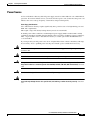
Cisco VG350 Voice Gateway Hardware
Installation Guide
THE SPECIFICATIONS AND INFORMATION REGARDING THE PRODUCTS IN THIS MANUAL ARE SUBJECT TO
CHANGE WITHOUT NOTICE. ALL STATEMENTS, INFORMATION, AND RECOMMENDATIONS IN THIS
MANUAL ARE BELIEVED TO BE ACCURATE BUT ARE PRESENTED WITHOUT WARRANTY OF ANY KIND,
EXPRESS OR IMPLIED. USERS MUST TAKE FULL RESPONSIBILITY FOR THEIR APPLICATION OF ANY
PRODUCTS.
Americas Headquarters
Cisco Systems, Inc.
170 West Tasman Drive
San Jose, CA 95134-1706
USA
http://www.cisco.com
Tel: 408 526-4000
800 553-NETS (6387)
Fax: 408 527-0883
Last Revised: December 5, 2012
Text Part Number: OL-25970-01
THE SOFTWARE LICENSE AND LIMITED WARRANTY FOR THE ACCOMPANYING PRODUCT ARE SET FORTH IN THE INFORMATION PACKET THAT
SHIPPED WITH THE PRODUCT AND ARE INCORPORATED HEREIN BY THIS REFERENCE. IF YOU ARE UNABLE TO LOCATE THE SOFTWARE LICENSE
OR LIMITED WARRANTY, CONTACT YOUR CISCO REPRESENTATIVE FOR A COPY.
The following information is for FCC compliance of Class A devices: This equipment has been tested and found to comply with the limits for a Class A digital device, pursuant
to part 15 of the FCC rules. These limits are designed to provide reasonable protection against harmful interference when the equipment is operated in a commercial
environment. This equipment generates, uses, and can radiate radio-frequency energy and, if not installed and used in accordance with the instruction manual, may cause
harmful interference to radio communications. Operation of this equipment in a residential area is likely to cause harmful interference, in which case users will be required
to correct the interference at their own expense.
The following information is for FCC compliance of Class B devices: This equipment has been tested and found to comply with the limits for a Class B digital device, pursuant
to part 15 of the FCC rules. These limits are designed to provide reasonable protection against harmful interference in a residential installation. This equipment generates,
uses and can radiate radio frequency energy and, if not installed and used in accordance with the instructions, may cause harmful interference to radio communications.
However, there is no guarantee that interference will not occur in a particular installation. If the equipment causes interference to radio or television reception, which can be
determined by turning the equipment off and on, users are encouraged to try to correct the interference by using one or more of the following measures:
• Reorient or relocate the receiving antenna.
• Increase the separation between the equipment and receiver.
• Connect the equipment into an outlet on a circuit different from that to which the receiver is connected.
• Consult the dealer or an experienced radio/TV technician for help.
Modifications to this product not authorized by Cisco could void the FCC approval and negate your authority to operate the product.
The Cisco implementation of TCP header compression is an adaptation of a program developed by the University of California, Berkeley (UCB) as part of UCB’s public
domain version of the UNIX operating system. All rights reserved. Copyright © 1981, Regents of the University of California.
NOTWITHSTANDING ANY OTHER WARRANTY HEREIN, ALL DOCUMENT FILES AND SOFTWARE OF THESE SUPPLIERS ARE PROVIDED “AS IS” WITH
ALL FAULTS. CISCO AND THE ABOVE-NAMED SUPPLIERS DISCLAIM ALL WARRANTIES, EXPRESSED OR IMPLIED, INCLUDING, WITHOUT
LIMITATION, THOSE OF MERCHANTABILITY, FITNESS FOR A PARTICULAR PURPOSE AND NONINFRINGEMENT OR ARISING FROM A COURSE OF
DEALING, USAGE, OR TRADE PRACTICE.
IN NO EVENT SHALL CISCO OR ITS SUPPLIERS BE LIABLE FOR ANY INDIRECT, SPECIAL, CONSEQUENTIAL, OR INCIDENTAL DAMAGES, INCLUDING,
WITHOUT LIMITATION, LOST PROFITS OR LOSS OR DAMAGE TO DATA ARISING OUT OF THE USE OR INABILITY TO USE THIS MANUAL, EVEN IF CISCO
OR ITS SUPPLIERS HAVE BEEN ADVISED OF THE POSSIBILITY OF SUCH DAMAGES.
Cisco and the Cisco logo are trademarks or registered trademarks of Cisco and/or its affiliates in the U.S. and other countries. To view a list of Cisco trademarks, go to this
URL: www.cisco.com/go/trademarks. Third-party trademarks mentioned are the property of their respective owners. The use of the word partner does not imply a partnership
relationship between Cisco and any other company. (1110R)
Any Internet Protocol (IP) addresses and phone numbers used in this document are not intended to be actual addresses and phone numbers. Any examples, command display
output, network topology diagrams, and other figures included in the document are shown for illustrative purposes only. Any use of actual IP addresses or phone numbers in
illustrative content is unintentional and coincidental.
Cisco VG350 Voice Gateway Hardware Installation Guide
© 2012 Cisco Systems, Inc. All rights reserved.
CONTENTS
Preface
vii
Audience
-vii
Organization
-vii
Conventions
-viii
Safety Warnings -ix
Warning Definition
-ix
Related Documentation -xv
Cisco.com -xv
Ordering Documentation -xvi
Documentation Feedback -xvi
Cisco Technical Support Website -xvi
Submitting a Service Request -xvii
Definitions of Service Request Severity -xvii
Obtaining Additional Publications and Information
CHAPTER
1
Overview of the Cisco VG350 Voice Gateway
Overview
-xviii
1-1
1-1
1-1
VG350 Voice Gateway Chassis 1-2
Configuration Options 1-3
Interfaces and Service Capabilities
Physical Description and LEDs
LED Indicators 1-4
Specifications 1-6
1-3
1-4
Software Elements 1-9
Configuration Connections 1-9
Configuration Methods 1-9
Automated Configuration 1-9
Manual Configuration 1-9
CHAPTER
2
Cisco Double-Wide High Density Analog
Service Modules 2-1
Double-Wide High Density Analog Service Module Overview
2-2
Cisco VG350 Voice Gateway Hardware Installation Guide
OL-25970-01
iii
Contents
Installing SM-D-72FXS 2-3
Grounding 2-3
Cables 2-3
Connecting SM-D-72FXS 2-3
Installing SM-D-48FXS-E 2-4
Grounding 2-4
Cables 2-4
Connecting SM-D-48FXS-E 2-4
FXO Fail-Over Bypass Ports
2-5
Cisco SM-D-72FXS Service Module Specifications
Physical Description and LEDs 2-6
Cisco SM-D-48FXS-E Service Module Specifications
Physical Description and LEDs 2-6
Port Numbering Conventions
2-6
2-6
2-7
Connecting to the Double-Wide High Density Service Module Ports
2-7
Online Insertion and Removal 2-7
Insertion and Removal Steps 2-8
Insertion 2-8
Removal 2-8
EN LED
CHAPTER
3
2-8
Planning Your Installation
3-1
Location and Mounting Requirements 3-1
Temperature Control and Ventilation 3-1
Enclosed Racks 3-2
Bench-Mounted 3-2
Access to Chassis 3-2
Chassis Grounding 3-2
Power Source 3-3
Cable Types 3-4
Distance Limitations for Interface Cables 3-4
Gigabit Ethernet Maximum Distance 3-4
FXS Analog Voice Port Maximum Distance 3-4
FXS-E (Extended loop) Analog Voice Port Maximum Distance
Interference Considerations
CHAPTER
4
3-5
Installing the Cisco VG350 Voice Gateway
Safety Recommendations
3-4
4-1
4-2
Cisco VG350 Voice Gateway Hardware Installation Guide
OL-25970-01
iv
Contents
Maintaining Safety with Electricity 4-2
General Safety Practices 4-4
Safety Tips 4-4
Preventing Electrostatic Discharge Damage
Site Log
4-5
4-5
Keeping Track–Checklist 4-6
Installation Checklist 4-6
Mounting Tools and Equipment
Unpacking and Inspection
CHAPTER
5
Power-On Procedure
Troubleshooting
A
4-7
Powering On the Cisco VG350 Voice Gateway
Checklist for Power-On
APPENDIX
4-7
5-1
5-1
5-1
5-3
Cable Specifications and Information
A-1
Console and Auxiliary Port Cables and Pinouts A-1
Console Port to PC A-2
Console Port to ASCII Terminal A-3
Auxiliary Port to Modem A-4
Alternative Connections to Terminal and Modem
Gigabit Ethernet Port Pinouts (RJ-45)
A-4
A-5
Analog Voice Multiport Pinouts (RJ-21X/CA21A)
A-6
Cisco VG350 Voice Gateway Hardware Installation Guide
OL-25970-01
v
Preface
This preface discusses the audience, organization, and conventions of this publication and describes how
to obtain additional documentation.
Audience
This publication is designed for experienced IT technicians familiar with Cisco products, IOS CLI, and
concepts and technologies of networking. This document can also be used by experienced
telecommunications administrators familiar with Cisco Unified Communications Manager and/or Cisco
Unified Communications Manager Business Edition and/or Cisco Unified Communications Manager
Express.
Warning
Only trained and qualified personnel should be allowed to install, replace, or service this equipment.
Statement 1030
Organization
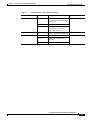
Table 1
Major Sections of This Guide
Chapter
Title
Chapter 1
Overview of the
Features and specifications of the Cisco VG350 Voice Gateway.
Cisco VG350 Voice Gateway
Chapter 2
Cisco Double-Wide High
Density Analog Service
Modules
Information including specifications of the the Double-Wide High Density
Service Modules.
Chapter 3
Planning Your Installation
Environmental requirements and cable routing considerations.
Chapter 4
Installing the Cisco VG350
Voice Gateway
Instructions for installing the Cisco VG350 Voice Gateway and connecting the
cables.
Chapter 5
Powering On the
Powering up the Cisco VG350 Voice Gateway and preparing for configuration.
Cisco VG350 Voice Gateway
Appendix A Cable Specifications and
Information
Description
Pinouts for the Cisco VG350 Voice Gateway ports and cables.
Cisco VG350 Voice Gateway Hardware Installation Guide
OL-25970-01
vii
Contents
Conventions
Table 2
Installation Guide Conventions
Convention
Description
boldface font
Commands and keywords.
italic font
Variables for which you supply values.
[
Keywords or arguments that appear within square brackets are optional.
]
{x | y | z}
A choice of required keywords appears in braces separated by vertical bars. You must select one.
screen font
Examples of information displayed on the screen.
boldface screen
font
Examples of information you must enter.
<
>
Nonprinting characters, for example, passwords, appear in angle brackets in contexts where italic font is
not available.
[
]
Default responses to system prompts appear in square brackets.
Note
Timesaver
Caution
Tip
Means reader take note. Notes contain helpful suggestions or references to materials not contained in
this publication.
Means the described action saves time. You can save time by performing the action described in the
paragraph.
Means reader be careful. In this situation, you might do something that could result in equipment
damage or loss of data.
Means the following information will help you solve a problem. The tips information might not be
troubleshooting or even an action, but could be useful information, similar to a Timesaver.
Cisco VG350 Voice Gateway Hardware Installation Guide
viii
OL-25970-01
Contents
Safety Warnings
Safety warnings appear throughout this publication in procedures that, if performed incorrectly, may
harm you. A warning symbol precedes each warning statement. To see translations of the warnings that
appear in this publication, refer to Cisco VG350 Voice Gateway Regulatory Compliance and Safety
Information.
Warning Definition
Warning
IMPORTANT SAFETY INSTRUCTIONS
This warning symbol means danger. You are in a situation that could cause bodily injury. Before you
work on any equipment, be aware of the hazards involved with electrical circuitry and be familiar
with standard practices for preventing accidents. Use the statement number provided at the end of
each warning to locate its translation in the translated safety warnings that accompanied this
device. Statement 1071
SAVE THESE INSTRUCTIONS
Waarschuwing
BELANGRIJKE VEILIGHEIDSINSTRUCTIES
Dit waarschuwingssymbool betekent gevaar. U verkeert in een situatie die lichamelijk letsel kan
veroorzaken. Voordat u aan enige apparatuur gaat werken, dient u zich bewust te zijn van de bij
elektrische schakelingen betrokken risico's en dient u op de hoogte te zijn van de standaard
praktijken om ongelukken te voorkomen. Gebruik het nummer van de verklaring onderaan de
waarschuwing als u een vertaling van de waarschuwing die bij het apparaat wordt geleverd, wilt
raadplegen.
BEWAAR DEZE INSTRUCTIES
Varoitus
TÄRKEITÄ TURVALLISUUSOHJEITA
Tämä varoitusmerkki merkitsee vaaraa. Tilanne voi aiheuttaa ruumiillisia vammoja. Ennen kuin
käsittelet laitteistoa, huomioi sähköpiirien käsittelemiseen liittyvät riskit ja tutustu
onnettomuuksien yleisiin ehkäisytapoihin. Turvallisuusvaroitusten käännökset löytyvät laitteen
mukana toimitettujen käännettyjen turvallisuusvaroitusten joukosta varoitusten lopussa näkyvien
lausuntonumeroiden avulla.
SÄILYTÄ NÄMÄ OHJEET
Attention
IMPORTANTES INFORMATIONS DE SÉCURITÉ
Ce symbole d'avertissement indique un danger. Vous vous trouvez dans une situation pouvant
entraîner des blessures ou des dommages corporels. Avant de travailler sur un équipement, soyez
conscient des dangers liés aux circuits électriques et familiarisez-vous avec les procédures
couramment utilisées pour éviter les accidents. Pour prendre connaissance des traductions des
avertissements figurant dans les consignes de sécurité traduites qui accompagnent cet appareil,
référez-vous au numéro de l'instruction situé à la fin de chaque avertissement.
CONSERVEZ CES INFORMATIONS
Cisco VG350 Voice Gateway Hardware Installation Guide
OL-25970-01
ix
Contents
Warnung
WICHTIGE SICHERHEITSHINWEISE
Dieses Warnsymbol bedeutet Gefahr. Sie befinden sich in einer Situation, die zu Verletzungen führen
kann. Machen Sie sich vor der Arbeit mit Geräten mit den Gefahren elektrischer Schaltungen und
den üblichen Verfahren zur Vorbeugung vor Unfällen vertraut. Suchen Sie mit der am Ende jeder
Warnung angegebenen Anweisungsnummer nach der jeweiligen Übersetzung in den übersetzten
Sicherheitshinweisen, die zusammen mit diesem Gerät ausgeliefert wurden.
BEWAHREN SIE DIESE HINWEISE GUT AUF.
Avvertenza
IMPORTANTI ISTRUZIONI SULLA SICUREZZA
Questo simbolo di avvertenza indica un pericolo. La situazione potrebbe causare infortuni alle
persone. Prima di intervenire su qualsiasi apparecchiatura, occorre essere al corrente dei pericoli
relativi ai circuiti elettrici e conoscere le procedure standard per la prevenzione di incidenti.
Utilizzare il numero di istruzione presente alla fine di ciascuna avvertenza per individuare le
traduzioni delle avvertenze riportate in questo documento.
CONSERVARE QUESTE ISTRUZIONI
Advarsel
VIKTIGE SIKKERHETSINSTRUKSJONER
Dette advarselssymbolet betyr fare. Du er i en situasjon som kan føre til skade på person. Før du
begynner å arbeide med noe av utstyret, må du være oppmerksom på farene forbundet med
elektriske kretser, og kjenne til standardprosedyrer for å forhindre ulykker. Bruk nummeret i slutten
av hver advarsel for å finne oversettelsen i de oversatte sikkerhetsadvarslene som fulgte med denne
enheten.
TA VARE PÅ DISSE INSTRUKSJONENE
Aviso
INSTRUÇÕES IMPORTANTES DE SEGURANÇA
Este símbolo de aviso significa perigo. Você está em uma situação que poderá ser causadora de
lesões corporais. Antes de iniciar a utilização de qualquer equipamento, tenha conhecimento dos
perigos envolvidos no manuseio de circuitos elétricos e familiarize-se com as práticas habituais de
prevenção de acidentes. Utilize o número da instrução fornecido ao final de cada aviso para
localizar sua tradução nos avisos de segurança traduzidos que acompanham este dispositivo.
GUARDE ESTAS INSTRUÇÕES
¡Advertencia!
INSTRUCCIONES IMPORTANTES DE SEGURIDAD
Este símbolo de aviso indica peligro. Existe riesgo para su integridad física. Antes de manipular
cualquier equipo, considere los riesgos de la corriente eléctrica y familiarícese con los
procedimientos estándar de prevención de accidentes. Al final de cada advertencia encontrará el
número que le ayudará a encontrar el texto traducido en el apartado de traducciones que acompaña
a este dispositivo.
GUARDE ESTAS INSTRUCCIONES
Cisco VG350 Voice Gateway Hardware Installation Guide
x
OL-25970-01
Contents
Varning!
VIKTIGA SÄKERHETSANVISNINGAR
Denna varningssignal signalerar fara. Du befinner dig i en situation som kan leda till personskada.
Innan du utför arbete på någon utrustning måste du vara medveten om farorna med elkretsar och
känna till vanliga förfaranden för att förebygga olyckor. Använd det nummer som finns i slutet av
varje varning för att hitta dess översättning i de översatta säkerhetsvarningar som medföljer denna
anordning.
SPARA DESSA ANVISNINGAR
Cisco VG350 Voice Gateway Hardware Installation Guide
OL-25970-01
xi
Contents
Aviso
INSTRUÇÕES IMPORTANTES DE SEGURANÇA
Este símbolo de aviso significa perigo. Você se encontra em uma situação em que há risco de lesões
corporais. Antes de trabalhar com qualquer equipamento, esteja ciente dos riscos que envolvem os
circuitos elétricos e familiarize-se com as práticas padrão de prevenção de acidentes. Use o
número da declaração fornecido ao final de cada aviso para localizar sua tradução nos avisos de
segurança traduzidos que acompanham o dispositivo.
GUARDE ESTAS INSTRUÇÕES
Advarsel
VIGTIGE SIKKERHEDSANVISNINGER
Dette advarselssymbol betyder fare. Du befinder dig i en situation med risiko for
legemesbeskadigelse. Før du begynder arbejde på udstyr, skal du være opmærksom på de
involverede risici, der er ved elektriske kredsløb, og du skal sætte dig ind i standardprocedurer til
undgåelse af ulykker. Brug erklæringsnummeret efter hver advarsel for at finde oversættelsen i de
oversatte advarsler, der fulgte med denne enhed.
GEM DISSE ANVISNINGER
Cisco VG350 Voice Gateway Hardware Installation Guide
xii
OL-25970-01
Contents
Cisco VG350 Voice Gateway Hardware Installation Guide
OL-25970-01
xiii
Contents
Cisco VG350 Voice Gateway Hardware Installation Guide
xiv
OL-25970-01
Contents
Related Documentation
The Cisco IOS software running your Cisco Voice Gateway includes extensive features and
functionality. For information that is beyond the scope of this document, or for additional information,
use the resources listed in Table 3.
Timesaver
Table 3
Make sure that you have access to the documents listed in Table 3. See the “Obtaining Documentation”
section on page xv for information about obtaining these documents.
Related and Referenced Documents
Cisco Product
Cisco VG350 Voice
Gateway
Cisco IOS software1
Document Title
•
Cisco VG350 Voice Gateway Hardware Installation Guide (this book)
•
Cisco VG350 Voice Gateway Software Configuration Guide
•
Cisco VG350 Voice Gateway Regulatory Compliance and Safety Information
•
Release 15.2(4)M New Features and Important Notes
1. Refer to the modular reference publications that correspond to the Cisco IOS software release installed on your Cisco VG350 Voice Gateway.
Obtaining Documentation
Cisco documentation and additional literature are available on Cisco.com. Cisco also provides several
ways to obtain technical assistance and other technical resources. These sections explain how to obtain
technical information from Cisco Systems.
Cisco.com
You can access the most current Cisco documentation at this URL:
http://www.cisco.com/univercd/home/home.htm
You can access the Cisco website at this URL:
http://www.cisco.com
You can access international Cisco websites at this URL:
http://www.cisco.com/public/countries_languages.shtml
Cisco VG350 Voice Gateway Hardware Installation Guide
OL-25970-01
xv
Contents
Ordering Documentation
You can find instructions for ordering documentation at this URL:
http://www.cisco.com/univercd/cc/td/doc/es_inpck/pdi.htm
You can order Cisco documentation in these ways:
•
Registered Cisco.com users (Cisco direct customers) can order Cisco product documentation from
the Ordering tool:
http://www.cisco.com/en/US/partner/ordering/index.shtml
•
Nonregistered Cisco.com users can order documentation through a local account representative by
calling Cisco Systems Corporate Headquarters (California, USA) at 408 526-7208 or, elsewhere in
North America, by calling 800 553-NETS (6387).
Documentation Feedback
You can send comments about technical documentation to [email protected].
You can submit comments by using the response card (if present) behind the front cover of your
document or by writing to the following address:
Cisco Systems
Attn: Customer Document Ordering
170 West Tasman Drive
San Jose, CA 95134-9883
We appreciate your comments.
Obtaining Technical Assistance
For all customers, partners, resellers, and distributors who hold valid Cisco service contracts, Cisco
Technical Support provides 24-hour-a-day, award-winning technical assistance. The Cisco Technical
Support Website on Cisco.com features extensive online support resources. In addition, Cisco Technical
Assistance Center (TAC) engineers provide telephone support. If you do not hold a valid Cisco service
contract, contact your reseller.
Cisco Technical Support Website
The Cisco Technical Support Website provides online documents and tools for troubleshooting and
resolving technical issues with Cisco products and technologies. The website is available 24 hours a day,
365 days a year at this URL:
http://www.cisco.com/techsupport
Access to all tools on the Cisco Technical Support Website requires a Cisco.com user ID and password.
If you have a valid service contract but do not have a user ID or password, you can register at this URL:
http://tools.cisco.com/RPF/register/register.do
Cisco VG350 Voice Gateway Hardware Installation Guide
xvi
OL-25970-01
Contents
Submitting a Service Request
Using the online TAC Service Request Tool is the fastest way to open S3 and S4 service requests. (S3
and S4 service requests are those in which your network is minimally impaired or for which you require
product information.) After you describe your situation, the TAC Service Request Tool automatically
provides recommended solutions. If your issue is not resolved using the recommended resources, your
service request will be assigned to a Cisco TAC engineer. The TAC Service Request Tool is located at
this URL:
http://www.cisco.com/techsupport/servicerequest
For S1 or S2 service requests or if you do not have Internet access, contact the Cisco TAC by telephone.
(S1 or S2 service requests are those in which your production network is down or severely degraded.)
Cisco TAC engineers are assigned immediately to S1 and S2 service requests to help keep your business
operations running smoothly.
To open a service request by telephone, use one of the following numbers:
Asia-Pacific: +61 2 8446 7411 (Australia: 1 800 805 227)
EMEA: +32 2 704 55 55
USA: 1 800 553 2447
For a complete list of Cisco TAC contacts, go to this URL:
http://www.cisco.com/techsupport/contacts
Definitions of Service Request Severity
To ensure that all service requests are reported in a standard format, Cisco has established severity
definitions.
Severity 1 (S1)—Your network is “down,” or there is a critical impact to your business operations. You
and Cisco will commit all necessary resources around the clock to resolve the situation.
Severity 2 (S2)—Operation of an existing network is severely degraded, or significant aspects of your
business operation are negatively affected by inadequate performance of Cisco products. You and Cisco
will commit full-time resources during normal business hours to resolve the situation.
Severity 3 (S3)—Operational performance of your network is impaired, but most business operations
remain functional. You and Cisco will commit resources during normal business hours to restore service
to satisfactory levels.
Severity 4 (S4)—You require information or assistance with Cisco product capabilities, installation, or
configuration. There is little or no effect on your business operations.
Cisco VG350 Voice Gateway Hardware Installation Guide
OL-25970-01
xvii
Contents
Obtaining Additional Publications and Information
Information about Cisco products, technologies, and network solutions is available from various online
and printed sources.
•
Cisco Marketplace provides a variety of Cisco books, reference guides, and logo merchandise. Visit
Cisco Marketplace, the company store, at this URL:
http://www.cisco.com/go/marketplace/
•
The Cisco Product Catalog describes the networking products offered by Cisco Systems, as well as
ordering and customer support services. Access the Cisco Product Catalog at this URL:
http://cisco.com/univercd/cc/td/doc/pcat/
•
Cisco Press publishes a wide range of general networking, training and certification titles. Both new
and experienced users will benefit from these publications. For current Cisco Press titles and other
information, go to Cisco Press at this URL:
http://www.ciscopress.com
•
Packet magazine is the Cisco Systems technical user magazine for maximizing Internet and
networking investments. Each quarter, Packet delivers coverage of the latest industry trends,
technology breakthroughs, and Cisco products and solutions, as well as network deployment and
troubleshooting tips, configuration examples, customer case studies, certification and training
information, and links to scores of in-depth online resources. You can access Packet magazine at this
URL:
http://www.cisco.com/packet
•
Internet Protocol Journal is a quarterly journal published by Cisco Systems for engineering
professionals involved in designing, developing, and operating public and private internets and
intranets. You can access the Internet Protocol Journal at this URL:
http://www.cisco.com/ipj
•
World-class networking training is available from Cisco. You can view current offerings at
this URL:
http://www.cisco.com/en/US/learning/index.html
Cisco VG350 Voice Gateway Hardware Installation Guide
xviii
OL-25970-01
CH A P T E R
1
Overview of the Cisco VG350 Voice Gateway
This chapter provides a brief description of the Cisco VG350 Voice Gateway (VG) and contains the
following sections:
•
Overview, page 1-1
•
VG350 Voice Gateway Chassis, page 1-2
•
Interfaces and Service Capabilities, page 1-3
•
Physical Description and LEDs, page 1-4
•
Software Elements, page 1-9
Overview
The Cisco VG350 service module is a high-density analog voice gateway. It is an intermediate path that
enables TDM to IP transition.
The Cisco VG350 Voice Gateway supports the following interfaces:
Warning
•
Gigabit Ethernet (GE)
•
USB
•
High-Speed WAN Interface Card (HWIC) and Voice/WAN Interface Card (VWIC)
•
Double-Wide Service Module (DWSM) interface
This unit is intended for installation in restricted access areas. A restricted access area can be
accessed only through the use of a special tool, lock and key, or other means by security.
Statement 1017
Cisco VG350 Voice Gateway Hardware Installation Guide
OL-25970-01
1-1
Chapter 1
Overview of the Cisco VG350 Voice Gateway
VG350 Voice Gateway Chassis
VG350 Voice Gateway Chassis
The following figures show the front and back panels of the VG350 Voice Gateway Chassis:
Figure 1-1
•
Figure 1-1 shows the Front Panel.
•
Figure 1-2 shows the Back Panel.
Front Panel of the VG350 Voice Gateway
2
3
4
1
344081
1
1
AC OK1
3
ACT status LED
2
SYS status LED
4
PS1 (Right), PS2 (Left)
1. LED goes off if the AC power fails or is disconnected. It does not go on and off with the power switch.
Figure 1-2
Back Panel of the VG350 Voice Gateway
1
2
3
4
5
6
VG350
344082
MB
8
9
10
7
Cisco VG350 Voice Gateway Hardware Installation Guide
1-2
OL-25970-01
Chapter 1
Overview of the Cisco VG350 Voice Gateway
Interfaces and Service Capabilities
1
USB serial console port
6
USB0 and USB1 (1, Top)
2
RJ-45 serial console port
7
Ground
3
SFP1 and SFP2 (2, Top)
8
CompactFlash 0 and 1 (0, Far right)
4
10/100/1000 Ethernet ports GE 0/1 and GE
0/2 (GE 0/2,Top)
9
SM-D-72FXS Service Module
5
10/100/1000 Ethernet port GE 0/0
10 SM-D-48FXS-E Service Module
Configuration Options
The following configuration options are available for Cisco VG350 Voice Gateway:
Table 1-1
Configuration Options Possible with Cisco VG350 Voice Gateway with the Double-Wide
High Density Analog Service Module (DWSM)
VG350
Configuration
SM 1
SM 2
Total number of ports
1
SM-D-72FXS
SM-D-72FXS
144
2
SM-D-72FXS
SM-D-48FXS-E
120
4
SM-D-48FXS-E
SM-D-48FXS-E
96
Interfaces and Service Capabilities
Table 1-2 lists the built-in interface ports for the Cisco VG350.
Table 1-2
Built-in Interfaces for the Cisco VG350
Data Ports
10/100/1000
GE RJ-45
Cisco VG350 Voice
Gateway
3
1
10/100/1000
SFP
2
Management Ports
USB Type A
Console Serial,
RJ-45
Console Serial,
Mini-USB
Auxiliary,
(Type B)
RJ-45
2
1
1
1
1. One RJ-45 with two GE SFPs or three RJ-45 GEs.
Cisco VG350 Voice Gateway Hardware Installation Guide
OL-25970-01
1-3
Chapter 1
Overview of the Cisco VG350 Voice Gateway
Physical Description and LEDs
Physical Description and LEDs
LED Indicators
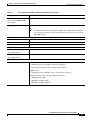
Table 1-3 describes the LED indicators for the Cisco VG350.
Table 1-3
LED Indicators for Cisco VG350
LED
Color
Description
Location on the VG350
PS/PS1
Green
System is running.
Front bezel
Amber
System is not running.
Green
System is running.
Amber
System is not running.
Green
AC power connected.
Off
No AC power connected
RPS
Green
System is running on external
RPS power supply.
—
SYS
Solid green
Solid green indicates normal
operation.
Front bezel
PS2
AC OK
Front bezel
Front bezel
Blinking green System is booting or is in ROM
monitor mode.
Amber
System error.
Off
Power is off or system board is
faulty.
Solid or
blinking green
Solid or blinking indicates
packet activity between the
forwarding and routing engine
and any I/O port.
Off
No packet transfers are
occurring.
RJ-45 CON
Green
Serial console is active.
Back panel
USB CON
Green
USB console is active.
Back panel
GE: Link
Green
Solid green indicates the
Ethernet port has a link partner.
Back panel
SFP S
Blinking green Blinking frequency indicates
Back panel
port speed. See the definition for
the S LED.
SFP EN
Off
Not present.
Green
Present and enabled.
Amber
Present with failure.
ACT
Front bezel
Back panel
Cisco VG350 Voice Gateway Hardware Installation Guide
1-4
OL-25970-01
Chapter 1
Overview of the Cisco VG350 Voice Gateway
Physical Description and LEDs
Table 1-3
LED Indicators for Cisco VG350 (continued)
LED
Color
Description
CF0/CF1
Green
Flash memory is being accessed; Back panel
do not eject the CompactFlash
memory card.
Amber
CompactFlash error.
Off
Flash memory is not being
accessed; okay to eject the
CompactFlash memory card.
Off
No FE or GE link is established.
Green
PVDM is initialized.
Amber
PVDM is detected but not
initialized.
Off
No PVDM installed.
PVDM 0,1,2, and 3
Location on the VG350
Back panel
Cisco VG350 Voice Gateway Hardware Installation Guide
OL-25970-01
1-5
Chapter 1
Overview of the Cisco VG350 Voice Gateway
Physical Description and LEDs
Specifications
Table 1-4 details the technical specifications of the Cisco VG350 Voice Gateway.
Table 1-4
Cisco VG350 Voice Gateway Technical Specifications
Description
Specification
Physical
Dimensions (H x W x D)
5.22 x 17.25 x 18.75 in. (88.9 x 438.2 x 476.2 mm), 3 RU height
Weight with AC PS
39 lbs (17.69 kg)
(without modules)
Weight with AC PS
40 lbs (18.14 kg)
(without modules)
Weight (fully configured)
60 lbs (27.21 kg)
Power
AC input power
•
Input voltage
100 to 240 VAC, autoranging
•
Frequency
47 to 63 Hz
•
Input current
0.4 to 3.5 A (configuration dependent)
•
Input current with AC
0.4 to 7.0 A (configuration dependent)
•
Surge current
30 A maximum at 115 VAC 60 Hz
60 A maximum at 230 VAC 50 Hz
Power consumption
85 to 400 W, 600 to 1370 BTU/hr (configuration dependent)
With AC
85 to 800 W, 600 to 2740 BTU/hr (configuration dependent)
Ports
Console port
One RJ-45 connector and one mini USB Type B, USB 2.0 compliant
Auxiliary port
RJ-45 connector
USB ports
Two USB Type A, USB 2.0 compliant, 2.5 W (500 mA) maximum1
10/100/1000 Gigabit Ethernet
Three RJ-45 connectors (GE 0/0, GE 0/1, GE 0/2) auto-MDIX2
SFP
Two RJ-45 connectors support SFP modules. When an SFP module is installed, the
adjacent RJ-45 GE connector is disabled.
Environmental
Operating humidity
5 to 85%, noncondensing
Operating humidity
5% to 90%, but not to exceed 0.024 kg water/kg of dry air
(short-term per NEBS)
Operating temperature up to
5906 ft (1800 m) elevation
32 to 104°F (0 to 40°C)
Operating temperature up to
9843 ft (3000 m) elevation
32 to 104°F (0 to 40°C)
Operating temperature up to
32 to 86°F (0 to 30°C)
13,123 ft (4000 m) elevation
Cisco VG350 Voice Gateway Hardware Installation Guide
1-6
OL-25970-01
Chapter 1
Overview of the Cisco VG350 Voice Gateway
Physical Description and LEDs
Table 1-4
Cisco VG350 Voice Gateway Technical Specifications (continued)
Description
Specification
Temperature
23 to 122°F (–5°C to 50°C)
(short-term per NEBS/1800m
max altitude)
Operating altitude maximum
13,123 ft (4000 m)
Note
For China, the unit cannot operate above 2000 m. The internal AC power supplies
do not meet the new Chinese Safety requirements for products that operate in the
2001-5000 m range.
Transportation and Storage
Non-operating temperature
–40 to 158°F (–40 to 70°C)
Non-operating humidity
5 to 95% RH
Non-operating altitude
15,000 ft (4570 m)
Acoustic
Acoustic: Sound Pressure
57.6 to 77.6 dBA
(Typical/Maximum)
Acoustic: Sound Power
67.8 to 84.7 dBA
(Typical/Maximum)
Compliance
Safety compliance
•
IEC 60950-1, Safety of information technology equipment
•
EN 60950-1, Safety of information technology equipment
•
UL 60950-1, Standard for safety for information technology
equipment [US]
•
CAN/CSA C22.2 No. 60950-1, Safety of information technology
equipment including electrical business equipment [Canada]
•
AS/NZS 60950.1 2003
•
IEC60950, 3rd edition [PRC]
•
IEC60950, 2nd Edition [Mexico]
Cisco VG350 Voice Gateway Hardware Installation Guide
OL-25970-01
1-7
Chapter 1
Overview of the Cisco VG350 Voice Gateway
Physical Description and LEDs
Table 1-4
Cisco VG350 Voice Gateway Technical Specifications (continued)
Description
Specification
Immunity compliance
EMC compliance
•
CISPR24 ITE-Immunity characteristics, Limits and methods of measurement
•
EN 55024 ITE-Immunity characteristics, Limits and methods ofmeasurement
•
EN 50082-1 Electromagnetic compatibility - Generic immunity standard - Part 1
•
EN 300-386 Electromagnetic compatibility for TNESD/EMI
•
EN 61000-6-1
•
SD/EMI
•
EN 55022, Class A
•
CISPR22, Class A
•
CFR47, Part 15, Subpart B, Class A
•
EN300386, Class A
•
AS/NZS CISPR22, Class A
•
VCCI, Class A
•
SD/EMI, Class A
•
Harmonic Current Emission
– EN 61000-3-2 for EUT Power requirements <16A
– EN 61000-3-12 for EUT Power requirements >16A
•
Voltage Fluctuation and Flicker
– EN 61000-3-3 for EUT Power requirements <16
– EN 61000-3-11 for EUT Power requirements >16A
1. 480 Mb/s individually, bandwidth is shared when both are used.
Warning
Ultimate disposal of this product should be handled according to all national laws and regulations.
Statement 1040
Cisco VG350 Voice Gateway Hardware Installation Guide
1-8
OL-25970-01
Chapter 1
Overview of the Cisco VG350 Voice Gateway
Software Elements
Software Elements
The operating system for the Cisco VG350 Voice Gateway is the Cisco IOS software that resides in flash
memory.
Configuration Connections
You can use an ASCII terminal or a PC to configure a Cisco VG350 Voice Gateway. The configuration
can be performed in several ways:
•
Locally, with a direct connection through the console port
•
Remotely, with a connection through the auxiliary port and a modem
•
Through Telnet and TFTP
Configuration Methods
Automated Configuration
If your Cisco VG350 Voice Gateway was ordered with the Simple Network-Enabled Auto-Provision
(SNAP) option, no onsite configuration is required. When the Cisco VG350 Voice Gateway is powered
on and connected, the SNAP application downloads the applicable configuration files automatically.
Manual Configuration
When a Cisco VG350 Voice Gateway is first installed, use the procedure in the “Power-On Procedure”
section on page 5-1 for the initial configuration. This sets the basic communication parameters.
After the Cisco VG350 Voice Gateway is operating and able to communicate, use the procedures in
Cisco VG350 Voice Gateway Software Configuration Guide to configure the specific services and
functions or to make changes to the existing configuration.
There are multiple methods for configuring a Cisco VG350 Voice Gateway:
•
System configuration dialog
•
Configuration mode—Cisco IOS software CLI
•
setup command facility—Remote configuration through a LAN
•
SNMP-based application—CiscoView or HP OpenView
•
HTTP-based configuration server—Provides access to the CLI from a web browser
Cisco VG350 Voice Gateway Hardware Installation Guide
OL-25970-01
1-9
Chapter 1
Overview of the Cisco VG350 Voice Gateway
Software Elements
Cisco VG350 Voice Gateway Hardware Installation Guide
1-10
OL-25970-01
CH A P T E R
2
Cisco Double-Wide High Density Analog
Service Modules
This chapter provides information about the following Double-Wide High Denstiy Analog Service
Module (DWSM).
Note
1.
Cisco SM-D-72FXS Service Module—A 72 FXS port DWSM with 4 out of the 72 ports supporting
OPX ‘Lite’ capabilities.
2.
Cisco SM-D-48FXS-E Service Module—A 48 FXS port DWSM with all 48 ports supporting OPX
Lite capabilities.
DWSM refers to both the Cisco SM-D-72FXS and SM-D-48FXS-E Service Module.
This chapter contains the following sections:
•
Double-Wide High Density Analog Service Module Overview, page 2-2
•
FXO Fail-Over Bypass Ports, page 2-5
•
Cisco SM-D-72FXS Service Module Specifications, page 2-6
•
Cisco SM-D-48FXS-E Service Module Specifications, page 2-6
•
Port Numbering Conventions, page 2-7
•
Connecting to the Double-Wide High Density Service Module Ports, page 2-7
•
Online Insertion and Removal, page 2-7
Cisco VG350 Voice Gateway Hardware Installation Guide
OL-25970-01
2-1
Chapter 2
Cisco Double-Wide High Density Analog Service Modules
Double-Wide High Density Analog Service Module Overview
Double-Wide High Density Analog Service Module Overview
The Double-Wide High Density Service Module (DWSM) is supported on the following platforms:
•
Cisco 3945
•
Cisco 3945e
•
Cisco 3925
•
Cisco 3925e
•
Cisco 2951
The modules can be plugged in the following DWSM slots of the following platforms:
•
On Cisco 3945 and Cisco 3945e - only on slot 4.
•
On Cisco 3925, Cisc0 3925e and Cisco 2951 - only on slot 2.
Table 2-1 shows the comparison between Cisco SM-D-72FXS and SM-D-48FXS-E.
Table 2-1
Feature comparison of SM-D-72FXS and SM-D-48FXS-E
Number of FXS Ports
SM-D-72FXS
SM-D-48FXS-E
72 (Port 0 to Port 71)
48 (Port 0 to Port 47)
Number of Ports Configurable as 4
FXS-E
(Port 0 to Port 3)
48
Max RENs/Port
5 REN/FXS Port
5 REN/FXS Port
2 REN/FXS-E Port
2 REN/FXS-E Port
Total REN Per DWSM Module
40
30
RJ-21 Connectors
3
2
2
2
(FXO Bypass Port 0: PSTN to
Port 46)
(FXO Bypass Port 0: PSTN to
Port 46)
FXO Bypass Port 1: PSTN to
Port 47)
FXO Bypass Port 1: PSTN to
Port 47)
FXO Bypass Ports
1
(all ports)
1. Each FXO Bypass Port are made up of two RJ-11 connectors for PSTN In and Out.
Cisco VG350 Voice Gateway Hardware Installation Guide
2-2
OL-25970-01
Chapter 2
Cisco Double-Wide High Density Analog Service Modules
Double-Wide High Density Analog Service Module Overview
Installing SM-D-72FXS
Install the SM-D-72FXS according to the instructions in the Installing Cisco Interface Cards in Cisco
Access Routers document.
Grounding
Ensure that the equipment you are working with is properly grounded according to the instructions in
the Installing Cisco Interface Cards in Cisco Access Routers document.
Cables
The VG350 Voice Gateway uses RJ-21 cables to connect to a distribution box.
Warning
To avoid electric shock, do not connect safety extra-low voltage (SELV) circuits to telephone-network
voltage (TNV) circuits. LAN ports contain SELV circuits, and WAN ports contain TNV circuits. Some
LAN and WAN ports both use RJ-45 connectors. Use caution when connecting cables. Statement 1021
Warning
Hazardous network voltages are present in WAN ports regardless of whether power to the unit is OFF
or ON. To avoid electric shock, use caution when working near WAN ports. When detaching cables,
detach the end away from the unit first. Statement 1026
Warning
This equipment contains a ring signal generator (ringer), which is a source of hazardous voltage. Do
not touch the RJ-11 (phone) port wires (conductors), the conductors of a cable connected to the RJ-11
port, or the associated circuit-board when the ringer is active. The ringer is activated by an incoming
call. Statement 1042
Warning
For connections outside the building where the equipment is installed, the following ports must be
connected through an approved network termination unit with integral circuit protection: FXS.
Statement 1044
Connecting SM-D-72FXS
To connect the SM-D-72FXS, follow the these steps:
Step 1
Confirm that the router is turned off.
Step 2
Connect one end of the straight-through RJ-21 cable to an RJ-21 distribution box.
Step 3
Connect the distribution box ports to a telephone or FAX machine using RJ-11 cable.
Step 4
Power up the router.
Cisco VG350 Voice Gateway Hardware Installation Guide
OL-25970-01
2-3
Chapter 2
Cisco Double-Wide High Density Analog Service Modules
Double-Wide High Density Analog Service Module Overview
Installing SM-D-48FXS-E
Install the SM-D-72FXS according to the instructions in the Installing Cisco Interface Cards in Cisco
Access Routers document.
Grounding
Ensure that the equipment you are working with is properly grounded according to the instructions in
the Installing Cisco Interface Cards in Cisco Access Routers document.
Cables
The VG350 Voice Gateway uses RJ-21 cables to connect to a distribution box.
Warning
To avoid electric shock, do not connect safety extra-low voltage (SELV) circuits to telephone-network
voltage (TNV) circuits. LAN ports contain SELV circuits, and WAN ports contain TNV circuits. Some
LAN and WAN ports both use RJ-45 connectors. Use caution when connecting cables. Statement 1021
Warning
Hazardous network voltages are present in WAN ports regardless of whether power to the unit is OFF
or ON. To avoid electric shock, use caution when working near WAN ports. When detaching cables,
detach the end away from the unit first. Statement 1026
Warning
This equipment contains a ring signal generator (ringer), which is a source of hazardous voltage. Do
not touch the RJ-11 (phone) port wires (conductors), the conductors of a cable connected to the RJ-11
port, or the associated circuit-board when the ringer is active. The ringer is activated by an incoming
call. Statement 1042
Warning
For connections outside the building where the equipment is installed, the following ports must be
connected through an approved network termination unit with integral circuit protection: FXS.
Statement 1044
Connecting SM-D-48FXS-E
To connect the SM-D-48FXS-E, follow the these steps:
Step 1
Confirm that the router is turned off.
Step 2
Connect one end of the straight-through RJ-21 cable to an RJ-21 distribution box.
Step 3
Connect the distribution box ports to a telephone or FAX machine using an RJ-11 cable.
Step 4
Power up the router.
Cisco VG350 Voice Gateway Hardware Installation Guide
2-4
OL-25970-01
Chapter 2
Cisco Double-Wide High Density Analog Service Modules
FXO Fail-Over Bypass Ports
FXO Fail-Over Bypass Ports
Bypass/Failover Port, also called Fail-over Trunk Bypass, provides a way to use designated analog phone
ports to make phone calls through the Public Switch Telephone Network (PSTN) during power-outage
or power savings circumstances.
Table 2-2 shows the RJ-11 connector assignment.
Table 2-2
Faceplate
Label
FXO
BYPASS-0
FXO
BYPASS-1
RJ-11 Connector Assignment
IN (RJ-11)
OUT (RJ-11)
Power ON
Power OFF
To PSTN
To external
FXO Interface
PSTN to external FXO
Interface
PSTN to RJ-21
connector Port 46
(optional)
FXS Port 46 to RJ-21
connector
No connection to
external FXO I/F
To external
FXO Interface
PSTN to external FXO
Interface
PSTN to RJ-21
connector Port 47
(optional)
FXS Port 47 to RJ-21
connector
No connection to
external FXO I/F
To PSTN
Cisco VG350 Voice Gateway Hardware Installation Guide
OL-25970-01
2-5
Chapter 2
Cisco Double-Wide High Density Analog Service Modules
Cisco SM-D-72FXS Service Module Specifications
Cisco SM-D-72FXS Service Module Specifications
Physical Description and LEDs
All interface ports and LEDs are on the rear of the chassis. Figure 2-1 illustrates their locations.
Cisco SM-D-72FXS Service Module LEDs
344083
Figure 2-1
2
1
1
2
EN LED
FXO Bypass ports
Cisco SM-D-48FXS-E Service Module Specifications
Physical Description and LEDs
All interface ports and LEDs are on the rear of the chassis. Figure 2-2 illustrates their locations.
Cisco SM-D-48FXS-E Service Module LEDs
344084
Figure 2-2
2
1
1
EN LED
2
FXO Bypass ports
Cisco VG350 Voice Gateway Hardware Installation Guide
2-6
OL-25970-01
Chapter 2
Cisco Double-Wide High Density Analog Service Modules
Port Numbering Conventions
Port Numbering Conventions
Port numbering conventions for the Cisco VG350 Voice Gateway are as follows:
•
Two Compact Flash slots, CF0 and CF1.
•
GE ports are 10/100/1000 BASE-T, numbered GE 0/0 through GE 0/2.
•
10/100BASE-T ports are numbered 10/100BASE-T 0/0 and 10/100BASE-T 0/1 from right to left.
•
FXS voice port numbering begins at 2/0/0 to 2/0/71 or 2/0/47 and 4/0/0 to 4/0/71 or 4/0/47,
depending on the number of voice ports.
The ports numbered 2/0/x are for the SM installed in slot 1 and the ports numbered 4/0/x are for the
Service Module (SM) installed in slot 2.
Connecting to the Double-Wide High Density Service Module
Ports
Three RJ-21 female connectors are available on the SM-D-72FXS service module. The middle RJ-21
connector accesses FXS ports 0 to 23, the left RJ-21 female connector accesses ports 24 to 4, and the
right RJ-21 connector accesses ports 48 to 71. Use RJ-21 male connector to connect from the DWSM
RJ-21 ports to an FXS port RJ-11 distribution box.
Note
Use an RJ-21 cable with Amphenol 50-pin connectors.
Online Insertion and Removal
The DWSM can be hot-inserted into the VG350 Voice Gateway without any potential of electrical
damage either to the SM or the Host because the Online Insertion and Removal (OIR) logic is present
on all SM designs.
OIRl is the ability to insert and remove an SM while the system is running without causing electrical
damage to the SM or Host and without interfering with the operation of any other modules or portions
of a running system.
The basic feature for OIR support on an SM is the control and isolation of the 12V power rail via a
field-effect transistor (FET). This FET is enabled in a controlled fashion after the SM card is fully
inserted.
Cisco VG350 Voice Gateway Hardware Installation Guide
OL-25970-01
2-7
Chapter 2
Cisco Double-Wide High Density Analog Service Modules
EN LED
Insertion and Removal Steps
This section describes the sequence of steps when inserting or removing a DWSM. OIR can only be done
on one service module at a time. It only supports the same service module type. If you remove an
SM-D-72FXS, only another SM-D-72FXS can be inserted.
Insertion
The following steps show how to insert a service module.
1.
Insert the service module into the slot.
2.
Make sure that the following message is displayed:
*Apr 19 00:14:19.177: %LINK-3-UPDOWN: Interface Foreign Exchange Station x/y/z,
changed state to up
Note
There are about 72 or 48 messages being displayed so it may take some time for the message to appear.
Estimated waiting time is approximately 2 minutes.
3.
Use the following command to verify the voice ports after insertion.
show voice port summary
Removal
The following steps show how to remove a service module.
1.
Ensure there is no active call on the service module that you want to remove.
Use the following command to find any active call in the system:
show voice call status
2.
Use the following command to proceed:
hw-module sm x oir-stop
where x is the slot number of the Service Module
3.
Wait until the following message is displayed:
SM Hardware slot 2 can be removed
4.
Remove the service module from its slot.
EN LED
Each Service Module(SM) has an Enable LED that is mounted on the SM and visible through the
faceplate of the SM. The EN LED includes:
•
Green / Amber Dual Color LED
•
Defaults to OFF / ON power up
Cisco VG350 Voice Gateway Hardware Installation Guide
2-8
OL-25970-01
CH A P T E R
3
Planning Your Installation
Before you install your Cisco VG350 Voice Gateway, consider the information in this chapter:
•
Location and Mounting Requirements, page 3-1
•
Distance Limitations for Interface Cables, page 3-4
•
Interference Considerations, page 3-5
Location and Mounting Requirements
The three mounting possibilities for your Cisco VG350 Voice Gateway are as follows:
•
Rack-mount
•
Wall-mount
•
Bench-top
The mounting location must provide the following:
•
Access to the chassis
•
Access to a suitable power source
•
Access to an appropriate earth ground
•
Allowance for adequate heat dissipation and airflow around the chassis
Temperature Control and Ventilation
The installation location (room, closet, or cabinet) for the Cisco VG350 Voice Gateway should always
be well ventilated and provide adequate air circulation to ensure proper cooling. The room temperature
should be maintained between 32 to 122°F (0 to 50°C).
Note
The Cisco VG350 Voice Gateway chassis is designed for back and sides-to-front airflow.
Cisco VG350 Voice Gateway Hardware Installation Guide
OL-25970-01
3-1
Chapter 3
Planning Your Installation
Location and Mounting Requirements
Enclosed Racks
Caution
Enclosed racks must have adequate ventilation. An enclosed rack should never be overcrowded and
should have louvers and a fan.
If the Cisco VG350 Voice Gateway is installed in an enclosed rack with a ventilation fan at the top, make
sure that heated air drawn upward from other equipment does not prevent adequate cooling.
If the chassis is installed using slide rails, check for blocked ventilation ports when it is in position in
the rack or cabinet. Make sure that the ventilation ports of the Cisco VG350 Voice Gateway are not
blocked.
Tip
Baffles can help isolate exhaust air from intake air. Baffles also help draw cooling air through the
cabinet. The best location for the baffles depends on the airflow patterns in the rack. You can test the
airflow by experimenting with different equipment arrangements.
Bench-Mounted
If the unit is placed on a bench-top, do not stack other equipment or paper on the chassis. Provide plenty
of space for air circulation (front to back). Inadequate ventilation can result in overheating and damage.
Access to Chassis
Allow space at the rear of the chassis for cable connections. Also consider the need to access the chassis
for future upgrades, maintenance, and troubleshooting.
Chassis Grounding
Chassis grounding is provided through the power cable, which uses a standard grounding plug. However,
the chassis also requires a reliable earth ground using the earth ground lug and hardware provided.
Cisco VG350 Voice Gateway Hardware Installation Guide
3-2
OL-25970-01
Chapter 3
Planning Your Installation
Location and Mounting Requirements
Power Source
A Cisco VG350 Voice Gateway with AC power supply autoselects either 100–127 volt or 200–240 volt
operation. AC versions include a 6-foot (1.8-meter) electrical power cord. (A label near the power cord
indicates the correct voltage, frequency, current draw, and power dissipation.)
Power Suppy Considerations
Cisco VG350 Voice Gateway requires significantly more power because of its high-density ports and
OPX ‘Lite’ requirements.
This require a larger 48V battery backup that may need to be custom built.
To handle power failure conditions, an uninterrupted power supply (UPS) is needed. UPS is widely
available in all markets, including emerging markets (due to prevalence of UPS for personal computers).
Thus, a separate UPS for Cisco VG350 Voice Gateway is a viable option when the ISR/UPS is not
co-located with it.
If you suspect that your AC power is not clean—if lights flicker often or there is machinery with large
motors nearby—have a qualified person test the power. Install a power conditioner if necessary.
Warning
Do not work on the system or connect or disconnect cables during periods of lightning activity.
Statement 1001
Warning
Read the installation instructions before you connect the system to its power source. Statement 1004
Warning
This product relies on the building’s installation for short-circuit (overcurrent) protection. Ensure that
the protective device is rated not greater than:120 VAC, 15A U.S. (240 VAC, 10A international) Statement
1005
Warning
The device is designed for connection to TN and IT power systems. Statement 1007
Warning
This unit is intended for installation in restricted access areas. A restricted access area can be
accessed only through the use of a special tool, lock and key, or other means by security. Statement
1017
Cisco VG350 Voice Gateway Hardware Installation Guide
OL-25970-01
3-3
Chapter 3
Planning Your Installation
Distance Limitations for Interface Cables
Cable Types
The cable types that are used are dependent on the Cisco VG350 Voice Gateway that you are using. For
more information, see the “Interfaces and Service Capabilities” section on page 1-3 and “Cable
Specifications and Information” section on page A-1.
•
GE cables (RJ-45 to RJ-45 straight-through cables)
•
Analog voice cables (RJ-21)
Distance Limitations for Interface Cables
When planning your installation, consider distance limitations and potential electromagnetic
interference (EMI) as defined by the Electronic Industries Association (EIA). Distance limitation
information is included for the following VG ports:
•
Gigabit Ethernet Maximum Distance, page 3-4
•
FXS Analog Voice Port Maximum Distance, page 3-4
•
FXS-E (Extended loop) Analog Voice Port Maximum Distance, page 3-4
Gigabit Ethernet Maximum Distance
The maximum segment distance for Gigabit Ethernet is 330 feet (100 meters) (specified in IEEE 802.3).
FXS Analog Voice Port Maximum Distance
The maximum distance is established by a total allowable loop resistance, including the phone or
terminal equipment, of 600 ohms.
FXS-E (Extended loop) Analog Voice Port Maximum Distance
The maximum distance is established by a total allowable loop resistance, including the phone or
terminal equipment, of 1400 ohms.
Note
Typically, a 26 AWG wire is equal to 81.6 ohm/Kft and 24 AWG wire is equal to 51.3 ohm/Kft.
Cisco VG350 Voice Gateway Hardware Installation Guide
3-4
OL-25970-01
Chapter 3
Planning Your Installation
Interference Considerations
Interference Considerations
When you run cables for any significant distance in an electromagnetic field, interference can occur
between the electromagnetic field and the signals on the cables. This has two implications for the
installation of terminal plant cabling:
•
Unshielded plant cabling can emit radio interference.
•
Strong electromagnetic interference (EMI), especially as caused by lightning or radio transmitters,
can destroy the EIA/TIA-232 drivers and receivers in the Cisco VG350 Voice Gateway.
If you use twisted-pair cables with a good distribution of grounding conductors in your plant cabling,
emitted radio interference is unlikely.
If you have cables exceeding recommended distances, or if you have cables that pass between buildings,
give special consideration to the effect of lightning strikes or ground loops. If your site has these
characteristics, consult experts in lightning suppression and shielding. The electromagnetic pulse caused
by lightning or other high-energy phenomena can easily couple enough energy into unshielded
conductors to destroy electronic devices.
Most data centers cannot resolve the infrequent, but potentially catastrophic problems just described
without pulse meters and other special equipment. Take precautions to avoid these problems by
providing a properly grounded and shielded environment and by installing electrical surge suppression.
If you remove any module, you must either install a module in its place or install a cover plate over the
opening. All module openings must be either occupied or covered to prevent electromagnetic
interference.
For advice on the prevention of electromagnetic interference, consult experts in radio-frequency
interference (RFI).
Cisco VG350 Voice Gateway Hardware Installation Guide
OL-25970-01
3-5
Chapter 3
Planning Your Installation
Interference Considerations
Cisco VG350 Voice Gateway Hardware Installation Guide
3-6
OL-25970-01
CH A P T E R
4
Installing the Cisco VG350 Voice Gateway
This chapter contains the procedures for installing your Cisco VG350 Voice Gateway and consists of the
following sections:
Tip
•
Safety Recommendations, page 4-2
•
Site Log, page 4-5
•
Keeping Track–Checklist, page 4-6
•
Mounting Tools and Equipment, page 4-7
•
Unpacking and Inspection, page 4-7
While you do this installation, record your progress and site information. See the suggested format in
the “Keeping Track–Checklist” section on page 4-6.
Warning
Only trained and qualified personnel should be allowed to install, replace, or service this equipment.
Statement 1030
Warning
Read the installation instructions before connecting the system to the power source. Statement 1004
Cisco VG350 Voice Gateway Hardware Installation Guide
OL-25970-01
4-1
Chapter 4
Installing the Cisco VG350 Voice Gateway
Safety Recommendations
Safety Recommendations
The following information is included to alert you to safety recommendations and best practices when
working with this equipment.
Maintaining Safety with Electricity
Follow these guidelines when working on equipment powered by electricity.
Warning
High leakage current—earth connection essential before connecting to system power supply.
Statement 342
Warning
When installing the product, please use the provided or designated connection cables/power
cables/AC adaptors/batteries. Using any other cables/adaptors could cause a malfunction or a fire.
Electrical Appliance and Material Safety Law prohibits the use of UL-certified cables (that have the
"UL" or "CSA" shown on the cord), not regulated with the subject law by showing "PSE" on the cord,
for any other electrical devices than products designated by CISCO. Statement 371
Warning
This product relies on the building's installation for short-circuit (overcurrent) protection. Ensure that
the protective device is rated not greater than 15A minimum, 60VDC, 35A minimum, 60VDC, 45A
minimum, 60VDC, or 50A minimum, 60VDC for the Circuit Breaker. Statement 1005
Warning
This equipment has been designed for connection to TN and IT power systems.Statement 1007
Warning
Class 1 laser product. Statement 1008
Warning
There is the danger of explosion if the battery is replaced incorrectly. Replace the battery only with
the same or equivalent type recommended by the manufacturer. Dispose of used batteries according
to the manufacturer's instructions. Statement 1015
Warning
Do not work on the system or connect or disconnect cables during periods of lightning activity.
Statement 1001
Warning
To avoid electric shock, do not connect safety extra-low voltage (SELV) circuits to telephone-network
voltage (TNV) circuits. LAN ports contain SELV circuits, and WAN ports contain TNV circuits. Some
LAN and WAN ports both use RJ-45 connectors. Use caution when connecting cables. Statement 1021
Cisco VG350 Voice Gateway Hardware Installation Guide
4-2
OL-25970-01
Chapter 4
Installing the Cisco VG350 Voice Gateway
Safety Recommendations
Warning
This equipment must be grounded. Never defeat the ground conductor or operate the equipment in the
absence of a suitably installed ground conductor. Contact the appropriate electrical inspection
authority or an electrician if you are uncertain that suitable grounding is available. Statement 1024
Warning
This unit might have more than one power supply connection. All connections must be removed to
de-energize the unit.Statement 1028
Warning
Blank faceplates and cover panels serve three important functions: they prevent exposure to
hazardous voltages and currents inside the chassis; they contain electromagnetic interference (EMI)
that might disrupt other equipment; and they direct the flow of cooling air through the chassis. Do not
operate the system unless all cards, faceplates, front covers, and rear covers are in place. Statement
1029
Warning
To prevent personal injury or damage to the chassis, never attempt to lift or tilt the chassis using the
handles on modules (such as power supplies, fans, or cards); these types of handles are not designed
to support the weight of the unit. Statement 1032
Warning
Do not use this product near water; for example, near a bathtub, wash bowl, kitchen sink or laundry
tub, in a wet basement, or near a swimming pool. Statement 1035
Warning
Never install telephone jacks in wet locations unless the jack is specifically designed for wet
locations. Statement 1036
Warning
Never touch uninsulated telephone wires or terminals unless the telephone line has been
disconnected at the network interface. Statement 1037
Warning
Avoid using a telephone (other than a cordless type) during an electrical storm. There may be a remote
risk of electric shock from lightning. Statement 1038
Warning
To report a gas leak, do not use a telephone in the vicinity of the leak. Statement 1039
Warning
Before opening the unit, disconnect the telephone-network cables to avoid contact with
telephone-network voltages. Statement 1041
Cisco VG350 Voice Gateway Hardware Installation Guide
OL-25970-01
4-3
Chapter 4
Installing the Cisco VG350 Voice Gateway
Safety Recommendations
Warning
This equipment contains a ring signal generator (ringer), which is a source of hazardous voltage. Do
not touch the RJ-11 (phone) port wires (conductors), the conductors of a cable connected to the RJ-11
port, or the associated circuit-board when the ringer is active. The ringer is activated by an incoming
call. Statement 1042
Warning
For diverging beams, viewing the laser output with certain optical instruments within a distance of
100 mm may harm your eyes. For collimated beams, viewing the laser output with certain optical
instruments designed for use at a distance may harm your eyes. Statement 1054
Warning
Installation of the equipment must comply with local and national electrical codes. Statement 1074
General Safety Practices
Follow these guidelines to ensure personal safety and to protect the equipment:
Warning
•
Keep the chassis area clear and dust-free during and after installation.
•
Put the removed chassis cover in a safe place.
•
Keep tools away from walk areas where you and others could fall over them.
•
Do not wear loose clothing that could get caught in the chassis.
•
Wear safety glasses if you are working under any conditions that might be hazardous to your eyes.
This equipment must be installed and maintained by service personnel as defined by AS/NZS 3260.
Incorrectly connecting this equipment to a general-purpose outlet could be hazardous. The
telecommunications lines must be disconnected 1) before unplugging the main power connector or 2)
while the housing is open, or both. Statement 1043
Safety Tips
Use these tips as safety guidelines when installing or working around this equipment:
•
Locate the emergency Power-off switch for the room in which you are working. Then, if an electrical
accident occurs, you can act quickly to turn off the power.
•
Disconnect all power before installing or removing a chassis.
•
Do not work alone if potentially hazardous conditions exist.
•
Never assume that power is disconnected from a circuit. Always check.
•
Look carefully for possible hazards in your work area, such as moist floors, ungrounded power
extension cables, and missing safety grounds.
•
If an electrical accident occurs, proceed as follows:
– Use caution; do not become a victim yourself.
– Turn off power to the system.
Cisco VG350 Voice Gateway Hardware Installation Guide
4-4
OL-25970-01
Chapter 4
Installing the Cisco VG350 Voice Gateway
Site Log
– If possible, send another person to get medical aid. Otherwise, assess the condition of the victim
and then call for help.
– Determine if the person needs rescue breathing or external cardiac compressions; then take
appropriate action.
Preventing Electrostatic Discharge Damage
Electrostatic discharge (ESD) can damage equipment and impair electrical circuitry. ESD occurs when
electronic components are improperly handled; it can result in complete or intermittent failures.
Always follow ESD-prevention procedures when removing and replacing components.
Caution
•
Ensure that the chassis is electrically connected to earth ground.
•
Wear an ESD-preventive wrist strap, ensuring that it makes good skin contact.
•
Connect the clip to the ESD-strap connection jack (to the left of the power switch on the rear of the
chassis) or to an unpainted chassis frame surface.
For safety, periodically check the resistance value of the antistatic strap, which should be between 1 and
10 megohm (Mohm).
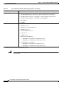
Site Log
We recommend that you maintain a Site Log to record all actions relevant to the system. Site Log entries
might include the following:
•
Installation—Print a copy of the Installation Checklist and insert it into the Site Log.
•
Upgrades and maintenance—Use the Site Log to record ongoing maintenance and expansion
history. Update the Site Log to reflect the following:
– Configuration changes
– Maintenance schedules, requirements, and procedures performed
– Comments, notes, and problems
– Changes and updates to Cisco IOS software
Cisco VG350 Voice Gateway Hardware Installation Guide
OL-25970-01
4-5
Chapter 4
Installing the Cisco VG350 Voice Gateway
Keeping Track–Checklist
Keeping Track–Checklist
We recommend that you use an installation checklist and maintain a Site Log.
Installation Checklist
The Installation Checklist (see Figure 4-1) lists the tasks for installing a Cisco VG350 Voice Gateway.
Print a copy of this checklist and mark the entries as you complete each task. For each Cisco VG350
Voice Gateway, include a copy of the checklist in your Site Log.
Figure 4-1
Installation Checklist
Installation Checklist for site ______________________________________________
Cisco VG name/serial number _____________________________________________
Task
Verified by
Date
Background information placed in Site Log
Environmental specifications verified
Site power voltages verified
Installation site prepower check completed
Required tools available
Additional equipment available
Cisco VG received
Quick start guide received
Regulatory compliance and safety information received
Information packet, warranty card, and Cisco.com card received
Software version verified
Rack, desktop, or wall-mounting of chassis completed
Initial electrical connections established
ASCII terminal attached to console port
Modem attached to console port (for remote configuration)
Signal distance limits verified
Startup sequence steps completed
Initial operation verified
Cisco VG350 Voice Gateway Hardware Installation Guide
4-6
OL-25970-01
Chapter 4
Installing the Cisco VG350 Voice Gateway
Mounting Tools and Equipment
Mounting Tools and Equipment
Obtain the following tools and parts to install a Cisco VG350 Voice Gateway:
•
Standard flat-blade screwdriver as required for attaching brackets to rack or wall
•
Phillips screwdriver for attaching brackets to a Cisco VG350 Voice Gateway
•
Mounting brackets and screws for 24-inch rack, if required:
– Four telco machine screws, for installing the chassis in a rack (use the screw size required by
the rack)
•
Screws and anchors for wall-mounting, if required
– Eight wood screws or other fasteners, for installing the chassis on a wall. An additional starter
screw can be used to facilitate wall-mounting.
•
ESD-preventive wrist strap
In addition, you might need the following external equipment:
•
Console terminal or PC with terminal emulation software
•
PC running terminal emulation software for administrative access
•
Modem for remote access
•
Analog voice RJ-21 cable
•
Ethernet switch
•
Modem for remote configuration
Unpacking and Inspection
Do not unpack the Cisco VG350 until you are ready to install it. If the installation site is not ready, keep
the chassis in its shipping container to prevent accidental damage.
The Cisco VG350, cables, printed publications, and any optional equipment you ordered might be
shipped in more than one container. When you unpack each shipping container, check the packing list
to ensure that you received all the following items:
•
Cisco VG350 Voice Gateway
•
Power cord, 6-foot (1.8-meter)
•
RJ-45-to-DB-25 adapter cable (labeled Console)
•
RJ-45-to-DB-9 adapter cable (labeled Auxiliary)
•
Rack-mounting brackets for 19-inch rack (one pair) with screws for attaching to chassis
•
Chassis guard for wall-mounting applications
•
Grounding lug and fasteners
•
Read Me First for Cisco VG350 Voice Gateway
Inspect all items for shipping damage. If anything appears damaged, or if you encounter problems when
installing or configuring your system, contact a customer service representative. (See the “Obtaining
Documentation” section on page -xv.)
Cisco VG350 Voice Gateway Hardware Installation Guide
OL-25970-01
4-7
Chapter 4
Installing the Cisco VG350 Voice Gateway
Unpacking and Inspection
Cisco VG350 Voice Gateway Hardware Installation Guide
4-8
OL-25970-01
CH A P T E R
5
Powering On the Cisco VG350 Voice Gateway
To power on your Cisco VG350 Voice Gateway, perform the following tasks in the order listed, as
required:
•
Checklist for Power-On, page 5-1
•
Power-On Procedure, page 5-1
•
Troubleshooting, page 5-3
Checklist for Power-On
You can power on a Cisco VG350 Voice Gateway if it meets the requirements described in
Chapter 4, “Installing the Cisco VG350 Voice Gateway”:
•
The chassis is securely mounted.
•
Power cable is connected.
•
Interface cables are connected.
Power-On Procedure
Perform this procedure to power on your Cisco VG350 Voice Gateway, and verify that it goes through
its initialization and self-test. When this is finished, the Cisco VG350 Voice Gateway is ready to
configure.
Warning
This unit might have more than one power supply connection. All connections must be removed to
de-energize the unit. Statement 1028
Warning
Installation of the equipment must comply with local and national electrical codes. Statement 1074
Cisco VG350 Voice Gateway Hardware Installation Guide
OL-25970-01
5-1
Chapter 5
Powering On the Cisco VG350 Voice Gateway
Power-On Procedure
To power on the Cisco VG350 Voice Gateway, perform the following:
Step 1
Power on your terminal or PC, and configure it for 9600 bps, 8 data bits, 1 stop bit, and no parity.
Step 2
Move the Cisco VG350 Voice Gateway power switch to the ON position.
The green LED next to the auxiliary port should come on and the fan should operate. If this does not
happen, see the “Troubleshooting” section on page 5-3.
The following message is displayed at the end of the boot-up messages:
--- System Configuration Dialog --Would you like to enter the initial configuration dialog? [yes/no]:
Step 3
Enter no to proceed with manual configuration using the CLI:
Would you like to enter the initial configuration dialog? [yes/no]: no
Would you like to terminate autoinstall? [yes]
Step 4
Press Return to terminate autoinstall and continue with manual configuration.
Several messages are displayed, ending with a line similar to the following:
...
Copyright (c) 1986-2003 by cisco Systems, Inc.
Compiled <date> <time> by <person>
Step 5
Press Return to bring up the Router> prompt:
...
flashfs[4]: Initialization complete.
Router>
Step 6
Enter privileged EXEC mode:
Router> enable
Router#
Step 7
Note
Continue with the “Troubleshooting” section on page 5-3.
If the rommon 1> prompt appears, your system has booted in ROM monitor mode. For information on the
ROM monitor, refer to the router rebooting and ROM monitor information in the Cisco IOS
Configuration Fundamentals Configuration Guide for your Cisco IOS software release.
Cisco VG350 Voice Gateway Hardware Installation Guide
5-2
OL-25970-01
Chapter 5
Powering On the Cisco VG350 Voice Gateway
Troubleshooting
Troubleshooting
This section describes possible mechanical problems and corrective actions.
Warning
Only trained and qualified personnel should be allowed to install, replace, or service this equipment.
Statement 1030
Warning
No user-serviceable parts inside. Do not open. Statement 1073
If there appears to be a malfunction, first check all cables and connections. If these are in order, see
Table 5-1 for specific troubles and solutions.
For problems with the configuration, refer to Cisco VG350 Voice Gateway Software Configuration
Guide.
Table 5-1
Troubleshooting the Cisco VG350 Voice Gateway
Symptom
Possible Cause
Corrective Action
Power LED and fan are off
Power source switched off
Switch power source on
Faulty power cable
Check/replace power cable
Faulty power source
Check/correct input power
Faulty internal power supply
Contact Cisco1 or your Cisco reseller
Power LED on; fan off
Faulty Cisco VG350
Contact Cisco1 Technical Service Center
or your Cisco reseller
Power LED off; fan on
Faulty Cisco VG350
Contact Cisco1 or your Cisco reseller
No initialization response from Cisco VG350 Faulty modem console terminal
Unit shuts off after operating for some time
Console screen display freezes
Check/replace modem/terminal
Faulty cabling to terminal
Check/replace cable
Faulty Cisco VG350
Contact Cisco1 or your Cisco reseller
Overheating
Check ventilation
Faulty Cisco VG350
Contact Cisco1 or your Cisco reseller
Console fault
Reset/replace console
Software error
Repeat power-on procedure
Faulty Cisco VG350
Contact Cisco1 or your Cisco reseller
1. See the “Obtaining Technical Assistance” section on page xvi.
Cisco VG350 Voice Gateway Hardware Installation Guide
OL-25970-01
5-3
Chapter 5
Powering On the Cisco VG350 Voice Gateway
Troubleshooting
Cisco VG350 Voice Gateway Hardware Installation Guide
5-4
OL-25970-01
A P P E N D I X
A
Cable Specifications and Information
This appendix provides the connector and pinout information you need for making or purchasing cables
used with Cisco VG350 Voice Gateway. To order cables from Cisco, see the “Obtaining Technical
Assistance” section on page xvi. This appendix contains the following sections:
•
Console and Auxiliary Port Cables and Pinouts, page A-1
•
Gigabit Ethernet Port Pinouts (RJ-45), page A-5
•
Analog Voice Multiport Pinouts (RJ-21X/CA21A), page A-6
The following list shows you which table to see for pinout information:
Cisco VG350 Voice Gateway Port and Connection Type
Pinout Information
Console Port to PC—Cable Pinouts (RJ-45 to DB-9)
Table A-1 on page A-2
Console Port to ASCII Terminal—Cable Pinouts (RJ-45 to DB-25)
Table A-2 on page A-3
Auxiliary Port to Modem—Cable Pinouts (RJ-45 to DB-25)
Table A-3 on page A-4
Alternative Terminal and Modem Connections
Table A-4 on page A-4
Gigabit Ethernet Port Pinouts (RJ-45)
Table A-5 on page A-5
Console and Auxiliary Port Cables and Pinouts
Your Cisco VG350 Voice Gateway comes with the cable and adapters you need to connect a PC, an
ASCII terminal, or a modem to your Cisco VG350 Voice Gateway. The cable kit includes:
•
RJ-45-to-RJ-45 rollover cable
•
RJ-45-to-DB-9 adapter cable for console connection
•
RJ-45-to-DB-25 adapter cable for modem connection
The following illustrations and tables provide cable pinout information:
•
Console port to a PC—See Table A-1 and Table A-4
•
Console port to an ASCII terminal—See Table A-2 and Table A-4
•
Auxiliary port to a modem—See Table A-3 and Table A-4
The console port is configured as data communications equipment (DCE); the auxiliary port is
configured as data terminal equipment (DTE). Both are asynchronous serial ports and use RJ-45
connectors.
Cisco VG350 Voice Gateway Hardware Installation Guide
OL-25970-01
A-1
Appendix A
Cable Specifications and Information
Console and Auxiliary Port Cables and Pinouts
Console Port to PC
Figure A-1 shows the RJ-45-to-RJ-45 rollover cable assembly and the RJ-45-to-DB-9 female DTE
adapter (labeled TERMINAL); Table A-1 lists the pinouts.
Figure A-1
Console Port to PC—Cable and Adapter
RJ-45-to-DB-9 female adapter
9
TERM INAL
RJ-45 cable
Table A-1
1
6
1
Console Port to PC—Cable Pinouts (RJ-45 to DB-9)
Console Port
(DCE, RJ-45)
RJ-45-to-RJ-45
Rollover Cable
RJ-45-to-DB-9
Adapter “TERMINAL”
PC Port
(DTE, DB-9)
Signal
RJ-45 Pin
RJ-45 Pin
RJ-45 Pin
DB-9 Pin
Signal
8
8
8
CTS
1
RTS
1
DTR
2
7
7
6
DSR
TxD
3
6
6
2
RxD
GND
4
5
5
5
GND
GND
5
4
4
5
GND
RxD
6
3
3
3
TxD
DSR
7
2
2
4
DTR
1
1
7
RTS
CTS
H11192
8
5
8
1
1. Pin 1 is connected to pin 8 inside the Cisco VG350 Voice Gateway.
Cisco VG350 Voice Gateway Hardware Installation Guide
A-2
OL-25970-01
Appendix A
Cable Specifications and Information
Console and Auxiliary Port Cables and Pinouts
Console Port to ASCII Terminal
Figure A-2 shows the RJ-45-to-RJ-45 rollover cable assembly and the RJ-45-to-DB-25 female DTE
adapter (labeled TERMINAL); Table A-2 lists the pinouts.
Figure A-2
Console Port to ASCII Terminal—Cable and Adapter
RJ-45-to-DB-25 female adapter
25
13
1
8
1
14
H11193
TERMINAL
CAB-500DTF
RJ-45 cable
Table A-2
Console Port to ASCII Terminal—Cable Pinouts (RJ-45 to DB-25)
Console Port
(DCE, RJ-45)
RJ-45-to-RJ-45
Rollover Cable
RJ-45-to-DB-25
Adapter “TERMINAL”
Terminal Port
(DTE, DB-25)
Signal
RJ-45 Pin
RJ-45 Pin
RJ-45 Pin
DB-25 Pin
Signal
8
8
5
CTS
1
RTS
1
DTR
2
7
7
6
DSR
TxD
3
6
6
3
RxD
GND
4
5
5
7
GND
GND
5
4
4
7
GND
RxD
6
3
3
2
TxD
DSR
7
2
2
20
DTR
1
1
4
RTS
CTS
8
1
1. Pin 1 is connected to pin 8 inside the Cisco VG350 Voice Gateway.
Cisco VG350 Voice Gateway Hardware Installation Guide
OL-25970-01
A-3
Appendix A
Cable Specifications and Information
Console and Auxiliary Port Cables and Pinouts
Auxiliary Port to Modem
Figure A-3 shows the RJ-45-to-RJ-45 rollover cable assembly and the RJ-45-to-DB-25 male DCE
adapter (labeled MODEM); Table A-3 lists the pinouts.
Figure A-3
Auxiliary Port to Modem—Cable and Adapter
RJ-45-to-DB-25 male adapter
14
1
MODEM
CAB-5MODCM
8
13
H11194
RJ-45 cable
1
25
Table A-3
Auxiliary Port to Modem—Cable Pinouts (RJ-45 to DB-25)
Auxiliary Port
(DTE, RJ-45)
RJ-45-to-RJ-45
Rollover Cable
RJ-45-to-DB-25
Adapter “MODEM”
Modem Port
(DCE, DB-25)
Signal
RJ-45 Pin
RJ-45 Pin
RJ-45 Pin
DB-25 Pin
Signal
RTS
1
8
8
4
RTS
DTR
2
7
7
20
DTR
TxD
3
6
6
2
TxD
GND
4
5
5
7
GND
GND
5
4
4
7
GND
RxD
6
3
3
3
RxD
DSR
7
2
2
8
DCD
CTS
8
1
1
5
CTS
Alternative Connections to Terminal and Modem
Your Cisco VG350 Voice Gateway ships with an RJ-45-to-RJ-45 rollover cable and two adapters for
connection to a PC, a terminal, or a modem. If you want to use an RJ-45 straight-through cable or other
adapters, see Table A-4 for usable cable and adapter combinations.
Table A-4
Alternative Terminal and Modem Connections
Cisco VG350 Port
Connection
RJ-45 Cable Type
Adapter
Console port to PC
Straight-through
DCE, DB-9 female
Auxiliary port to modem
Rollover
1
Straight-through
DCE2, DB-25, male
DTE2, DB-25, male
1. An octal cable or RJ-45 breakout cable is equivalent to a rollover cable.
2. Modify the DB-25 adapter by removing the wire in pin 6 and placing it in the pin 8 position.
Cisco VG350 Voice Gateway Hardware Installation Guide
A-4
OL-25970-01
Appendix A
Cable Specifications and Information
Gigabit Ethernet Port Pinouts (RJ-45)
Gigabit Ethernet Port Pinouts (RJ-45)
Figure A-4 shows the RJ-45 connector wiring for the Gigabit Ethernet cable; Figure A-4 lists the
pinouts.
Note
Pinout shown is for category 3, 4, or 5 10/100BASE-T connection to an Gigabit Ethernet switch.
Figure A-4
8
H11421
1
RJ-45 Connector Wiring
Table A-5
Gigabit Ethernet Port Pinouts (RJ-45)
Pin1
Signal
1
TX+
2
TX–
3
RX+
4
–
5
–
6
RX–
7
–
8
–
1. Any pin not referenced is not connected.
Cisco VG350 Voice Gateway Hardware Installation Guide
OL-25970-01
A-5
Appendix A
Cable Specifications and Information
Analog Voice Multiport Pinouts (RJ-21X/CA21A)
Analog Voice Multiport Pinouts (RJ-21X/CA21A)
Figure A-5 shows the RJ-21 connector wiring for the cable used for the multiport analog voice interface.
Figure A-5
RJ-21 Connector Wiring
25
26
50
36484
1
RJ-21 cable
RJ-21 connector
Table A-6 lists the pinouts for the RJ-21 connector.
Table A-6
RJ-21 Connector Pinouts
Port
Number
Connector Pin
Number
Signal
Port
Number
Connector Pin
Number
Signal
1
1
26
Ring
Tip
13
13
38
Ring
Tip
2
2
27
Ring
Tip
14
14
39
Ring
Tip
3
3
28
Ring
Tip
15
15
40
Ring
Tip
4
4
29
Ring
Tip
16
16
41
Ring
Tip
5
5
30
Ring
Tip
17
17
42
Ring
Tip
6
6
31
Ring
Tip
18
18
43
Ring
Tip
7
7
32
Ring
Tip
19
19
44
Ring
Tip
8
8
33
Ring
Tip
20
20
45
Ring
Tip
9
9
34
Ring
Tip
21
21
46
Ring
Tip
10
10
35
Ring
Tip
22
22
47
Ring
Tip
11
11
36
Ring
Tip
23
23
48
Ring
Tip
Cisco VG350 Voice Gateway Hardware Installation Guide
A-6
OL-25970-01
Appendix A
Cable Specifications and Information
Analog Voice Multiport Pinouts (RJ-21X/CA21A)
Table A-6
RJ-21 Connector Pinouts (continued)
Port
Number
Connector Pin
Number
Signal
Port
Number
Connector Pin
Number
Signal
12
12
37
Ring
Tip
24
24
49
Ring
Tip
—
—
—
—
25, 50, 51, 52
GND
Cisco VG350 Voice Gateway Hardware Installation Guide
OL-25970-01
A-7