1
Cisco SFS 3012R Multifabric Server Switch
Hardware Installation Guide
Release 2.8.0
Corporate Headquarters
Cisco Systems, Inc.
170 West Tasman Drive
San Jose, CA 95134-1706
USA
http://www.cisco.com
Tel: 408 526-4000
800 553-NETS (6387)
Fax: 408 526-4100
Text Part Number: OL-11187-01
THE SPECIFICATIONS AND INFORMATION REGARDING THE PRODUCTS IN THIS MANUAL ARE SUBJECT TO CHANGE WITHOUT NOTICE. ALL
STATEMENTS, INFORMATION, AND RECOMMENDATIONS IN THIS MANUAL ARE BELIEVED TO BE ACCURATE BUT ARE PRESENTED WITHOUT
WARRANTY OF ANY KIND, EXPRESS OR IMPLIED. USERS MUST TAKE FULL RESPONSIBILITY FOR THEIR APPLICATION OF ANY PRODUCTS.
THE SOFTWARE LICENSE AND LIMITED WARRANTY FOR THE ACCOMPANYING PRODUCT ARE SET FORTH IN THE INFORMATION PACKET THAT
SHIPPED WITH THE PRODUCT AND ARE INCORPORATED HEREIN BY THIS REFERENCE. IF YOU ARE UNABLE TO LOCATE THE SOFTWARE LICENSE
OR LIMITED WARRANTY, CONTACT YOUR CISCO REPRESENTATIVE FOR A COPY.
The following information is for FCC compliance of Class A devices: This equipment has been tested and found to comply with the limits for a Class A digital device, pursuant
to part 15 of the FCC rules. These limits are designed to provide reasonable protection against harmful interference when the equipment is operated in a commercial
environment. This equipment generates, uses, and can radiate radio-frequency energy and, if not installed and used in accordance with the instruction manual, may cause
harmful interference to radio communications. Operation of this equipment in a residential area is likely to cause harmful interference, in which case users will be required
to correct the interference at their own expense.
The following information is for FCC compliance of Class B devices: The equipment described in this manual generates and may radiate radio-frequency energy. If it is not
installed in accordance with Cisco’s installation instructions, it may cause interference with radio and television reception. This equipment has been tested and found to
comply with the limits for a Class B digital device in accordance with the specifications in part 15 of the FCC rules. These specifications are designed to provide reasonable
protection against such interference in a residential installation. However, there is no guarantee that interference will not occur in a particular installation.
Modifying the equipment without Cisco’s written authorization may result in the equipment no longer complying with FCC requirements for Class A or Class B digital
devices. In that event, your right to use the equipment may be limited by FCC regulations, and you may be required to correct any interference to radio or television
communications at your own expense.
You can determine whether your equipment is causing interference by turning it off. If the interference stops, it was probably caused by the Cisco equipment or one of its
peripheral devices. If the equipment causes interference to radio or television reception, try to correct the interference by using one or more of the following measures:
• Turn the television or radio antenna until the interference stops.
• Move the equipment to one side or the other of the television or radio.
• Move the equipment farther away from the television or radio.
• Plug the equipment into an outlet that is on a different circuit from the television or radio. (That is, make certain the equipment and the television or radio are on circuits
controlled by different circuit breakers or fuses.)
Modifications to this product not authorized by Cisco Systems, Inc. could void the FCC approval and negate your authority to operate the product.
The Cisco implementation of TCP header compression is an adaptation of a program developed by the University of California, Berkeley (UCB) as part of UCB’s public
domain version of the UNIX operating system. All rights reserved. Copyright © 1981, Regents of the University of California.
NOTWITHSTANDING ANY OTHER WARRANTY HEREIN, ALL DOCUMENT FILES AND SOFTWARE OF THESE SUPPLIERS ARE PROVIDED “AS IS” WITH
ALL FAULTS. CISCO AND THE ABOVE-NAMED SUPPLIERS DISCLAIM ALL WARRANTIES, EXPRESSED OR IMPLIED, INCLUDING, WITHOUT
LIMITATION, THOSE OF MERCHANTABILITY, FITNESS FOR A PARTICULAR PURPOSE AND NONINFRINGEMENT OR ARISING FROM A COURSE OF
DEALING, USAGE, OR TRADE PRACTICE.
IN NO EVENT SHALL CISCO OR ITS SUPPLIERS BE LIABLE FOR ANY INDIRECT, SPECIAL, CONSEQUENTIAL, OR INCIDENTAL DAMAGES, INCLUDING,
WITHOUT LIMITATION, LOST PROFITS OR LOSS OR DAMAGE TO DATA ARISING OUT OF THE USE OR INABILITY TO USE THIS MANUAL, EVEN IF CISCO
OR ITS SUPPLIERS HAVE BEEN ADVISED OF THE POSSIBILITY OF SUCH DAMAGES.
Any Internet Protocol (IP) addresses used in this document are not intended to be actual addresses. Any examples, command display output, and figures included in the
document are shown for illustrative purposes only. Any use of actual IP addresses in illustrative content is unintentional and coincidental.
Cisco SFS 3012R Multifabric Server Switch Hardware Installation Guide
© 2006 Cisco Systems, Inc. All rights reserved.
C ON T E N T S
Preface
vii
Audience
vii
Organization
vii
Conventions viii
Statement 1071—Warning Definition
Related Documentation
ix
xiv
Obtaining Documentation xv
Cisco.com xv
Product Documentation DVD xv
Ordering Documentation xv
Documentation Feedback
xvi
Cisco Product Security Overview xvi
Reporting Security Problems in Cisco Products
Product Alerts and Field Notices
xvi
xvii
Obtaining Technical Assistance xvii
Cisco Technical Support & Documentation Website
Submitting a Service Request xviii
Definitions of Service Request Severity xviii
Obtaining Additional Publications and Information
CHAPTER
1
Cisco SFS 3012R Server Switch Overview
Introduction
xvii
xix
1-1
1-1
Features 1-2
Performance 1-2
Unified Fabric 1-2
Transparent Topology 1-2
Redundancy and High-Availability
Scalability 1-3
Cisco SFS 3012R Server Switch Chassis
1-2
1-4
Cisco SFS 3012R Server Switch Components 1-5
Controller Modules 1-5
Ethernet and Fibre Channel Gateways 1-7
InfiniBand Switch Modules 1-9
Cisco SFS 3012R Multifabric Server Switch Hardware Installation Guide
OL-11187-01
iii
Contents
Power Supply Modules
Blower Modules 1-11
CHAPTER
2
1-10
Installing and Booting the Cisco SFS 3012R Server Switch
Safety
2-1
2-1
Preparing for Installation
2-3
Installing Cisco SFS 3012R Server Switch Components
2-3
Mounting the Cisco SFS 3012R Server Switch on a Rack
Attaching a Serial Console Cable to a PC or Terminal
2-4
2-8
Booting the Cisco SFS 3012R Server Switch and Configuring Basic Connectivity
Assigning a Static IP Address 2-9
Obtaining an IP Address with DHCP 2-9
Connecting InfiniBand Hosts
2-10
Managing the Cisco SFS 3012R Server Switch
CHAPTER
3
2-12
Installing and Removing Server Switch Field Replaceable Units (FRUs)
Installing a Controller Module
4
3-1
3-2
Adding or Replacing Ethernet or Fibre Channel Gateways
CHAPTER
2-8
Installing an InfiniBand Switch Module
3-4
Removing an InfiniBand Switch Module
3-7
Installing a Power Supply Module
3-7
Removing a Power Supply Module
3-9
Installing a Blower Module
3-9
Removing a Blower Module
3-11
Viewing and Updating the Software Image
3-3
4-1
Viewing the Software Image Version 4-1
Viewing the Software Image Version with the CLI 4-2
Viewing the Software Image Version with the Element Manager GUI
Updating the Software Image 4-4
Updating the Software Image with the CLI 4-5
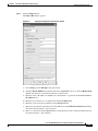
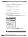
Updating the Software Image with the Element Manager GUI
Deleting a Software Image 4-9
Deleting an Image with the CLI 4-9
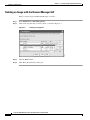
Deleting an Image with the Element Manager GUI
4-3
4-6
4-10
Cisco SFS 3012R Multifabric Server Switch Hardware Installation Guide
iv
OL-11187-01
Contents
CHAPTER
5
Cisco SFS 3012R Server Switch LEDs
5-1
Cisco SFS 3012R Server Switch System Status LED
Power Supply LEDs
5-3
Blower Module LEDs
Controller LEDs
5-2
5-4
5-5
InfiniBand LEDs 5-7
InfiniBand Switch Module LEDs
InfiniBand Port LEDs 5-8
5-7
Fibre Channel LEDs 5-9
Fibre Channel Gateway LEDs 5-9
Fibre Channel Port LEDs 5-10
Ethernet Gateway LEDs 5-11
Ethernet Gateway LEDs 5-12
Ethernet Port LEDs 5-12
APPENDIX
A
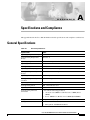
Specifications and Compliance
General Specifications
A-1
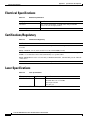
Electrical Specifications
Certifications/Regulatory
Laser Specifications
A-1
A-2
A-2
A-2
INDEX
Cisco SFS 3012R Multifabric Server Switch Hardware Installation Guide
OL-11187-01
v
Contents
Cisco SFS 3012R Multifabric Server Switch Hardware Installation Guide
vi
OL-11187-01
Preface
Audience
The intended audience is the administrator responsible for installing, configuring, and managing server
switch equipment. This administrator should have experience administering similar networking or
storage equipment.
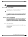
Organization
This publication is organized as follows:
.
Chapter
Title
Description
Chapter 1
Cisco SFS 3012R Server Switch Describes the server switch features
Overview
including its performance, topology,
availability, and scalability. Introduces the
components that populate the chassis.
Chapter 2
Installing and Booting the
Provides step-by-step procedures for
Cisco SFS 3012R Server Switch installing and booting the Cisco SFS 3012R
Server Switch.
Chapter 3
Installing and Removing Server
Switch Field Replaceable Units
(FRUs)
Provides installation and removal
instructions for field replaceable units
(FRUs) such as controller modules,
expansion modules, InfiniBand switch
modules, power modules, and blower
modules.
Chapter 4
Viewing and Updating the
Software Image
Provides step-by-step procedures for
viewing and updating the software image on
all modules in the Cisco SFS 3012R Server
Switch.
Chapter 5
Cisco SFS 3012R Server Switch Explains the LEDs.
LEDs
Appendix A
Specifications and Compliance
Provides details about product
specifications and compliance
certifications.
Cisco SFS 3012R Multifabric Server Switch Hardware Installation Guide
OL-11187-01
vii
Preface
Conventions
Conventions
This document uses the following conventions:
Convention
Description
boldface font
Commands, command options, and keywords are in
boldface. Bold text indicates text that you must enter as-is.
italic font
Arguments in commands for which you supply values are in
italics. Italics not used in commands indicate emphasis.
Menu1 > Menu2 >
Item…
Series indicate a pop-up menu sequence to open a form or
execute a desired function.
[ ]
Elements in square brackets are optional.
{x|y|z}
Alternative keywords are grouped in braces and separated by
vertical bars. Braces can also be used to group keywords
and/or arguments; for example, {interface interface type}.
[x|y|z]
Optional alternative keywords are grouped in brackets and
separated by vertical bars.
string
A nonquoted set of characters. Do not use quotation marks
around the string or the string will include the quotation
marks.
screen
font
Terminal sessions and information the system displays are in
font.
screen
boldface screen
Information you must enter is in boldface
screen
font.
font
italic screen font
Arguments for which you supply values are in italic screen
font.
^
The symbol ^ represents the key labeled Control—for
example, the key combination ^D in a screen display means
hold down the Control key while you press the D key.
< >
Nonprinting characters, such as passwords are in angle
brackets.
[ ]
Default responses to system prompts are in square brackets.
!, #
An exclamation point (!) or a pound sign (#) at the beginning
of a line of code indicates a comment line.
Notes use the following conventions:
Note
Means reader take note. Notes contain helpful suggestions or references to material not covered in
the publication.
Cisco SFS 3012R Multifabric Server Switch Hardware Installation Guide
viii
OL-11187-01
Preface
Conventions
Cautions use the following conventions:
Caution
Means reader be careful. In this situation, you might do something that could result in equipment
damage or loss of data.
Statement 1071—Warning Definition
This section repeats in multiple languages the basic warning appropriate for the Cisco SFS 3012R Server
Switch. Refer to the Regulatory Compliance and Safety Information for the Cisco SFS 7000P, SFS
7008P, and SFS 3012R Switches for translations of all warning messages.
Warning
IMPORTANT SAFETY INSTRUCTIONS
This warning symbol means danger. You are in a situation that could cause bodily injury. Before you
work on any equipment, be aware of the hazards involved with electrical circuitry and be familiar
with standard practices for preventing accidents. Use the statement number provided at the end of
each warning to locate its translation in the translated safety warnings that accompanied this
device.
SAVE THESE INSTRUCTIONS
Waarschuwing
BELANGRIJKE VEILIGHEIDSINSTRUCTIES
Dit waarschuwingssymbool betekent gevaar. U verkeert in een situatie die lichamelijk letsel kan
veroorzaken. Voordat u aan enige apparatuur gaat werken, dient u zich bewust te zijn van de bij
elektrische schakelingen betrokken risico's en dient u op de hoogte te zijn van de standaard
praktijken om ongelukken te voorkomen. Gebruik het nummer van de verklaring onderaan de
waarschuwing als u een vertaling van de waarschuwing die bij het apparaat wordt geleverd, wilt
raadplegen.
BEWAAR DEZE INSTRUCTIES
Varoitus
TÄRKEITÄ TURVALLISUUSOHJEITA
Tämä varoitusmerkki merkitsee vaaraa. Tilanne voi aiheuttaa ruumiillisia vammoja. Ennen kuin
käsittelet laitteistoa, huomioi sähköpiirien käsittelemiseen liittyvät riskit ja tutustu
onnettomuuksien yleisiin ehkäisytapoihin. Turvallisuusvaroitusten käännökset löytyvät laitteen
mukana toimitettujen käännettyjen turvallisuusvaroitusten joukosta varoitusten lopussa näkyvien
lausuntonumeroiden avulla.
SÄILYTÄ NÄMÄ OHJEET
Cisco SFS 3012R Multifabric Server Switch Hardware Installation Guide
OL-11187-01
ix
Preface
Conventions
Attention
IMPORTANTES INFORMATIONS DE SÉCURITÉ
Ce symbole d'avertissement indique un danger. Vous vous trouvez dans une situation pouvant
entraîner des blessures ou des dommages corporels. Avant de travailler sur un équipement, soyez
conscient des dangers liés aux circuits électriques et familiarisez-vous avec les procédures
couramment utilisées pour éviter les accidents. Pour prendre connaissance des traductions des
avertissements figurant dans les consignes de sécurité traduites qui accompagnent cet appareil,
référez-vous au numéro de l'instruction situé à la fin de chaque avertissement.
CONSERVEZ CES INFORMATIONS
Warnung
WICHTIGE SICHERHEITSHINWEISE
Dieses Warnsymbol bedeutet Gefahr. Sie befinden sich in einer Situation, die zu Verletzungen führen
kann. Machen Sie sich vor der Arbeit mit Geräten mit den Gefahren elektrischer Schaltungen und
den üblichen Verfahren zur Vorbeugung vor Unfällen vertraut. Suchen Sie mit der am Ende jeder
Warnung angegebenen Anweisungsnummer nach der jeweiligen Übersetzung in den übersetzten
Sicherheitshinweisen, die zusammen mit diesem Gerät ausgeliefert wurden.
BEWAHREN SIE DIESE HINWEISE GUT AUF.
Avvertenza
IMPORTANTI ISTRUZIONI SULLA SICUREZZA
Questo simbolo di avvertenza indica un pericolo. La situazione potrebbe causare infortuni alle
persone. Prima di intervenire su qualsiasi apparecchiatura, occorre essere al corrente dei pericoli
relativi ai circuiti elettrici e conoscere le procedure standard per la prevenzione di incidenti.
Utilizzare il numero di istruzione presente alla fine di ciascuna avvertenza per individuare le
traduzioni delle avvertenze riportate in questo documento.
CONSERVARE QUESTE ISTRUZIONI
Advarsel
VIKTIGE SIKKERHETSINSTRUKSJONER
Dette advarselssymbolet betyr fare. Du er i en situasjon som kan føre til skade på person. Før du
begynner å arbeide med noe av utstyret, må du være oppmerksom på farene forbundet med
elektriske kretser, og kjenne til standardprosedyrer for å forhindre ulykker. Bruk nummeret i slutten
av hver advarsel for å finne oversettelsen i de oversatte sikkerhetsadvarslene som fulgte med denne
enheten.
TA VARE PÅ DISSE INSTRUKSJONENE
Aviso
INSTRUÇÕES IMPORTANTES DE SEGURANÇA
Este símbolo de aviso significa perigo. Você está em uma situação que poderá ser causadora de
lesões corporais. Antes de iniciar a utilização de qualquer equipamento, tenha conhecimento dos
perigos envolvidos no manuseio de circuitos elétricos e familiarize-se com as práticas habituais de
prevenção de acidentes. Utilize o número da instrução fornecido ao final de cada aviso para
localizar sua tradução nos avisos de segurança traduzidos que acompanham este dispositivo.
GUARDE ESTAS INSTRUÇÕES
Cisco SFS 3012R Multifabric Server Switch Hardware Installation Guide
x
OL-11187-01
Preface
Conventions
¡Advertencia!
INSTRUCCIONES IMPORTANTES DE SEGURIDAD
Este símbolo de aviso indica peligro. Existe riesgo para su integridad física. Antes de manipular
cualquier equipo, considere los riesgos de la corriente eléctrica y familiarícese con los
procedimientos estándar de prevención de accidentes. Al final de cada advertencia encontrará el
número que le ayudará a encontrar el texto traducido en el apartado de traducciones que acompaña
a este dispositivo.
GUARDE ESTAS INSTRUCCIONES
Varning!
VIKTIGA SÄKERHETSANVISNINGAR
Denna varningssignal signalerar fara. Du befinner dig i en situation som kan leda till personskada.
Innan du utför arbete på någon utrustning måste du vara medveten om farorna med elkretsar och
känna till vanliga förfaranden för att förebygga olyckor. Använd det nummer som finns i slutet av
varje varning för att hitta dess översättning i de översatta säkerhetsvarningar som medföljer denna
anordning.
SPARA DESSA ANVISNINGAR
Cisco SFS 3012R Multifabric Server Switch Hardware Installation Guide
OL-11187-01
xi
Preface
Conventions
Aviso
INSTRUÇÕES IMPORTANTES DE SEGURANÇA
Este símbolo de aviso significa perigo. Você se encontra em uma situação em que há risco de lesões
corporais. Antes de trabalhar com qualquer equipamento, esteja ciente dos riscos que envolvem os
circuitos elétricos e familiarize-se com as práticas padrão de prevenção de acidentes. Use o
número da declaração fornecido ao final de cada aviso para localizar sua tradução nos avisos de
segurança traduzidos que acompanham o dispositivo.
GUARDE ESTAS INSTRUÇÕES
Advarsel
VIGTIGE SIKKERHEDSANVISNINGER
Dette advarselssymbol betyder fare. Du befinder dig i en situation med risiko for
legemesbeskadigelse. Før du begynder arbejde på udstyr, skal du være opmærksom på de
involverede risici, der er ved elektriske kredsløb, og du skal sætte dig ind i standardprocedurer til
undgåelse af ulykker. Brug erklæringsnummeret efter hver advarsel for at finde oversættelsen i de
oversatte advarsler, der fulgte med denne enhed.
GEM DISSE ANVISNINGER
Cisco SFS 3012R Multifabric Server Switch Hardware Installation Guide
xii
OL-11187-01
Preface
Conventions
Cisco SFS 3012R Multifabric Server Switch Hardware Installation Guide
OL-11187-01
xiii
Preface
Related Documentation
Related Documentation
For additional information about the Cisco SFS 3012R Server Switch and related products and
interfaces, refer to the following publications:
•
Regulatory Compliance and Safety Information for the Cisco SFS 7000P, SFS 7008P, and
SFS 3012R Switches
•
Cisco SFS 7000 Series Product Family Command Reference
•
Cisco SFS 7000 Series Product Family Element Manager User Guide
Cisco SFS 3012R Multifabric Server Switch Hardware Installation Guide
xiv
OL-11187-01
Preface
Obtaining Documentation
•
Cisco SFS 7000 Series Product Family Chassis Manager User Guide
•
Cisco SFS 7008 InfiniBand and Cisco 3012 Multifabric Server Switches Optional Shelf Kit,
Contents and Installation Guide
•
Cisco SFS 3000 Series Product Family Fibre Channel Gateway User Guide
•
Cisco SFS 3000 Series Product Family Ethernet Gateway User Guide
Obtaining Documentation
Cisco documentation and additional literature are available on Cisco.com. This section explains the
product documentation resources that Cisco offers.
Cisco.com
You can access the most current Cisco documentation at this URL:
http://www.cisco.com/techsupport
You can access the Cisco website at this URL:
http://www.cisco.com
You can access international Cisco websites at this URL:
http://www.cisco.com/public/countries_languages.shtml
Product Documentation DVD
The Product Documentation DVD is a library of technical product documentation on a portable medium.
The DVD enables you to access installation, configuration, and command guides for Cisco hardware and
software products. With the DVD, you have access to the HTML documentation and some of the
PDF files found on the Cisco website at this URL:
http://www.cisco.com/univercd/home/home.htm
The Product Documentation DVD is created and released regularly. DVDs are available singly or by
subscription. Registered Cisco.com users can order a Product Documentation DVD (product number
DOC-DOCDVD= or DOC-DOCDVD=SUB) from Cisco Marketplace at the Product Documentation
Store at this URL:
http://www.cisco.com/go/marketplace/docstore
Ordering Documentation
You must be a registered Cisco.com user to access Cisco Marketplace. Registered users may order
Cisco documentation at the Product Documentation Store at this URL:
http://www.cisco.com/go/marketplace/docstore
If you do not have a user ID or password, you can register at this URL:
http://tools.cisco.com/RPF/register/register.do
Cisco SFS 3012R Multifabric Server Switch Hardware Installation Guide
OL-11187-01
xv
Preface
Documentation Feedback
Documentation Feedback
You can provide feedback about Cisco technical documentation on the Cisco Technical Support &
Documentation site area by entering your comments in the feedback form available in every online
document.
Cisco Product Security Overview
Cisco provides a free online Security Vulnerability Policy portal at this URL:
http://www.cisco.com/en/US/products/products_security_vulnerability_policy.html
From this site, you will find information about how to do the following:
•
Report security vulnerabilities in Cisco products
•
Obtain assistance with security incidents that involve Cisco products
•
Register to receive security information from Cisco
A current list of security advisories, security notices, and security responses for Cisco products is
available at this URL:
http://www.cisco.com/go/psirt
To see security advisories, security notices, and security responses as they are updated in real time, you
can subscribe to the Product Security Incident Response Team Really Simple Syndication (PSIRT RSS)
feed. Information about how to subscribe to the PSIRT RSS feed is found at this URL:
http://www.cisco.com/en/US/products/products_psirt_rss_feed.html
Reporting Security Problems in Cisco Products
Cisco is committed to delivering secure products. We test our products internally before we release them,
and we strive to correct all vulnerabilities quickly. If you think that you have identified a vulnerability
in a Cisco product, contact PSIRT:
•
For emergencies only — [email protected]
An emergency is either a condition in which a system is under active attack or a condition for which
a severe and urgent security vulnerability should be reported. All other conditions are considered
nonemergencies.
•
For nonemergencies — [email protected]
In an emergency, you can also reach PSIRT by telephone:
Tip
•
1 877 228-7302
•
1 408 525-6532
We encourage you to use Pretty Good Privacy (PGP) or a compatible product (for example, GnuPG) to
encrypt any sensitive information that you send to Cisco. PSIRT can work with information that has been
encrypted with PGP versions 2.x through 9.x.
Never use a revoked encryption key or an expired encryption key. The correct public key to use in your
correspondence with PSIRT is the one linked in the Contact Summary section of the Security
Cisco SFS 3012R Multifabric Server Switch Hardware Installation Guide
xvi
OL-11187-01
Preface
Product Alerts and Field Notices
Vulnerability Policy page at this URL:
http://www.cisco.com/en/US/products/products_security_vulnerability_policy.html
The link on this page has the current PGP key ID in use.
If you do not have or use PGP, contact PSIRT to find other means of encrypting the data before sending
any sensitive material.
Product Alerts and Field Notices
Modifications to or updates about Cisco products are announced in Cisco Product Alerts and Cisco Field
Notices. You can receive Cisco Product Alerts and Cisco Field Notices by using the Product Alert Tool
on Cisco.com. This tool enables you to create a profile and choose those products for which you want to
receive information.
To access the Product Alert Tool, you must be a registered Cisco.com user. (To register as a Cisco.com
user, go to this URL: http://tools.cisco.com/RPF/register/register.do) Registered users can access the
tool at this URL: http://tools.cisco.com/Support/PAT/do/ViewMyProfiles.do?local=en
Obtaining Technical Assistance
Cisco Technical Support provides 24-hour-a-day award-winning technical assistance. The
Cisco Technical Support & Documentation website on Cisco.com features extensive online support
resources. In addition, if you have a valid Cisco service contract, Cisco Technical Assistance Center
(TAC) engineers provide telephone support. If you do not have a valid Cisco service contract, contact
your reseller.
Cisco Technical Support & Documentation Website
The Cisco Technical Support & Documentation website provides online documents and tools for
troubleshooting and resolving technical issues with Cisco products and technologies. The website is
available 24 hours a day at this URL:
http://www.cisco.com/techsupport
Access to all tools on the Cisco Technical Support & Documentation website requires a Cisco.com
user ID and password. If you have a valid service contract but do not have a user ID or password, you
can register at this URL:
http://tools.cisco.com/RPF/register/register.do
Note
Use the Cisco Product Identification Tool to locate your product serial number before submitting a
request for service online or by phone. You can access this tool from the Cisco Technical Support &
Documentation website by clicking the Tools & Resources link, clicking the All Tools (A-Z) tab, and
then choosing Cisco Product Identification Tool from the alphabetical list. This tool offers three search
options: by product ID or model name; by tree view; or, for certain products, by copying and pasting
Cisco SFS 3012R Multifabric Server Switch Hardware Installation Guide
OL-11187-01
xvii
Preface
Obtaining Technical Assistance
show command output. Search results show an illustration of your product with the serial number label
location highlighted. Locate the serial number label on your product and record the information before
placing a service call.
Tip
Displaying and Searching on Cisco.com
If you suspect that the browser is not refreshing a web page, force the browser to update the web page
by holding down the Ctrl key while pressing F5.
To find technical information, narrow your search to look in technical documentation, not the entire
Cisco.com website. On the Cisco.com home page, click the Advanced Search link under the Search box
and then click the Technical Support & Documentation radio button.
To provide feedback about the Cisco.com website or a particular technical document, click Contacts &
Feedback at the top of any Cisco.com web page.
Submitting a Service Request
Using the online TAC Service Request Tool is the fastest way to open S3 and S4 service requests. (S3 and
S4 service requests are those in which your network is minimally impaired or for which you require
product information.) After you describe your situation, the TAC Service Request Tool provides
recommended solutions. If your issue is not resolved using the recommended resources, your service
request is assigned to a Cisco engineer. The TAC Service Request Tool is located at this URL:
http://www.cisco.com/techsupport/servicerequest
For S1 or S2 service requests, or if you do not have Internet access, contact the Cisco TAC by telephone.
(S1 or S2 service requests are those in which your production network is down or severely degraded.)
Cisco engineers are assigned immediately to S1 and S2 service requests to help keep your business
operations running smoothly.
To open a service request by telephone, use one of the following numbers:
Asia-Pacific: +61 2 8446 7411
Australia: 1 800 805 227
EMEA: +32 2 704 55 55
USA: 1 800 553 2447
For a complete list of Cisco TAC contacts, go to this URL:
http://www.cisco.com/techsupport/contacts
Definitions of Service Request Severity
To ensure that all service requests are reported in a standard format, Cisco has established severity
definitions.
Severity 1 (S1)—An existing network is “down” or there is a critical impact to your business operations.
You and Cisco will commit all necessary resources around the clock to resolve the situation.
Severity 2 (S2)—Operation of an existing network is severely degraded, or significant aspects of your
business operations are negatively affected by inadequate performance of Cisco products. You and
Cisco will commit full-time resources during normal business hours to resolve the situation.
Cisco SFS 3012R Multifabric Server Switch Hardware Installation Guide
xviii
OL-11187-01
Preface
Obtaining Additional Publications and Information
Severity 3 (S3)—Operational performance of the network is impaired while most business operations
remain functional. You and Cisco will commit resources during normal business hours to restore service
to satisfactory levels.
Severity 4 (S4)—You require information or assistance with Cisco product capabilities, installation, or
configuration. There is little or no effect on your business operations.
Obtaining Additional Publications and Information
Information about Cisco products, technologies, and network solutions is available from various online
and printed sources.
•
The Cisco Online Subscription Center is the website where you can sign up for a variety of
Cisco e-mail newsletters and other communications. Create a profile and then select the
subscriptions that you would like to receive. To visit the Cisco Online Subscription Center,
go to this URL:
http://www.cisco.com/offer/subscribe
•
The Cisco Product Quick Reference Guide is a handy, compact reference tool that includes brief
product overviews, key features, sample part numbers, and abbreviated technical specifications for
many Cisco products that are sold through channel partners. It is updated twice a year and includes
the latest Cisco channel product offerings. To order and find out more about the Cisco Product Quick
Reference Guide, go to this URL:
http://www.cisco.com/go/guide
•
Cisco Marketplace provides a variety of Cisco books, reference guides, documentation, and logo
merchandise. Visit Cisco Marketplace, the company store, at this URL:
http://www.cisco.com/go/marketplace/
•
Cisco Press publishes a wide range of general networking, training, and certification titles. Both new
and experienced users will benefit from these publications. For current Cisco Press titles and other
information, go to Cisco Press at this URL:
http://www.ciscopress.com
•
Internet Protocol Journal is a quarterly journal published by Cisco Systems for engineering
professionals involved in designing, developing, and operating public and private internets and
intranets. You can access the Internet Protocol Journal at this URL:
http://www.cisco.com/ipj
•
Networking products offered by Cisco Systems, as well as customer support services, can be
obtained at this URL:
http://www.cisco.com/en/US/products/index.html
•
Networking Professionals Connection is an interactive website where networking professionals
share questions, suggestions, and information about networking products and technologies with
Cisco experts and other networking professionals. Join a discussion at this URL:
http://www.cisco.com/discuss/networking
•
“What’s New in Cisco Documentation” is an online publication that provides information about the
latest documentation releases for Cisco products. Updated monthly, this online publication is
organized by product category to direct you quickly to the documentation for your products. You
can view the latest release of “What’s New in Cisco Documentation” at this URL:
http://www.cisco.com/univercd/cc/td/doc/abtunicd/136957.htm
Cisco SFS 3012R Multifabric Server Switch Hardware Installation Guide
OL-11187-01
xix
Preface
Obtaining Additional Publications and Information
•
World-class networking training is available from Cisco. You can view current offerings at
this URL:
http://www.cisco.com/en/US/learning/index.html
Cisco SFS 3012R Multifabric Server Switch Hardware Installation Guide
xx
OL-11187-01
1
C H A P T E R
Cisco SFS 3012R Server Switch Overview
The following sections appear in this chapter:
•
Introduction, page 1-1
•
Features, page 1-2
•
Cisco SFS 3012R Server Switch Chassis, page 1-4
•
Cisco SFS 3012R Server Switch Components, page 1-5
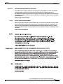
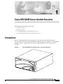
Introduction
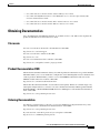
The Cisco SFS 3012R Server Switch provides data center managers with a high-performance,
low-latency interconnect that runs Fibre Channel and Ethernet traffic transparently over an InfiniBand
backplane. Figure 1-1 displays the front of the Cisco SFS 3012R Server Switch (with the bezel
attached).
Cisco SFS 3012R Server Switch Chassis - Front View (Bezel End)
180739
Figure 1-1
Cisco SFS 3012R Multifabric Server Switch Hardware Installation Guide
OL-11187-01
1-1
Chapter 1
Cisco SFS 3012R Server Switch Overview
Features
Features
The Cisco SFS 3012R Server Switch provides unprecedented levels of availability, scalability, and
manageability for deploying server clusters and on-demand computing. Server switch modules provide
up to one terabit of internal bandwidth, and Ethernet or Fibre Channel field-replaceable interface
modules enable up to 72 Ethernet ports or up to 24 Fibre Channel ports and up to 24 InfiniBand ports in
a single chassis.
Performance
Expressly designed to apply networking principles to computing problems, the Cisco SFS 3012R Server
Switch uses a switched InfiniBand fabric to interconnect server resources at 10 Gbps. The combination
of high bandwidth and low latency allows resources to be disaggregated and dynamically reassembled
without the limits of the shared PCI bus.
Unified Fabric
The Cisco SFS 3012R Server Switch integrates storage, server, and networking I/O into one unified
fabric. With only one interface module in each host, you can manage all resources on one fabric and
eliminate the need to install and manage multiple Ethernet, Fibre Channel, and inter-process
communications (IPC) modules. The Cisco SFS 3012R Server Switch aggregates and load balances all
types of I/O, significantly reducing the number of managed ports in your environment and increasing
availability.
Transparent Topology
Based on the Transparent Topology architecture, the Cisco SFS 3012R Server Switch creates virtual IP
and Fibre Channel interfaces on every server, allowing existing IP and storage area network (SAN)
resources to seamlessly extend to server clusters. Using Fibre Channel gateways, SAN management
technologies can access each individual node, enabling critical storage management and security
models, such as Fibre Channel fabric zoning and storage-based logical unit number (LUN) zoning. By
adding Ethernet gateways, IT managers can also enable full Internet Protocol (IP) connectivity,
extending the value of server clusters to the rest of the enterprise.
Redundancy and High-Availability
The Cisco SFS 3012R Server Switch is architected for full redundancy within a single box. Every
component in the data path can be dual-connected from end to end. For example, a server with a 2-port
Host Channel Adaptor (HCA) can be dual-attached to the two InfiniBand switch modules on the
Cisco SFS 3012R Server Switch. Each gateway is also dual attached to the dual switch module. In turn,
the gateway modules are dual attached to Ethernet or Fibre Channel networks in pairs. With the addition
of centralized load balancing and port aggregation, Ethernet and Fibre Channel uplink connections can
be trunked and load balanced, allowing the Cisco SFS 3012R Server Switch to reroute around failures.
Each independently removable component is hot-swappable.
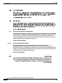
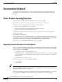
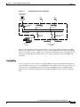
Figure 1-2 shows the internal Cisco SFS 3012R Server Switch architecture. Components within the
dotted line reside within the Cisco SFS 3012R Server Switch chassis.
Cisco SFS 3012R Multifabric Server Switch Hardware Installation Guide
1-2
OL-11187-01
Chapter 1
Cisco SFS 3012R Server Switch Overview
Features
Figure 1-2
Fully Redundant System Architecture
Management
workstation
Host
Controller
cards
IB switch
Host
IB switch
InfiniBand backplane
Ethernet
gateway
Ethernet
switches
Fibre Channel
gateways
180741
Server Switch
Fibre Channel
switches
The Cisco SFS 3012R Server Switch can be used in a variety of networking environments, including
database tiers, application tiers, and Web tiers. The Cisco SFS 3012R Server Switch provides 10 Gbps
per port connectivity to servers, 1 Gbps per port connectivity to Ethernet networks, and 2 Gbps per port
connectivity to Fibre Channel networks. You can also aggregate uplinks for greater bandwidth and
redundancy.
Scalability
You can populate the cable end of the Cisco SFS 3012R Server Switch with additional Fibre Channel
gateways, Ethernet gateways, and a second InfiniBand switch module to increase the port count of your
server switch. A second InfiniBand switch module adds 12 InfiniBand ports. Each additional Fibre
Channel gateway adds 2 Fibre Channel ports. Each additional Ethernet gateway adds 4 or 6 Ethernet
ports.
Cisco SFS 3012R Multifabric Server Switch Hardware Installation Guide
OL-11187-01
1-3
Chapter 1
Cisco SFS 3012R Server Switch Overview
Cisco SFS 3012R Server Switch Chassis
Cisco SFS 3012R Server Switch Chassis
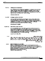
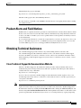
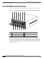
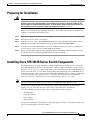
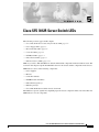
Figure 1-3 displays the back of the Cisco SFS 3012R Server Switch and numbers the slots on the chassis.
Figure 1-3
Cisco SFS 3012R Server Switch Chassis - Back View (cable End) with Slot Numbers
1
3
5
7
9
11
13
15
2
4
6
8
10
12
14
1
Slot 1—Primary Controller module
2 - 13
Slots 2 through 13—Expansion
16 Slot 16—InfiniBand switch module
gateways (Ethernet or Fibre Channel)
14
Slot 14—Standby Controller module
180740
16
15 Slot 15—InfiniBand switch module
The vertical slots at the top of the cable end of the Cisco SFS 3012R Server Switch are numbered 1 to
14 from left to right. The horizontal slots at the bottom of the cable end of the chassis are numbered 15
to 16 from top to bottom. Field replaceable units (FRUs) with interfaces populate the cable end of the
chassis. FRUs such as power supplies and blower modules populate the front of the chassis, behind the
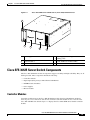
bezel, as shown in Figure 1-4.
Cisco SFS 3012R Multifabric Server Switch Hardware Installation Guide
1-4
OL-11187-01
Chapter 1
Cisco SFS 3012R Server Switch Overview
Cisco SFS 3012R Server Switch Components
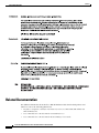
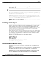
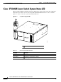
Figure 1-4
Cisco SFS 3012R Server Switch Chassis, Front View, Bezel Removed
5
3
2
180760
4
1
1
Power supply
4
Power supply (shown empty and covered with
blanking panel)
2
Blower module 1
5
System and Blower modules LEDs
3
Blower module 2
Cisco SFS 3012R Server Switch Components
The Cisco SFS 3012R Server Switch components support scalability and high availability. They are all
field replaceable. These components include the following:
•
Controller modules
•
Input/output (I/O) gateways; Fibre Channel and Ethernet
•
InfiniBand switch modules
•
Power supplies
•
Blower modules
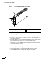
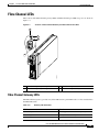
Controller Modules
Controller modules manage the Cisco SFS 3012R Server Switch and provide Ethernet and Serial
Console port access to the server switch. You can install controller modules in slots 1 and 14 of the
Cisco SFS 3012R Server Switch. Figure 1-5 displays the Cisco SFS 3012R Server Switch controller
module.
Cisco SFS 3012R Multifabric Server Switch Hardware Installation Guide
OL-11187-01
1-5
Chapter 1
Cisco SFS 3012R Server Switch Overview
Cisco SFS 3012R Server Switch Components
Figure 1-5
Cisco SFS 3012R Server Switch Controller Module
4
1
180749
3
2
1
Serial console port
3
Ejector lever
2
Management Ethernet port
4
Controller module LEDs
The following points apply to the controller modules:
•
Each Cisco SFS 3012R Server Switch comes with one active controller and, optionally, one warm
standby controller.
•
Upon power-up, the controller in slot 1 becomes the master (active). The controller in slot 14, if
present, becomes the standby.
•
The startup configuration file can be synchronized between the active and the standby controllers.
The Command Line Interface (CLI) prompts users to synchronize the controllers.
•
When the master controller fails or reboots, the standby controller automatically takes over as the
new master. All I/O modules (InfiniBand switch modules, Fibre Channel gateways and Ethernet
gateways) reboot when a failover occurs.
•
Users can force a fail-over with the Element Manager graphic user interface (GUI) or with the CLI.
•
The software upgrade/install process upgrades both the master controller and the standby controller
at the same time. You do not need to upgrade them separately.
•
A subnet manager (SM) runs on each controller module. The SM can manage a single
Cisco SFS 3012R Server Switch or redundant Cisco SFS 3012R Server Switches.
Cisco SFS 3012R Multifabric Server Switch Hardware Installation Guide
1-6
OL-11187-01
Chapter 1
Cisco SFS 3012R Server Switch Overview
Cisco SFS 3012R Server Switch Components
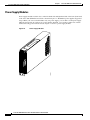
Ethernet and Fibre Channel Gateways
Ethernet and Fibre Channel gateways connect the Cisco SFS 3012R Server Switch and
InfiniBand-connected hosts to IP and Fibre Channel networks. All gateways are dual-connected to the
redundant InfiniBand backplane of the Cisco SFS 3012R Server Switch. Figure 1-6 displays an Ethernet
gateway. Figure 1-7 displays a Fibre Channel gateway.
Figure 1-6
Ethernet Gateway Expansion Module
3
2
180751
1
1
Ethernet ports
2
Ejector handle
3
Ethernet gateway status LEDs
Cisco SFS 3012R Multifabric Server Switch Hardware Installation Guide
OL-11187-01
1-7
Chapter 1
Cisco SFS 3012R Server Switch Overview
Cisco SFS 3012R Server Switch Components
Figure 1-7
Fibre Channel Gateway Expansion Module
4
1
2
180750
3
1
Fibre Channel port 1
3
Ejector handle
2
Fibre Channel port 2
4
Fibre Channel gateway status LEDs
Cisco SFS 3012R Multifabric Server Switch Hardware Installation Guide
1-8
OL-11187-01
Chapter 1
Cisco SFS 3012R Server Switch Overview
Cisco SFS 3012R Server Switch Components
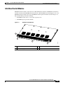
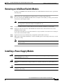
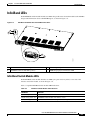
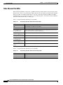
InfiniBand Switch Modules
InfiniBand switch modules connect the Cisco SFS 3012R Server Switch to InfiniBand-attached hosts
and other switches in the InfiniBand network. The Cisco SFS 3012R Server Switch supports one or two
InfiniBand switch modules. The 12-port InfiniBand switch expansion module is shown in Figure 1-8.
The switch module provides the following:
•
4x InfiniBand connections to each of the 12 gateway slots
•
12 InfiniBand ports per switch module
Figure 1-8
InfiniBand Switch Module
4
3
2
1
InfiniBand ports
3
Ejector lever (left)
2
Ejector lever (right)
4
Status LEDs
180766
1
Cisco SFS 3012R Multifabric Server Switch Hardware Installation Guide
OL-11187-01
1-9
Chapter 1
Cisco SFS 3012R Server Switch Overview
Cisco SFS 3012R Server Switch Components
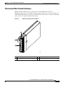
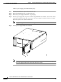
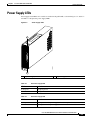
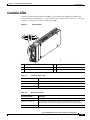
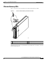
Power Supply Modules
Power supply modules reside in slots on the left-hand side and right-hand side of the front (bezel end)
of the Cisco SFS 3012R Server Switch as shown in Figure 1-4. Redundant power supplies support hot
swaps. When your server switch includes only one power supply, you can add a second power supply
while the chassis runs. If you have two power supplies installed, you can remove either one of them
without removing power from the chassis. Figure 1-9 shows a power supply module.
Power Supply Module
180761
Figure 1-9
Cisco SFS 3012R Multifabric Server Switch Hardware Installation Guide
1-10
OL-11187-01
Chapter 1
Cisco SFS 3012R Server Switch Overview
Cisco SFS 3012R Server Switch Components
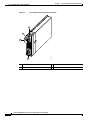
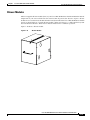
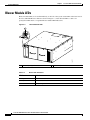
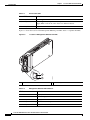
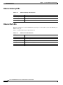
Blower Modules
The hot-swappable blower modules (fans) of your Cisco SFS 3012R Server Switch maintain the internal
temperature of your server switch. You do not need to turn off power to the chassis to replace a blower
module. You access the blower module from the front (bezel end) of the Cisco SFS 3012R Server Switch
chassis as shown in Figure 1-4. Each blower module contains two blowers, so a fully functional system
has four functional blowers. Three blowers must be functional for continuous operation.
Figure 1-10 shows a blower module.
Blower Module
180758
Figure 1-10
Cisco SFS 3012R Multifabric Server Switch Hardware Installation Guide
OL-11187-01
1-11
Chapter 1
Cisco SFS 3012R Server Switch Overview
Cisco SFS 3012R Server Switch Components
Cisco SFS 3012R Multifabric Server Switch Hardware Installation Guide
1-12
OL-11187-01
C H A P T E R
2
Installing and Booting the Cisco SFS 3012R
Server Switch
This chapter explains how to mount your Cisco SFS 3012R Server Switch on a rack, boot the
Cisco SFS 3012R Server Switch, and configure basic services. For advanced configuration information,
refer to the Cisco SFS 7000 Series Product Family Command Reference or the Cisco SFS 7000 Series
Product Family Element Manager User Guide.
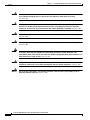
The following sections appear in this chapter:
•
Safety, page 2-1
•
Preparing for Installation, page 2-3
•
Installing Cisco SFS 3012R Server Switch Components, page 2-3
•
Mounting the Cisco SFS 3012R Server Switch on a Rack, page 2-4
•
Attaching a Serial Console Cable to a PC or Terminal, page 2-8
•
Booting the Cisco SFS 3012R Server Switch and Configuring Basic Connectivity, page 2-8
•
Connecting InfiniBand Hosts, page 2-10
•
Managing the Cisco SFS 3012R Server Switch, page 2-12
Safety
Warning
During this procedure, wear grounding wrist straps to avoid ESD damage to the card. Do not directly
touch the backplane with your hand or any metal tool, or you could shock yourself. Statement 94
Warning
Voltage is present on the backplane when the system is operating. To reduce risk of an electric shock,
keep hands and fingers out of the power supply bays and backplane areas. Statement 166
Warning
Read the installation instructions before connecting the system to the power source. Statement 1004
Cisco SFS 3012R Multifabric Server Switch Hardware Installation Guide
OL-11187-01
2-1
Chapter 2
Installing and Booting the Cisco SFS 3012R Server Switch
Safety
Warning
This unit is intended for installation in restricted access areas. A restricted access area can be
accessed only through the use of a special tool, lock and key, or other means of security.
Statement 1017
Warning
This equipment must be grounded. Never defeat the ground conductor or operate the equipment in the
absence of a suitably installed ground conductor. Contact the appropriate electrical inspection
authority or an electrician if you are uncertain that suitable grounding is available. Statement 1024
Warning
Only trained and qualified personnel should be allowed to install, replace, or service this equipment.
Statement 1030
Warning
Ultimate disposal of this product should be handled according to all national laws and regulations.
Statement 1040
Warning
This equipment must be installed and maintained by service personnel as defined by AS/NZS 3260.
Incorrectly connecting this equipment to a general-purpose outlet could be hazardous. The
telecommunications lines must be disconnected 1) before unplugging the main power connector or 2)
while the housing is open, or both. Statement 1043
Warning
This product requires short-circuit (overcurrent) protection, to be provided as part of the building
installation. Install only in accordance with national and local wiring regulations. Statement 1045
Warning
Use of controls, adjustments, or performing procedures other than those specified may result in
hazardous radiation exposure. Statement 1057
Cisco SFS 3012R Multifabric Server Switch Hardware Installation Guide
2-2
OL-11187-01
Chapter 2
Installing and Booting the Cisco SFS 3012R Server Switch
Preparing for Installation
Preparing for Installation
Warning
Two people are required to lift the chassis. Grasp the chassis underneath the lower edge and lift with
both hands. To prevent injury, keep your back straight and lift with your legs, not your back. To prevent
damage to the chassis and components, never attempt to lift the chassis with the handles on the
power supplies or on the interface processors, or by the plastic panels on the front of the chassis.
These handles were not designed to support the weight of the chassis. Statement 5
Prepare for your installation by unpacking the product, and ensuring other necessary components are
available, as described in the following steps.
Step 1
Remove all components from the Cisco SFS 3012R Server Switch shipping container, and identify them.
Step 2
Place the chassis on a secure, clean surface.
Step 3
Verify that you have a Cisco SFS 7008 InfiniBand and Cisco SFS 3012 Multifabric Server Switches
Shelf Kit at hand (ordered and shipped separately, product number SFS-7008P-RKIT).
Step 4
Verify that you have at hand all Ethernet gateways and Fibre Channel gateways that you will need to
increase the port count of your Cisco SFS 3012R Server Switch.
Step 5
Prepare a management workstation (not included), such as a PC running terminal-emulation software
(not included), and a straight-through M/F DB-9 serial cable (included).
Installing Cisco SFS 3012R Server Switch Components
We recommend that you install all Ethernet or Fibre Channel gateway modules before you mount the
Cisco SFS 3012R Server Switch, as described in the “Adding or Replacing Ethernet or Fibre Channel
Gateways” section on page 3-3. These components are not preinstalled in the Cisco SFS 3012R Server
Switch chassis. However, you can add or change modules after mounting the Cisco SFS 3012R Server
Switch chassis in the rack. For details about installing Fibre Channel gateways, see the Cisco SFS 3000
Series Product Family Fibre Channel Gateway User Guide. For details about installing Ethernet
gateways, see the Cisco SFS 3000 Series Product Family Ethernet Gateway User Guide.
Note
All cable connections to Ethernet gateways must use shielded RJ45 CAT5 Ethernet cables.
All other server switch modules are preinstalled in your Cisco SFS 3012R Server Switch before
shipping. You can, if needed, still add or replace these components before mounting the
Cisco SFS 3012R Server Switch chassis. These components include the following:
•
Switch modules
•
Controller modules
•
Power supplies
•
Blower modules
Instructions for installing or replacing these components appear in Chapter 3, “Installing and Removing
Server Switch Field Replaceable Units (FRUs)”.
Cisco SFS 3012R Multifabric Server Switch Hardware Installation Guide
OL-11187-01
2-3
Chapter 2
Installing and Booting the Cisco SFS 3012R Server Switch
Mounting the Cisco SFS 3012R Server Switch on a Rack
Mounting the Cisco SFS 3012R Server Switch on a Rack
Warning
Two people are required to lift the chassis. Grasp the chassis underneath the lower edge and lift with
both hands. To prevent injury, keep your back straight and lift with your legs, not your back. To prevent
damage to the chassis and components, never attempt to lift the chassis with the handles on the
power supplies or on the interface processors, or by the plastic panels on the front of the chassis.
These handles were not designed to support the weight of the chassis. Statement 5
Warning
To prevent bodily injury when mounting or servicing this unit in a rack, you must take special
precautions to ensure that the system remains stable. The following guidelines are provided to ensure
your safety:
• This unit should be mounted at the bottom of the rack if it is the only unit in the rack.
• When mounting this unit in a partially filled rack, load the rack from the bottom to the top with the heaviest
component at the bottom of the rack.
•If the rack is provided with stabilizing devices, install the stabilizers before mounting or servicing the unit in the
rack. Statement 1006
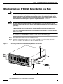
To install the Cisco SFS 3012R Server Switch on a rack, perform the following steps:
Figure 2-1
Step 1
Open the plastic bag that contains the mounting hardware.
Step 2
Attach the rack-mounting brackets to the sides of the chassis with the screws provided, as shown in
Figure 2-1. Use the top and middle holes of the rack-mounting brackets.
Positioning and Fastening the Rack-Mounting Brackets and Shelf Rails
180733
2
1
1
Mounting bracket
2
Shelf rail
Cisco SFS 3012R Multifabric Server Switch Hardware Installation Guide
2-4
OL-11187-01
Chapter 2
Installing and Booting the Cisco SFS 3012R Server Switch
Mounting the Cisco SFS 3012R Server Switch on a Rack
Step 3
Step 4
Attach the shelf rails to either side of the Cisco SFS 3012R Server Switch chassis as follows:
a.
Unpack the shelf assembly kit (ordered and shipped separately).
b.
Identify the shelf rails labeled TS360/SFS 3012.
c.
Attach the rails to the chassis with the four screws provided, as shown in Figure 2-1.
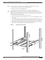
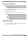
Mount the shelf onto the rack, as shown in Figure 2-2, using the procedure outlined below. (For
additional details about the shelf installation procedure, see “Install the Shelf Kit” in the Cisco SFS 7008
InfiniBand and Cisco 3012 Multifabric Server Switches Optional Shelf Kit, Contents and Installation
Guide, which ships with the shelf assembly.)
a.
Unpack the shelf assembly, and remove the extension brackets.
b.
Verify that the shelf position provides sufficient clearance for the Cisco SFS 3012R Server Switch
and all cables.
c.
Use four screws that fit your rack (not included) to attach the extension brackets to the rack posts at
the rack end at which the bezel end of the chassis will sit. Each bracket must wrap around the inside
of the rack post and attach by its flange to the side of the rack post that faces away from the rack.
d.
Slide the shelf onto the installed extension brackets until the shelf flange makes contact with the
rack posts at the rack end at which the cable end of the chassis will sit.
Attaching the Shelf to the Rack
180734
Figure 2-2
Cisco SFS 3012R Multifabric Server Switch Hardware Installation Guide
OL-11187-01
2-5
Chapter 2
Installing and Booting the Cisco SFS 3012R Server Switch
Mounting the Cisco SFS 3012R Server Switch on a Rack
e.
Note
f.
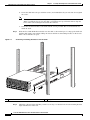
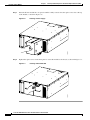
Step 5
Figure 2-3
Secure the shelf end to the post with four screws (not included) that fit your rack, but do not tighten
the screws.
When you install the shelf assembly, do not fully tighten the screws at the cable end of the shelf.
When you slide the chassis onto the shelf, you might need to reposition the shelf to align the
holes in the rack-mounting brackets with the rack holes.
Secure the extension brackets to the shelf with the screws provided. The screw heads must face
inside the shelf.
Slide the Cisco SFS 3012R Server Switch onto the shelf, as shown in Figure 2-3. Engage the shelf rails
with the shelf guides, and continue sliding the chassis until the rack-mounting brackets on the chassis
make contact with the rack posts.
Positioning and Sliding the Chassis onto the Shelf
180735
2
1
1
Shelf rail
Step 6
2
Shelf guide
Adjust the cable end of the shelf that you left loose in Step 4 so that the holes in rack-mounting brackets
align with the holes in the rack.
Cisco SFS 3012R Multifabric Server Switch Hardware Installation Guide
2-6
OL-11187-01
Chapter 2
Installing and Booting the Cisco SFS 3012R Server Switch
Mounting the Cisco SFS 3012R Server Switch on a Rack
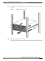
Step 7
Use 4 standard rack screws (not included) to secure the rack-mounting brackets to the rack posts, as shown
in Figure 2-4.
Securing the Chassis to the Rack
180736
Figure 2-4
Step 8
Firmly tighten the shelf screws at the cable end.
Cisco SFS 3012R Multifabric Server Switch Hardware Installation Guide
OL-11187-01
2-7
Chapter 2
Installing and Booting the Cisco SFS 3012R Server Switch
Attaching a Serial Console Cable to a PC or Terminal
Attaching a Serial Console Cable to a PC or Terminal
Step 1
Connect the cable from the serial console port on the controller module to your terminal or management
workstation. Use the straight-through M/F serial cable, which is provided in the package.
For detailed information about how to connect the serial console cable, see the documentation
included with the serial cable kit.
Note
Step 2
Open a terminal emulation window using a program such as HyperTerminal for Windows. Set your
terminal parameters to the following:
– Baud: 9600 bps
– Data Bits: 8
– Parity: None
– Stop Bits: 1
– Flow control: None
Booting the Cisco SFS 3012R Server Switch and Configuring
Basic Connectivity
Warning
Hazardous voltage or energy is present on the backplane when the system is operating. Use caution
when servicing. Statement 1034
To configure basic connectivity, you must power-on the server switch and configure it from a terminal
or workstation through the serial console port. To configure basic Ethernet connectivity, you can apply
a static IP address to the Cisco SFS 3012R Server Switch, or you can configure the chassis to obtain an
IP address from a DHCP server.
With the management console already running an appropriate terminal emulation program as described
in the “Attaching a Serial Console Cable to a PC or Terminal” section on page 2-8, power-on and logon
to your Cisco SFS 3012R Server Switch as described in the following steps:
Step 1
Connect a power cord to your Cisco SFS 3012R Server Switch, and then plug the cord into an
appropriate power source. The Cisco SFS 3012R Server Switch boots.
Step 2
After the system boots, press the Enter key several times to display the CLI login prompt.
Login:
Step 3
Enter super as your user ID and password to log in as a user with administrative privileges.
Login: super
Password: super
SFS-3012R>
Cisco SFS 3012R Multifabric Server Switch Hardware Installation Guide
2-8
OL-11187-01
Chapter 2
Installing and Booting the Cisco SFS 3012R Server Switch
Booting the Cisco SFS 3012R Server Switch and Configuring Basic Connectivity
Assigning a Static IP Address
To configure basic Ethernet connectivity with a static IP address, perform the following steps:
Step 1
Attach an Ethernet cable (not provided) from the management port to the Ethernet router or switch.
Step 2
Enter the enable command.
SFS-3012R> enable
SFS-3012R#
Step 3
Enter the configure command.
SFS-3012R# configure
SFS-3012R(config)#
Step 4
Enter the interface mgmt-ethernet command.
SFS-3012R(config)# interface mgmt-ethernet
Step 5
Enter the IP address of the management port followed by the net mask, as shown in this example:
SFS-3012R(config-if-mgmt-ethernet)# ip address 10.10.0.22 255.255.255.0
Step 6
Set the default gateway of the management port, as shown in this example:
SFS-3012R(config-if-mgmt-ethernet)# gateway 10.10.0.1
Step 7
Enable the management port with the no shutdown command.
SFS-3012R(config-if-mgmt-ethernet)# no shutdown
Step 8
Save the configuration to preserve it between reboots.
SFS-3012R(config-if-mgmt-ethernet)# exit
SFS-3012R(config)# exit
SFS-3012R# copy running-config startup-config
You can now establish a Telent session to your Cisco SFS 3012R Server Switch or enter the IP address
of your Cisco SFS 3012R Server Switch in a web browser to launch Chassis Manager.
Obtaining an IP Address with DHCP
To obtain an IP address dynamically, follow these steps.
Step 1
Attach an Ethernet cable (not provided) from the management port to the Ethernet router or switch.
Step 2
Enter the enable command.
SFS-3012R> enable
SFS-3012R#
Step 3
Enter the configure command.
SFS-3012R# configure
SFS-3012R(config)#
Cisco SFS 3012R Multifabric Server Switch Hardware Installation Guide
OL-11187-01
2-9
Chapter 2
Installing and Booting the Cisco SFS 3012R Server Switch
Connecting InfiniBand Hosts
Step 4
Enter the interface mgmt-ethernet command.
SFS-3012R(config)# interface mgmt-ethernet
Step 5
Enter the addr-option dhcp command to configure the chassis to obtain the IP address from the DHCP
server.
SFS-3012R(config-if-mgmt-ethernet)# addr-option dhcp
Step 6
Enable the management port with the no shutdown command.
SFS-3012R(config-if-mgmt-ethernet)# no shutdown
Step 7
Save the configuration to preserve it between reboots.
SFS-3012R(config-if-mgmt-ethernet)# exit
SFS-3012R(config)# exit
SFS-3012R# copy running-config startup-config
Step 8
Enter the show interface mgmt-ethernet command to determine your IP address, as shown in the
following example:
SFS-3012R# show interface mgmt-ethernet
================================================================================
Mgmt-Ethernet Information
================================================================================
mac-address : 00:05:ad:00:1e:1c
auto-negotiate : enabled
admin-status : up
oper-status : up
ip-addr : 172.29.230.60
mask : 255.255.0.0
gateway-addr : 172.29.230.1
addr-option : static
You can now establish a Telent session to your Cisco SFS 3012R Server Switch or enter the IP address
of your Cisco SFS 3012R Server Switch in a web browser to launch Chassis Manager.
Connecting InfiniBand Hosts
This section provides a brief overview for connecting your InfiniBand hosts. For detailed instructions,
see the documentation for the specific Host Channel Adapter (HCA).
Use InfiniBand cables to connect the HCA in your host to the InfiniBand switch module of your
Cisco SFS 3012R Server Switch. To plug in an InfiniBand cable, push the connector into the interface
until you hear and feel a click. See Figure 2-5 and Figure 2-6.
Cisco SFS 3012R Multifabric Server Switch Hardware Installation Guide
2-10
OL-11187-01
Chapter 2
Installing and Booting the Cisco SFS 3012R Server Switch
Connecting InfiniBand Hosts
Figure 2-5
InfiniBand Cable with Pinch Connector
144960
10
Figure 2-6
InfiniBand Cable with Pull Connector
144961
12
Note
If your host does not provide enough free space around a given InfiniBand port, verify that your
InfiniBand cable connector engages fully. Wiggle your connector back and forth to be sure that both
sides of the connector have locked firmly into place.
To remove a cable with a pinch connector, pinch both sides of the back of the connector, as shown in
Figure 2-7, and pull the connector away from the port.
Cisco SFS 3012R Multifabric Server Switch Hardware Installation Guide
OL-11187-01
2-11
Chapter 2
Installing and Booting the Cisco SFS 3012R Server Switch
Managing the Cisco SFS 3012R Server Switch
Removing a Pinch Connector
13
Press here
Press here
144962
Figure 2-7
To remove a cable with a pull connector, grasp the connector with one hand and push it toward the port,
and then pull the latch away from the port with your other hand and gently wiggle the connector away
from the port, as shown in Figure 2-8.
Figure 2-8
Removing a Pull Connector
Hold here
10
Pull here
144963
Hold here
Managing the Cisco SFS 3012R Server Switch
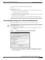
You can manage the Cisco SFS 3012R Server Switch with the following methods:
•
Command Line Interface (CLI)—a text-based interface accessible through a direct serial
connection, Telnet over IP, or SSH over IP.
•
Element Manager (GUI)—A graphical interface installed on a workstation, accessible over IP.
•
Chassis Manager (GUI)—A graphical interface that you access with a web browser.
Refer to the Cisco SFS 7000 Series Product Family Element Manager User Guide, Cisco SFS 7000
Series Product Family Chassis Manager User Guide, and the Cisco SFS 7000 Series Product Family
Command Reference for more information about managing the Cisco SFS 3012R Server Switch.
Cisco SFS 3012R Multifabric Server Switch Hardware Installation Guide
2-12
OL-11187-01
C H A P T E R
3
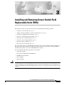
Installing and Removing Server Switch Field
Replaceable Units (FRUs)
This chapter provides step-by-step instructions for performing the following procedures:
•
Installing a Controller Module, page 3-2
•
Adding or Replacing Ethernet or Fibre Channel Gateways, page 3-3
•
Installing an InfiniBand Switch Module, page 3-4
•
Removing an InfiniBand Switch Module, page 3-7
•
Installing a Power Supply Module, page 3-7
•
Removing a Power Supply Module, page 3-9
•
Installing a Blower Module, page 3-9
•
Removing a Blower Module, page 3-11
The components of the Cisco SFS 3012R Server Switch support the scalability and high availability of
the server switch. The sections in this chapter discuss how to use, install, remove, and swap FRUs to
maximize the potential of your Cisco SFS 3012R Server Switch.
You can install the following components in your chassis:
Caution
•
Controller modules
•
I/O gateways (Fibre Channel and Ethernet)
•
InfiniBand switch modules
•
Power supplies
•
Blower modules
Never place your hand inside an empty card or module bay. You should never have cause to place a hand
anywhere inside the Cisco SFS 3012R Server Switch chassis. Unused module bays should always have
a Cisco SFS 3012R Server Switch blanking panel over the bay to ensure proper safety, ventilation, and
cooling.
Cisco SFS 3012R Multifabric Server Switch Hardware Installation Guide
OL-11187-01
3-1
Chapter 3
Installing and Removing Server Switch Field Replaceable Units (FRUs)
Installing a Controller Module
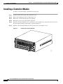
Installing a Controller Module
To install a controller module, perform the following steps:
Step 1
Ground yourself with an approved ground wrist strap.
Step 2
Remove the blanking panel if one resides in the slot.
Step 3
Remove the controller module from any packaging.
Step 4
Extend the ejector lever on the module completely.
Step 5
Insert the controller module into slot 1 (left-most) or slot 14 (right-most) so that the ejector lever sits on
the bottom-left-hand side of the module, as shown in Figure 3-1.
Step 6
Push the controller module firmly into the slot. The ejector lever begins to close.
Inserting the Controller Module
180742
Figure 3-1
Cisco SFS 3012R Multifabric Server Switch Hardware Installation Guide
3-2
OL-11187-01
Chapter 3
Installing and Removing Server Switch Field Replaceable Units (FRUs)
Adding or Replacing Ethernet or Fibre Channel Gateways
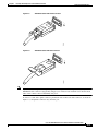
Step 7
Push the ejector lever up until it clicks into place, as shown in Figure 3-2.
Closing the Ejector Lever
180743
Figure 3-2
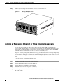
Adding or Replacing Ethernet or Fibre Channel Gateways
You can add, remove, and swap I/O gateways while your Cisco SFS 3012R Server Switch runs.
However, if the software image on your gateway does not match the software image that runs on your
server switch, you must install the correct software on your gateway. For details, refer to the install
command in the Cisco SFS 7000 Series Product Family Command Reference.
Chapter 4, “Viewing and Updating the Software Image” provides instructions for viewing and updating
the software image. To update a single gateway, use the standard installation procedure, but do not reboot
the chassis. You can simply enable and disable the individual gateway to activate the new software
image.
To install a gateway, perform the following steps:
Step 1
Ground yourself using an approved ground wrist strap.
Step 2
Remove the blanking panel if one resides in the slot.
Step 3
Remove the gateway module from any packaging.
Step 4
Extend the ejector lever on the gateway completely.
Step 5
Insert the gateway into an expansion module slot such that the ejector lever sits on the bottom-left-hand
side of the module.
Cisco SFS 3012R Multifabric Server Switch Hardware Installation Guide
OL-11187-01
3-3
Chapter 3
Installing and Removing Server Switch Field Replaceable Units (FRUs)
Installing an InfiniBand Switch Module
Note
You can install gateways in slots 2 (second from left) through 13 (second from right). Populate
your Cisco SFS 3012R Server Switch from left to right.
Step 6
Push the gateway module firmly into the slot. The ejector lever begins to close.
Step 7
Push the ejector lever up until it clicks into place.
Step 8
Follow the procedures in Chapter 4, “Viewing and Updating the Software Image” to update or verify the
software image on the gateway module.
Note
All cable connections to Ethernet gateways must use shielded RJ45 CAT5 Ethernet cables.
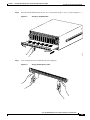
Installing an InfiniBand Switch Module
To install an InfiniBand switch module, perform the following steps:
Step 1
Ground yourself using an approved ground wrist strap.
Step 2
Remove the blanking panel if one resides in the slot with a number 1 Phillips-head screwdriver.
Step 3
Remove the switch module from any packaging.
Step 4
Extend the ejector levers on the left-hand side and on the right-hand side of the switch module
completely.
Step 5
Insert the switch module into slot 15 or slot 16 such that the ejector levers sit on the bottom of the switch
module.
Cisco SFS 3012R Multifabric Server Switch Hardware Installation Guide
3-4
OL-11187-01
Chapter 3
Installing and Removing Server Switch Field Replaceable Units (FRUs)
Installing an InfiniBand Switch Module
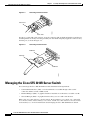
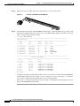
Step 6
Press the switch module firmly into the slot so the fasteners begin to close, as shown in Figure 3-3.
Inserting a Switch Module
180768
Figure 3-3
Step 7
Close both fastener levers simultaneously and completely.
Closing Switch Ejector Levers
133776
Figure 3-4
Cisco SFS 3012R Multifabric Server Switch Hardware Installation Guide
OL-11187-01
3-5
Chapter 3
Installing and Removing Server Switch Field Replaceable Units (FRUs)
Installing an InfiniBand Switch Module
Step 8
Tighten the screws on either side of the switch module to secure it to the chassis.
Securing an InfiniBand Switch Module
180744
Figure 3-5
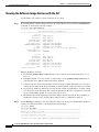
Step 9
Verify that the system image on the InfiniBand switch module is consistent with the image on other cards
in the chassis and update the image, if necessary. Use the show card command to determine the current
image, as shown in the following example:
SFS-3012R# show card all
================================================================================
Card Information
================================================================================
admin
oper
admin
oper
oper
slot type
type
status
status code
-------------------------------------------------------------------------------1* controller
controller
up
up
normal
7
fc2port2G
fc2port2G
up
up
normal
8
fc2port2G
fc2port2G
up
up
normal
14 controller
controller
up
up
standby
15 ib12port4x
ib12port4x
up
down
wrong-image
16 ib12port4x
ib12port4x
up
up
normal
================================================================================
Card Boot Information
================================================================================Pr
boot
boot
boot
slot stage
status
image
-------------------------------------------------------------------------------1
done
success
TopspinOS-2.8.0/build068
7
done
success
TopspinOS-2.8.0/build068
8
done
success
TopspinOS-2.8.0/build068
14 done
success
TopspinOS-2.8.0/build068
15 none
none
TopspinOS-2.8.0/build060
16 done
success
TopspinOS-2.8.0/build068
SFS-3012R#
To interpret the output, examine the information for the slot in which you just installed the InfiniBand
switch module. If the oper status is shown as “down” and the oper-code as “wrong-image” (as shown for
slot 15 in the example), then the module needs to have its image updated.
See Chapter 4, “Viewing and Updating the Software Image” for instructions about updating the software
image on the InfiniBand switch module.
Cisco SFS 3012R Multifabric Server Switch Hardware Installation Guide
3-6
OL-11187-01
Chapter 3
Installing and Removing Server Switch Field Replaceable Units (FRUs)
Removing an InfiniBand Switch Module
Removing an InfiniBand Switch Module
To remove an InfiniBand switch module from the Cisco SFS 3012R Server Switch chassis, perform the
following steps:
Step 1
Make sure the Cisco SFS 3012R Server Switch chassis is securely seated in the rack.
Step 2
If you are removing the InfiniBand module from slot 16 (the lower module), you must power down the
chassis before removing the module.
Note
The InfiniBand module in slot 16 is not hot-swappable. The InfiniBand module in slot 15 is
hot-swappable if a functional module is installed in slot 16.
Step 3
Properly ground yourself to avoid potential electrostatic discharge and damage to the module.
Step 4
Facing the cable end of the Cisco SFS 3012R Server Switch chassis, unfasten both screws on the
InfiniBand switch module.
Loosen the screws until you are sure the module is no longer attached to the chassis. Do not attempt to
remove the screws from the module.
Step 5
Open both ejector levers simultaneously, and pull the switch module toward you.
Step 6
Either replace the module immediately or install a blanking panel over the empty chassis bay to ensure
appropriate cooling.
Note
The blanking panel is a flat sheet of metal with the same dimensions as the InfiniBand switch
module faceplate.
Installing a Power Supply Module
Warning
Hazardous voltage or energy is present on the backplane when the system is operating. Use caution
when servicing. Statement 1034
Caution
Never place your hand inside an empty module bay or anywhere inside the Cisco SFS 3012R Server
Switch.
Caution
Unused module bays should always have a switch filler panel over the bay to ensure proper safety,
ventilation, and cooling.
Cisco SFS 3012R Multifabric Server Switch Hardware Installation Guide
OL-11187-01
3-7
Chapter 3
Installing and Removing Server Switch Field Replaceable Units (FRUs)
Installing a Power Supply Module
To insert a power supply, perform the following steps:
Step 1
Ground yourself using an approved ground wrist strap.
Step 2
Remove the blanking panel if one resides in the slot.
Step 3
Remove the power supply module from any packaging.
Step 4
Insert the power supply into an open slot such that the pull handle sits toward the outside of the chassis,
away from the blower module. The arrow on top of the power supply or underneath the power supply
must always point to the outside of the chassis.
Note
Press the power supply firmly into the chassis.
180762
Step 5
The power supplies should be inserted in opposite directions of each other.
Note
The power socket on the back (cable end) of the Cisco SFS 3012R Server Switch corresponds to
the power supply module on the same side of the server switch.
Cisco SFS 3012R Multifabric Server Switch Hardware Installation Guide
3-8
OL-11187-01
Chapter 3
Installing and Removing Server Switch Field Replaceable Units (FRUs)
Removing a Power Supply Module
Removing a Power Supply Module
Caution
Never place your hand inside an empty module bay or anywhere inside the Cisco SFS 3012R Server
Switch.
To remove the power supply, perform the following steps:
Step 1
Ground yourself using an approved ground wrist strap.
Step 2
Remove the power cord from the power supply.
Step 3
Disengage the power supply by pulling it toward you.
Step 4
Slide the power supply out of the chassis.
Step 5
Either replace the power supply immediately or fasten a blanking panel to the empty chassis bay to
ensure appropriate cooling.
Note
Caution
The blanking panel is a flat sheet of metal with the same dimensions as the power module
faceplate.
Never operate the device without a blanking panel or power supply module in place because
the device might overheat.
Installing a Blower Module
To insert a blower module, perform the following steps:
Step 1
Ground yourself using an approved ground wrist strap.
Step 2
Remove the blower module from any packaging.
Cisco SFS 3012R Multifabric Server Switch Hardware Installation Guide
OL-11187-01
3-9
Chapter 3
Installing and Removing Server Switch Field Replaceable Units (FRUs)
Installing a Blower Module
Step 3
Insert the blower module into an open slot until it is fully seated so that the captive screw sits at the top
of the module, as shown in Figure 3-6.
Inserting a Power Supply
180763
Figure 3-6
Step 4
Tighten the captive screw on the front panel to secure the module to the chassis, as shown in Figure 3-7.
Securing a Blower Module
180764
Figure 3-7
Cisco SFS 3012R Multifabric Server Switch Hardware Installation Guide
3-10
OL-11187-01
Chapter 3
Installing and Removing Server Switch Field Replaceable Units (FRUs)
Removing a Blower Module
Removing a Blower Module
To remove a blower module, perform the following steps:
Step 1
Ground yourself using an approved ground wrist strap.
Step 2
Unfasten the captive screw.
Step 3
Pull the blower module toward you until it completely disengages from the chassis.
Step 4
Insert a replacement blower module into the empty chassis bay to ensure appropriate cooling.
Note
Each blower module contains two blowers for a total of four blowers. The system can tolerate
one out of four blowers failing. When you remove a blower module, you have three minutes to
replace it with a fully-functioning blower module.
Cisco SFS 3012R Multifabric Server Switch Hardware Installation Guide
OL-11187-01
3-11
Chapter 3
Installing and Removing Server Switch Field Replaceable Units (FRUs)
Removing a Blower Module
Cisco SFS 3012R Multifabric Server Switch Hardware Installation Guide
3-12
OL-11187-01
C H A P T E R
4
Viewing and Updating the Software Image
Sections in this chapter provide instructions on the following procedures:
•
Viewing the Software Image Version, page 4-1
•
Updating the Software Image, page 4-4
•
Deleting a Software Image, page 4-9
You can update the software image on all cards in the chassis at once, or on individual cards. You
typically perform these operations when:
Note
•
A new software image is made available by Cisco
•
Checking periodically for updates
•
Adding a new module to your server switch
•
Installing the chassis, if the pre-installed image is already out of date
It is possible to have different versions of software installed on different slots. To update an individual
Fibre Channel or Ethernet gateway, perform the steps as described here, but you do not need to reboot
the chassis. After the copy and installation, you can enable and disable an individual gateway to activate
the new image.
You can view and update the software image using the CLI or with the Element Manager.
Viewing the Software Image Version
This section describes how to obtain and interpret the information you need while updating the software
image. You need to know the following:
•
The version of the software image you have running on each module
•
Whether or not the same version of the software image runs on each module
•
Whether or not the most current software image you have is the most current available
•
Whether or not you have images that you have downloaded but not yet installed
•
Whether or not you have obsolete images that can be deleted
Cisco SFS 3012R Multifabric Server Switch Hardware Installation Guide
OL-11187-01
4-1
Chapter 4
Viewing and Updating the Software Image
Viewing the Software Image Version
Viewing the Software Image Version with the CLI
Use the CLI to view software versions on the chassis as follows:
Step 1
To view the primary software image version for all cards in the chassis, use the show card-inventory
command, as shown in the following example:
SFS-3012R# show card-inventory
================================================================================
Card Resource/Inventory Information
================================================================================
slot-id : 1
used-memory : 77040 (kbytes)
free-memory : 50272 (kbytes)
used-disk-space : 45048 (kbytes)
free-disk-space : 57331 (kbytes)
last-image-source : TopspinOS-2.0.0/build495
primary-image-source : TopspinOS-2.0.0/build495
image : TopspinOS-2.0.0/build495
cpu-descr : PPC 440GP Rev. C - Rev 4.129 (pvr 4012 0481)
fpga-firmware-rev : 6
ib-firmware-rev : 200000000
slot-id
used-memory
free-memory
used-disk-space
free-disk-space
last-image-source
primary-image-source
image
<output truncated>
:
:
:
:
:
:
:
:
10
47676 (kbytes)
34948 (kbytes)
8909 (kbytes)
33361 (kbytes)
TopspinOS-2.0.0/build495
TopspinOS-2.0.0/build495
TopspinOS-2.0.0/build495
Interpret the display as follows:
Step 2
a.
Look for the primary-image-source field for each slot. The slots are identified in Figure 1-3 on
page 1-4.
b.
Determine whether or not any slot has a software image version (primary-image-source) that is
older then the others. This slot will need its image updated.
c.
Compare your most recent image with the most recent image available. Check the Cisco.com site or
your ftp site for details about image availability. Consider updating to the newer image, if available.
d.
If you need to download a new image, note the amount of memory and disk space available. Check
also the file size of the new image that you will download from the Cisco.com website or from the
ftp site and determine whether or not you need to create space.
e.
Examine the files listed in the image field of the display. Any file listed in the image field that is
neither the last-image-source nor the primary-image-source is a candidate for deletion.
Use the dir image command to view all existing boot images on the chassis, and determine whether or
not they are currently installed, as shown in the following example:
SFS-3012R> enable
SFS-3012R# dir image
=============================================================================
Existing Boot-Images on System
=============================================================================
slot date-created size file-name
-------------------------------------------------------------------------------1 Tue Nov 25 18:46:32 2003 30695264 Topspin360-TopspinOS-2.0.0-build212.img
Cisco SFS 3012R Multifabric Server Switch Hardware Installation Guide
4-2
OL-11187-01
Chapter 4
Viewing and Updating the Software Image
Viewing the Software Image Version
1 Tue Nov 25 19:34:08 2003 19228160 TopspinOS-2.0.0/build211
1 Tue Nov 25 19:32:16 2003 15539200 TopspinOS-2.0.0/build212
SFS-3012R#
Interpret the display as follows:
a.
Identify files that have been installed and the files that have been downloaded but not installed:
– A .img file is an image file that is not installed.
– An installed image file has a slash (/) in the name.
b.
Determine if the version of any uninstalled (.img) file is the version that you need to install. If it is,
then you do not need to download it again.
c.
Determine whether any uninstalled file is obsolete. An obsolete file is a candidate for deletion.
Viewing the Software Image Version with the Element Manager GUI
Use the Element Manager GUI to view the software version(s) on the chassis as follows:
Step 1
Launch Element Manager.
Step 2
View the software version of the controller:
a.
Select Maintenance > System Info to view the version of software installed on the controller, as
shown in Figure 4-1.
Figure 4-1
b.
Viewing the Software Image Version of the Controller Module
Note the software image version identified in the Description field and compare it with the most
recent version available on the CCO website or your FTP site. Consider updating to the newer
version, if one is available.
Cisco SFS 3012R Multifabric Server Switch Hardware Installation Guide
OL-11187-01
4-3
Chapter 4
Viewing and Updating the Software Image
Updating the Software Image
Step 3
View the software version on individual cards in the chassis:
a.
Double-click on any module in the main GUI.
b.
Click the Inventory tab. The properties window appears for that module, as shown in Figure 4-2.
Figure 4-2
c.
Viewing Current Image of an Individual Module
View the Current Image Source field. If you find a module that has a different image from the
others, you can update a single module by re-installing the image on the chassis, but reboot only the
module that needs to be updated.
Updating the Software Image
This section provides instructions on how to update the software image using either the CLI or Element
Manager. These procedures include variances depending on whether you are updating the entire chassis
with a new version or updating one gateway to bring it inline with the rest.
Cisco SFS 3012R Multifabric Server Switch Hardware Installation Guide
4-4
OL-11187-01
Chapter 4
Viewing and Updating the Software Image
Updating the Software Image
Updating the Software Image with the CLI
Use the CLI to update the software image as follows:
Step 1
Copy the image to the chassis controller.
Note
Perform this step only if the .img file containing the desired software image is not already on the
controller. This situation usually occurs when updating the entire chassis to a new software
version, although it is possible that the software version already exists on the chassis but has not
yet been installed. If you are updating a single module to bring it into line with the other
modules, then it is usually not necessary to download the .img file again, unless it has been
removed from the controller.
To update the version of software image for the server switch, you need to copy the image to the server
switch. This task can be accomplished through the CLI using FTP and the following copy command
syntax:
copy ftp://<remote-login>:<remote-passwd>@<remote-system>/<filename>.img [<slot-number of
the controller>:]image:<filename>.img
This example shows the copy operation:
SFS-3012R# copy ftp://bob:[email protected]/Topspin-360-TopspinOS-2.1.0-build497.img
image:Topspin-360-2.1.0-build497.img
TopspinOS-2.1.0-build497.img
Step 2
Activate the image. After downloading the image file to the chassis controller, you must install it for it
to become active. The install command installs the specified image file into the system.
Before running the install command, ensure that the following conditions are true:
•
Image files have been copied into the image file-system.
•
The file name must have the .img extension.
•
All cards must have an oper-status of “Up”.
In the privileged-execute mode, enter the following command syntax:
install image:image-file-name.img
This example shows that the install command was successful:
SFS-3012R# install image:Topspin-360-TopspinOS-2.1.0-build497.img
*****************operation completed successfully
Note
Step 3
If you do not have enough available memory to install an additional image, delete an old image. See the
“Deleting a Software Image” section on page 4-9.
Specify the new boot image to be used.
a.
Find the name of your new system image by entering the dir image command. Copy the name of
the new image.
Cisco SFS 3012R Multifabric Server Switch Hardware Installation Guide
OL-11187-01
4-5
Chapter 4
Viewing and Updating the Software Image
Updating the Software Image
b.
Enter boot-config primary-image-source, and then paste the copied image file name, as shown in
the following example:
SFS-3012R# configure
SFS-3012R(config)# boot-config primary-image-source TopspinOS-2.1.0/build497
SFS-3012R(config)# exit
Step 4
Reboot the chassis using the reload command.
Note
You can also use the card shutdown and card no shutdown commands to reboot an individual
module if you do not need to update the entire chassis.
SFS-3012R# reload
Step 5
Save the system configuration when prompted, and confirm that you wish to proceed with the reload, as
shown in the following example:
System configuration has been modified. Save?
[yes(default)/no/*.cfg] yes
Proceed with reload? [confirm]
SFS-3012R#
Step 6
Following reboot, use the show card-inventory command to view the new primary image for all cards
and verify the update.
Updating the Software Image with the Element Manager GUI
Use Element Manager to update the software image as follows:
Step 1
Launch the Element Manager GUI.
Step 2
Select Maintenance > File Management. The File Management window appears.
Note
Perform steps 3 and 4 only if the .img file containing the required image is not on the controller.
This situation usually occurs when updating the entire chassis to a new software version,
although it is possible that the software version already exists on the chassis but has not yet been
installed. If you are updating a single module to bring it into line with the other modules, then
it is usually not necessary to download the .img file again, unless it has been removed from the
controller.
Cisco SFS 3012R Multifabric Server Switch Hardware Installation Guide
4-6
OL-11187-01
Chapter 4
Viewing and Updating the Software Image
Updating the Software Image
Step 3
Click the Import button.
The Import File window appears.
Figure 4-3
Copying an Image File to the Server Switch
a.
Select Image from the File Type drop-down menu.
b.
Click the Remote FTP Sever radio button from the Copy From section (or click the Remote SCP
Server radio button if you will download from an SCP server).
c.
Enter the name or IP address of the FTP server from which to copy the file in the Server Name or
IP Address field.
d.
Enter the network name of a recognized user in the User Name field.
e.
Enter the password for the specified user in the Password field.
f.
Enter the path and name of the image file on the FTP server in the File Path and Name field. Image
file names must include the “.img” extension.
g.
Enter a local file name in the Copy To field for saving the image on the controller module. The local
file name must have a .img extension.
Cisco SFS 3012R Multifabric Server Switch Hardware Installation Guide
OL-11187-01
4-7
Chapter 4
Viewing and Updating the Software Image
Updating the Software Image
Step 4
Click the Copy button to copy the file onto the controller of the sever switch. Wait until the transfer is
complete. The window will automatically refresh to show the latest copied image file.
Step 5
Activate the image. After downloading the image file to the chassis controller, it must be installed to
become active.
Before activating the image, ensure that the following conditions are true:
•
The file name has the .img extension.
•
All cards have an oper-status of “Up”.
Activate the image as follows:
Note
Step 6
a.
Click on the desired .img file in the File Management window.
b.
Click the Install button.
c.
Click Yes to the warning asking if you wish to proceed.
If you do not have enough available memory to install an additional image, delete an old image. See the
“Deleting an Image with the Element Manager GUI” section on page 4-10.
Specify the new boot image to be used.
a.
Select Maintenance-> Boot Config….The Boot Configuration window appears, as shown in
Figure 4-4.
Figure 4-4
Step 7
Specifying the Boot Configuration
b.
Select the new boot image from the Image Source for Next Reboot drop-down menu.
c.
Click the Apply button.
Reboot the chassis.
Note
a.
You can update the software on an individual gateway by enabling and disabling the gateway.
Select Maintenance-> Reboot
Cisco SFS 3012R Multifabric Server Switch Hardware Installation Guide
4-8
OL-11187-01
Chapter 4
Viewing and Updating the Software Image
Deleting a Software Image
b.
Click yes in the Save changes to the system configuration dialog box.
c.
Click Ok in the The chassis will now be rebooted dialog box.
Deleting a Software Image
The following files are candidates for deletion through either the CLI or the Element Manager:
•
.img files. A .img file is an image file that is not installed.
•
An installed image file that is neither the last loaded image (the current image) nor the image
specified during boot configuration as the image source the for the next reboot. These files are
identified by the CLI show card-inventory command as:
– last-image-source
– primary-image-source
These files are specified by the Element Manager as:
– Current Image Version
– Image Source for Next Reboot
Caution
Do not delete the last loaded image or the image specified during boot configuration as the image source
for the next reboot.
Deleting an Image with the CLI
Delete an image (.img file) from the switch using the delete command with the following syntax:
delete [slot-number:]file-system:file
The following example deletes an image file from slot 1. (Slots 1 and 14 can contain controller cards.)
SFS-3012R# delete 1:image:Topspin360-TopspinOS-2.0.0-build488.img
Delete file 14:Topspin360-TopspinOS-2.0.0-build488.img? [yes(default) | no] yes
******
Cisco SFS 3012R Multifabric Server Switch Hardware Installation Guide
OL-11187-01
4-9
Chapter 4
Viewing and Updating the Software Image
Deleting a Software Image
Deleting an Image with the Element Manager GUI
Delete a software image with Element Manager as follows:
Step 1
Select Maintenance > File Management.
Step 2
Click on the .img file that you want to delete, as shown in Figure 4-5.
Figure 4-5
Deleting an Image File
Step 3
Click the Delete button.
Step 4
Click Yes in the Delete file? dialog box.
Cisco SFS 3012R Multifabric Server Switch Hardware Installation Guide
4-10
OL-11187-01
C H A P T E R
5
Cisco SFS 3012R Server Switch LEDs
The following sections appear in this chapter:
•
Cisco SFS 3012R Server Switch System Status LED, page 5-2
•
Power Supply LEDs, page 5-3
•
Blower Module LEDs, page 5-4
•
Controller LEDs, page 5-5
•
InfiniBand LEDs, page 5-7
•
Fibre Channel LEDs, page 5-9
•
Ethernet Gateway LEDs, page 5-11
LEDs on your Cisco SFS 3012R Server Switch and installed components indicate hardware status. The
sections in this chapter explain the LED indications for the chassis and the components in the chassis.
LED indicators exist on the following components:
•
Power supplies
•
Blowers
•
Controller modules
•
InfiniBand switch modules
•
Fibre Channel gateways
•
Ethernet gateways
•
Cisco SFS 3012R Server Switch chassis, bezel end
The LEDs have special significance depending upon the chassis component. This section describes the
LED indicators of each component.
Cisco SFS 3012R Multifabric Server Switch Hardware Installation Guide
OL-11187-01
5-1
Chapter 5
Cisco SFS 3012R Server Switch LEDs
Cisco SFS 3012R Server Switch System Status LED
Cisco SFS 3012R Server Switch System Status LED
The Cisco SFS 3012R Server Switch system status LED appears on the top-left corner of the front (bezel
end) of the server switch. You can view the system status LED with the bezel on or off, as shown in
Figure 5-1. Table 5-1 describes system status LED indications.
Figure 5-1
Location of System LED
180752
1
1
Table 5-1
System status LED
System Status LED Indications
LED State
Indication
Solid green
Chassis runs with no errors.
Solid yellow
A module on the chassis has failed.
Off
No system power.
Cisco SFS 3012R Multifabric Server Switch Hardware Installation Guide
5-2
OL-11187-01
Chapter 5
Cisco SFS 3012R Server Switch LEDs
Power Supply LEDs
Power Supply LEDs
Power supply status LEDs are located above and below the pull handle, as shown in Figure 5-2. Table 5-2
and Table 5-3 interpret the power supply LEDs.
Figure 5-2
Power Supply LEDs
180765
1
2
1
2
DC power supply LED
Table 5-2
AC Power Supply LED
LED State
Indication
Solid green
AC input present.
Off
AC input absent.
Table 5-3
AC power supply LED
DC Power Supply LED
LED State
Indication
Solid green
DC outputs from the power supply fall within regulated limits.
Off
DC outputs from the power supply exceed limits.
Cisco SFS 3012R Multifabric Server Switch Hardware Installation Guide
OL-11187-01
5-3
Chapter 5
Cisco SFS 3012R Server Switch LEDs
Blower Module LEDs
Blower Module LEDs
Blower module LEDs are located immediately to the left of the system status LED on the bezel end of
the Cisco SFS 3012R Server Switch as shown in Figure 5-3. Each blower LED is a dual-color
green/yellow LED. Table 5-4 explains Blower module LED indications.
Figure 5-3
Blower Module LEDs
1
180757
2
1
Blower 1 (the right blower) status LED
Table 5-4
2
Blower 2 (the left blower) status LED.
Blower LED Indications
LED State
Indication
Solid green
Blower runs with no errors.
Solid yellow
A blower has failed.
Off
No system power.
Cisco SFS 3012R Multifabric Server Switch Hardware Installation Guide
5-4
OL-11187-01
Chapter 5
Cisco SFS 3012R Server Switch LEDs
Controller LEDs
Controller LEDs
Controller modules include module status LEDs as well as Management Ethernet port LEDs. The
controller LEDs are shown in Figure 5-4 and described in the callout table below it. Table 5-5, Table 5-6,
and Table 5-7 interpret the controller module status LEDs.
Figure 5-4
1
2
5
6
4
180753
3
Controller LEDs
1
Controller status LED (green)
4
Blower status LED (yellow)
2
Controller status LED (yellow)
5
Power status LED (green)
3
Blower status LED (green)
6
Power status LED (yellow)
Table 5-5
Controller Status LEDs
Controller LED States
Indication
Green on, yellow off
Controller module runs with no errors.
Green off, yellow on
Controller module has a problem that requires user intervention.
Green off, yellow off
No power to the controller module.
Table 5-6
Blower Status LEDs
Blower LED States
Indication
Green on, yellow off
Blowers run with no errors.
Green off, yellow on
Blowers have a problem that requires user intervention. See blower
module LEDs on the front of the chassis for details about the problem.
Green off, yellow off
No power to the blowers.
Cisco SFS 3012R Multifabric Server Switch Hardware Installation Guide
OL-11187-01
5-5
Chapter 5
Cisco SFS 3012R Server Switch LEDs
Controller LEDs
Table 5-7
Power Status LEDs
Power LED States
Indication
Green on, yellow off
Power supplies run with no errors.
Green off, yellow on
Power supplies have a problem that requires user intervention. See Power
supply LEDs on the front of the chassis for additional details.
Green off, yellow off
No power to the chassis.
Figure 5-5 shows the location of the Management Ethernet port LEDs. Table 5-8 explains the LEDs.
Figure 5-5
Location of Management Ethernet Port LEDs
180754
1
2
1
2
Port Link LED
Table 5-8
Port Activity LED
Management Ethernet LED Indications
LED State
Indication
Port Link LED off
No physical link.
Port Link LED solid.
Successful physical link.
Port Activity LED off
No logical link.
Port Activity LED blinking Traffic runs over the port.
Port Activity LED solid
Logical link established.
Cisco SFS 3012R Multifabric Server Switch Hardware Installation Guide
5-6
OL-11187-01
Chapter 5
Cisco SFS 3012R Server Switch LEDs
InfiniBand LEDs
InfiniBand LEDs
Each InfiniBand switch module includes two LEDs that provide status about the module itself and LEDs
that provide information about each InfiniBand port, as shown in Figure 5-6.
Figure 5-6
InfiniBand Switch Module and InfiniBand Port LEDs
1
2
3
180767
4
1
InfiniBand switch module LED (green)
3
InfiniBand port logical link status LED
2
InfiniBand switch module LED (yellow)
4
InfiniBand port physical link status LED
InfiniBand Switch Module LEDs
Each InfiniBand switch module includes two LEDs (one green and one yellow) at one side of the
interface-end of the module, as shown in Figure 5-6.
Table 5-9 explains InfiniBand switch module LED indications.
Table 5-9
Infiniband Switch Module LED Indications
LED States
Indication
Green off, yellow off
No power to the switch module.
Green solid, yellow off
InfiniBand switch module runs with no errors.
Yellow solid, green off
InfiniBand switch module has a problem that requires user intervention.
Cisco SFS 3012R Multifabric Server Switch Hardware Installation Guide
OL-11187-01
5-7
Chapter 5
Cisco SFS 3012R Server Switch LEDs
InfiniBand LEDs
InfiniBand Port LEDs
Two port LEDs (both green) appear next to each InfiniBand port on the switch module, as shown in
Figure 5-6.
Both the top and bottom InfiniBand port LEDs are solid green. The top LED indicates a logical link has
taken place. (A logical link is established when the subnet manager makes a sweep. A logical link must
be established if you are to use the port.) The bottom LED indicates a physical link has occurred. (A
physical link requires that the drivers on the attached InfiniBand host have been installed and are
running).
Table 5-10 explains InfiniBand port LED indications.
Table 5-10
Management Ethernet LED Indications
LED States
Indication
Bottom LED off
No Rx-Character detected.
Bottom LED on
Valid Rx-Character detected.
Bottom LED on, top LED on
Link is OK.
Bottom LED on, top LED off
Logical link not established.
Cisco SFS 3012R Multifabric Server Switch Hardware Installation Guide
5-8
OL-11187-01
Chapter 5
Cisco SFS 3012R Server Switch LEDs
Fibre Channel LEDs
Fibre Channel LEDs
The location of the Fibre Channel gateway LEDs and Fibre Channel port LEDs for port 1 are shown in
Figure 5-7.
Figure 5-7
Location of Fibre Channel Gateway and Fibre Channel Port LEDs
1
2
3
180755
4
1
Fibre Channel gateway LED (yellow)
3
Fibre Channel port status LED
2
Fibre Channel gateway LED (green)
4
Fibre Channel port activity LED
Fibre Channel Gateway LEDs
The Fibre Channel gateway provides one yellow LED and one green LED. Table 5-11 lists and describes
the LED indications.
Table 5-11
Gateway LED Indications
LED States
Indication
Yellow on, green off
Auxiliary power has reached the gateway.
Green on, yellow off
Gateway runs successfully.
Green on, yellow on
An error has occurred.
Cisco SFS 3012R Multifabric Server Switch Hardware Installation Guide
OL-11187-01
5-9
Chapter 5
Cisco SFS 3012R Server Switch LEDs
Fibre Channel LEDs
Fibre Channel Port LEDs
Fibre Channel Port LEDs are adjacent to each Fibre Channel port. They indicate port status and activity.
Each port has a one bi-color, green/yellow, LED to indicate port status. When you enable a Fibre Channel
interface module, and a Fibre Channel device is already connected, the run light (LED) of the Fibre
Channel interface port changes from yellow to green, indicating that a connection has been established
between the Fibre Channel device and the port.
Table 5-12 explains the Fibre Channel port status LED.
Table 5-12
Interpreting the Fibre Channel Port Status LEDs
LED State
Indication
Off
Optic module or cable is not attached.
Solid yellow
A cable is attached, but the port is offline.
Slow pulsing yellow (2
second intervals)
Fiber installed and port is disabled as the result of diagnostics or port access
is denied through CLI or Element Manager.
Fast pulsing yellow
(half-second intervals)
Signal detected but port fault is also detected.
Solid green
The port is online, and a signal is detected.
Slow pulsing green (2
second intervals)
The port is online with a loop-back cable attached or an incompatible device.
Fast pulsing green
(half-second intervals)
The port is online but running some internal diagnostics.
Sporadic flickering
green
The port is online, and packet traffic is detected.
Table 5-13 explains the Fibre Channel port activity LED.
Table 5-13
Interpreting the Fibre Channel Port Activity LEDs
LED State
Indication
Off
1 Gbps
Solid green
2 Gbps
Cisco SFS 3012R Multifabric Server Switch Hardware Installation Guide
5-10
OL-11187-01
Chapter 5
Cisco SFS 3012R Server Switch LEDs
Ethernet Gateway LEDs
Ethernet Gateway LEDs
Figure 5-8 shows the location of the Ethernet gateway LEDs and the Ethernet port LEDs.
Figure 5-8
Location of Ethernet Gateway and Ethernet Port LEDs
1
2
3
180756
4
1
Ethernet gateway LED (yellow)
3
Ethernet port status LED
2
Ethernet gateway LED (green)
4
Ethernet port activity LED
The Ethernet gateway provides one yellow LED and one green LED. Table 5-14 and Table 5-15 list and
describe the LED indications.
Cisco SFS 3012R Multifabric Server Switch Hardware Installation Guide
OL-11187-01
5-11
Chapter 5
Cisco SFS 3012R Server Switch LEDs
Ethernet Gateway LEDs
Ethernet Gateway LEDs
Table 5-14
Ethernet Gateway LED Indications
LED States
Indication
Yellow on, green off
Auxiliary power has reached the gateway.
Green on, yellow off
Gateway runs successfully.
Green on, yellow on
An error has occurred.
Ethernet Port LEDs
Ethernet port LEDs are located on the Ethernet ports. Figure 5-8 shows the location of the Ethernet port
LEDs for one port.
Table 5-15 explains Ethernet port LED indications.
Table 5-15
Ethernet Port LED Indications
LED State
Indication
Status LED off
No physical link.
Status LED solid
Successful physical link.
Activity LED off
No logical link.
Activity LED blinking
Traffic runs over the port.
Activity LED solid
Logical link established but traffic does not yet run.
Cisco SFS 3012R Multifabric Server Switch Hardware Installation Guide
5-12
OL-11187-01
A P P E N D I X
A
Specifications and Compliance
This appendix details the Cisco SFS 3012R Server Switch specifications and compliance certifications.
General Specifications
Table A-1
General Specifications
Specification
Detail
Operating Temperature Range
0 to 35°C
Non-Operating Temperature
Range
-40 to 65 °C
Operating Temperature Gradient 20°C maximum per 60 min
Operating Altitude
0 - 10,000 ft
Non-Operating Alt.
0 - 35,000 ft
Operating Humidity Range
20 to 80%, Non-condensing
Non-Operating Humidity
Ranges
5 to 95%, Non-condensing
Operating Humidity Gradient
Maximum per 60 min: 10%
Non-Operating Humidity
Gradient
0.1, maximum per 60 min
Operating Shock
5G, 11ms half-sine wave
Non-Operating Shock
10G, 11ms half-sine wave
Operating Vibration, Sinusoidal
5G, 5 to 300Hz, 15 minute dwell
Non-Operating Vibration,
Sinusoidal
3 axis with the following parameters
Weight
Management Interfaces
•
“X and Y axis: 0.0004 G 2 / Hz flat from 5-500Hz (0.472
GRMS)
•
Z-axis: 0.0008 G 2 / Hz flat from 5-500Hz (0.629GRMS)
< 95 pounds, fully configured
•
Console RS-232, DB-9 connector
•
Management: 10/100 Ethernet RJ-45
Cisco SFS 3012R Multifabric Server Switch Hardware Installation Guide
OL-11187-01
A-1
Appendix A
Specifications and Compliance
Electrical Specifications
Electrical Specifications
Table A-2
Electrical Specifications
Category
Specification
AC Power
Auto-ranging 90-264VAC, 47-63Hz. Dual independent IEC
connectors, left and right justified.
Power Dissipation
< 650 W maximum
Certifications/Regulatory
Table A-3
Certifications/Regulatory
Certifications
EMC: Class A Radiated and Conducted Emissions per FCC Part 15, subpart B (USA) and ICES-003
(Canada)
Safety: UL60950, 3rd ed. (USA) and CSA 22.2 No. 60950:2000 (Canada)
EMC: Class A Radiated and Conducted Emissions per EN 55022, Harmonics and Flicker tests per EN
61000-3-2,3 and Radiated and Conducted Immunity tests per EN 55024
Safety: EN60950 Declaration of Conformity to EN60950, EN55022, and EN55024 plus the CE mark
on the device.
EMC: Class A Radiated and Conducted Emissions per VCCI V-3/02.04
Laser Specifications
Table A-4
PID
Laser Specifications
Application
SFSXFCHR02F02K9 Fibre Channel
Optical Parameters
*CDRH/IEC Laser Class: I/1
Maximum Data rate: 2.125GB/s
Wavelength: 850 nm
I/O connector:
*Standards used: CDRH - 21CFR Chapter I§ 1040.10; IEC - IEC60825-1:1994
Cisco SFS 3012R Multifabric Server Switch Hardware Installation Guide
A-2
OL-11187-01
I N D EX
controller modules
A
features of
architecture
audience
1-2
installing
vii
LEDs
1-5
3-2 to 3-3
5-5
location of
1-4
slot numbers for
B
basic connectivity
2-8
D
blower modules
features of
installing
LEDs
1-11
DHCP
3-9 to 3-10
2-9
dir image command
5-4
1-5
removing
cisco.com
3-11
4-5
DVD
C
feedback
xvi
obtaining
xv
xv
organization
Cisco SFS 3012R Server Switch
viii
xv
ordering
vii
2-8
components
features of
3-1 to 3-11
removing
3-1 to 3-11
features of
installing
E
1-5 to 1-11
installing
Ethernet conectivity, configuring for
management 2-9 to 2-10
Ethernet gateways
1-1 to 1-3
features of
2-1 to 2-12
installing
5-1 to 5-12
managing
LEDs
2-12
rack mounting
connectivity, basic
2-8
2-8
1-7
3-3 to 3-4
5-11
location of
2-4 to 2-7
configure basic connectivity
console
xv
conventions
boot-config command
LEDs
4-2
documentation
location of
booting
1-4
1-4
slot numbers for
Ethernet port LEDs
1-4
5-12
2-8
console cable
2-8
Cisco SFS 3012R Multifabric Server Switch Hardware Installation Guide
OL-11187-01
IN-1
Index
F
Fibre Channel gateways
features of
installing
LEDs
1-7 to 1-8
port LEDs
5-8
3-7
slot numbers for
3-3 to 3-4
1-4
verifying software for
install command
Fibre Channel port LEDs
5-10
xvii
3-6
4-5
installing the chassis in a rack
2-4
IP address
field replaceable units
features of
1-4
removing
5-9
field notices
location of
dynamic
1-5 to 1-11
installing
3-1 to 3-11
removing
3-1 to 3-11
static
FRU. See field replaceable units
2-9
2-9
L
LEDs
blower module
G
gateways
features of
installing
1-7
3-3 to 3-4
5-4
controller module
5-5
Ethernet gateway
5-11
Ethernet port
5-12
Fibre Channel
5-9
Fibre Channel Port
InfiniBand
H
5-7
InfiniBand port
high availability
1-2
5-10
5-8
power supply
5-3
system status
5-2
I
P
InfiniBand cable
installing
performance
pinch connector
pull connector
power supplies
2-10
features of
2-11
installing
removing
pinch connector
pull connector
installing
LEDs
5-7
1-9
3-4 to 3-6
2-10 to 2-12
1-10
3-7 to 3-8
5-3
location of
2-12
InfiniBand switch modules
features of
LEDs
2-11
InfiniBand hosts, connecting
1-2
removing
1-5
3-9
product alerts
product security
xvii
xvi
publications
obtaining additional
xix
Cisco SFS 3012R Multifabric Server Switch Hardware Installation Guide
IN-2
OL-11187-01
Index
R
racking the chassis
2-4
rack shelf, assembling and installing
redundancy
2-5
1-2
related manuals
xiv
S
safety information
scalability
ix to xiv, 2-1
1-3
security, reporting problems
serial console
xvi
2-8
serial console cable
2-8
service requests
severity, definitions of
submitting
xviii
xviii
shelf, assembling and installing
show card command
2-5
3-6
show card inventory command
4-2
slot numbers, location and use
1-4
software image
deleting with CLI
4-9
deleting with Element Manager
updating with CLI
4-10
4-5
updating with Element Manager
viewing with CLI
4-2
viewing with Element Manager
system architecture
system status LED
4-6 to 4-9
4-3
1-2
5-2
T
technical assistance, obtaining
topology
xvii
1-2
Cisco SFS 3012R Multifabric Server Switch Hardware Installation Guide
OL-11187-01
IN-3
Index
Cisco SFS 3012R Multifabric Server Switch Hardware Installation Guide
IN-4
OL-11187-01