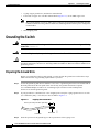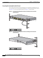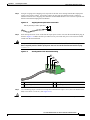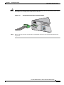
1
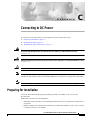
A P P E N D I X
C
Connecting to DC Power
To connect the Cisco ME switch to a DC-input power source, follow these steps:
1.
Preparing for Installation, page C-1
2.
Grounding the Switch, page C-2
3.
Wiring the DC-Input Power Source, page C-5
Warning
This unit is intended for installation in restricted access areas. A restricted access area can be
accessed only through the use of a special tool, lock and key, or other means of security.
Statement 1017
Warning
Before performing any of the following procedures, ensure that power is removed from the DC circuit.
Statement 1003
Caution
Installation of the equipment must comply with local and national electrical codes.
Note
We recommend that you use 18 AWG copper wiring for Network Equipment Building Systems (NEBS)
installation. This guideline follows the standard guidelines for DC power wiring in the Central Office.
Note
You can use the grounding lug to attach a wrist strap for ESD protection during servicing.
Preparing for Installation
Locate the DC terminal block plug, the ground lug, and the two number-10-32 screws in the
DC-switch kit.
Obtain these necessary tools and equipment:
•
Ratcheting torque screwdriver with a Phillips head that exerts up to 15 pound-force inches (lbf-in.)
of pressure.
•
Panduit crimping tool with optional controlled cycle mechanism (model CT-700, CT-720, CT-920,
CT-920CH, CT-930, or CT-940CH).
Cisco ME 3400 Ethernet Access Switch Hardware Installation Guide
OL-7677-02
C-1
Appendix C
Connecting to DC Power
Grounding the Switch
•
6-gauge copper ground wire (insulated or noninsulated).
•
Four leads of copper wire. The DC terminal block (Figure C-11) 12-28 AWG copper wire.
Note
•
We recommend that you use 18 AWG copper wiring for Network Equipment Building Systems
(NEBS) installations. This guideline follows the standard guidelines for DC power wiring in the
Central Office.
Wire-stripping tools.
Grounding the Switch
Warning
This equipment is intended to be grounded. Ensure that the host is connected to earth ground during
normal use. Statement 39
Warning
When installing the unit, always make the ground connection first and disconnect it last. Statement 42
Caution
To make sure that the equipment is reliably connected to earth ground, follow the grounding
procedure instructions, and use a UL-listed lug suitable for number-6 AWG wire and two number-10-32
ground-lug screws.
Preparing the Ground Wire
Before you ground the switch to earth ground, you must prepare the ground wire. Follow these steps.
Make sure to follow any grounding requirements at your site.
Step 1
Locate the ground lug and the two number-10-32 screws. A ground lug and screws are located both on
the front panel and on the rear panel of the switch. Only one ground connection is required.
Use a standard Phillips screwdriver or a ratcheting torque screwdriver with a Phillips head.
Set the screws and the ground lug aside.
Step 2
If your ground wire is insulated, use a wire stripping tool to strip the 6-gauge ground wire to 0.5 inch
(12.7 millimeter [mm]) 0.02 inch (0.5 mm) as shown in Figure C-1.
Figure C-1
Stripping the Ground Wire
Insulation
Step 3
Wire lead
60528
0.5 in. (12.7 mm) ± 0.02 in. (0.5 mm)
Slide the open end of the ground lug over the exposed area of the 6-gauge wire.
Cisco ME 3400 Ethernet Access Switch Hardware Installation Guide
C-2
OL-7677-02
Appendix C
Connecting to DC Power
Grounding the Switch
Step 4
Using a Panduit crimping tool, crimp the ground lug to the 6-gauge wire.
Crimping the Ground Lug
60529
Figure C-2
Use the two number-10-32 screws to attach the ground lug and wire assembly to the rear panel of
the switch.
Step 6
Using a ratcheting torque screwdriver, torque each ground-lug screw to 15 lbf-in. (240 ounce-force
inches [ozf-in.]). Figure C-3 shows how to torque the ground screws on a Cisco ME DC switch.
Torquing Ground-Lug Screws
132854
Figure C-3
Step 5
1
1
Torque to 15 lbf-in.
Cisco ME 3400 Ethernet Access Switch Hardware Installation Guide
OL-7677-02
C-3
Appendix C
Connecting to DC Power
Grounding the Switch
Connecting the Grounding Wire to Earth Ground
Next you must connect the other end of the grounding wire to an appropriate grounding point at your
site or to the telco rack. You can connect the grounding wire to either the front panel ground connector
(see Figure C-4) or the rear panel ground connector (see Figure C-5), but not to both.
Figure C-4
Connecting the Grounding Wire to the Rack (Grounding) from the Front-Panel
Ground Connector
1
SYSTEM
1X
RATING
100
1A-0.5A-240V ~
, 50-60
2
3
4
5
6
7
8
9
10
11
12
13
11X
HZ
13X
CONSOL
E
2X
14
15
16
17
18
19
20
21
22
23
24
23X
Cisco ME
12X
3400 SERIE
S
14X
132856
1
24X
2
1
2
1
Telco rack
Figure C-5
2
Grounding wire
Connecting the Grounding Wire to the Rack (Grounding) from the Rear-Panel
Ground Connector
2
1
Telco rack
2
132857
1
Grounding wire
Cisco ME 3400 Ethernet Access Switch Hardware Installation Guide
C-4
OL-7677-02
Appendix C
Connecting to DC Power
Wiring the DC-Input Power Source
Complete these steps:
Step 1
Remove all paint or oxidation from the rack at the point of the grounding connection.
Step 2
Use a 3/16-inch flat-head screwdriver to loosen the grounding screw on the rack.
Step 3
Connect the wire to a ring lug (large enough for the rack screw to fit through).
Step 4
Use a 3/16-inch flat-head screwdriver and the screw to attach the ring lug to the rack.
Step 5
Tighten the grounding screw on the rack over the ring lug.
Repeat these steps for each switch being installed.
Wiring the DC-Input Power Source
Cisco ME-3400-24TS Switches
Warning
This product relies on the building’s installation for short-circuit (overcurrent) protection. Ensure that
the protective device is rated not greater than:
5 A Statement 1005
Cisco ME-3400G-12CS Switches
Warning
This product relies on the building’s installation for short-circuit (overcurrent) protection. Ensure that
the protective device is rated not greater than:
6 A Statement 1005
All Cisco ME-3400 Switches
Warning
A readily accessible two-poled disconnect device must be incorporated in the fixed wiring.
Statement 1022
Warning
Only trained and qualified personnel should be allowed to install or replace this equipment.
Statement 1030
Caution
You must connect the Cisco ME DC switch only to a DC-input power source that has an input supply
voltage from –36 to –72 VDC. If the supply voltage is not in this range, the switch might not operate
properly or might be damaged.
Cisco ME 3400 Ethernet Access Switch Hardware Installation Guide
OL-7677-02
C-5
Appendix C
Connecting to DC Power
Wiring the DC-Input Power Source
Caution
The Cisco ME-3400G-12CS-DC switch has two DC power supplies. They are labelled PS1 and PS2, and
each power supply has an A and B input. When connecting power to both PS 1 and PS 2, connect only
a single input (A or B) to each power supply).
To wire the switch to a DC-input power source, follow these steps:
Step 1
To ensure that all power is OFF, locate the circuit breaker on the panel board that services the DC circuit,
switch the circuit breaker to the OFF position, and tape the switch handle of the circuit breaker in the
OFF position.
Step 2
Locate the terminal block plug (see Figure C-6).
Terminal Block Plug
60530
Figure C-6
Step 3
Identify the positive and negative feed positions for the terminal block connection. The wiring sequence
is positive to positive and negative to negative for both the A and the B feed wires.
The front panel of the switch identifies the positive and negative positions for both the A and B feed
wires (See Figure C-7.)
Figure C-7
Positive and Negative Positions
SYSTEM
SYSTEM
+
CONSO
LE
132858
+
A
INPUT -3 B
CURRE 6 – -72 V
NT 2 – 1
A
Figure C-7 shows a Cisco ME-3400-24TS-DC. The ME-3400G-12CS-DC switch has two DC power
supplies (labelled PS 1 and PS 2). Each power supply has two inputs (labelled A and B). When
connecting an input to both PS 1 and PS 2, only a single input (A or B) should be connected to each
power supply.
Cisco ME 3400 Ethernet Access Switch Hardware Installation Guide
C-6
OL-7677-02
Appendix C
Connecting to DC Power
Wiring the DC-Input Power Source
Step 4
Using an 18-gauge wire-stripping tool, strip each of the four wires coming from the DC-input power
source to 0.27 inch (6.6 mm) 0.02 inch (0.5 mm). Do not strip more than 0.29 inch (7.4 mm) of
insulation from the wire. Stripping more than the recommended amount of wire can leave exposed wire
from the terminal block plug after installation.
Figure C-8
Stripping the DC-Input Power Source Wire
60531
0.25 in. (6.3 mm) ± 0.02 in. (0.5 mm)
Step 5
Insert the exposed wire of one of the four DC-input power source wires into the terminal block plug, as
shown in Figure C-9. Make sure that you cannot see any wire lead. Only wire with insulation should
extend from the terminal block.
Warning
An exposed wire lead from a DC-input power source can conduct harmful levels of electricity. Be sure
that no exposed portion of the DC-input power source wire extends from the terminal block plug.
Statement 122
Figure C-9
Inserting Wires in the Terminal Block Plug
1
2
3
132849
4
1
Return (positive) Feed A
3
Return (positive) Feed B
2
Supply (negative) Feed A
4
Supply (negative) Feed B
Step 6
Use a ratcheting torque screwdriver to torque the terminal block captive screw (above the installed wire
lead) to 4.5 lbf-in. (72 ozf-in.). (See Figure C-10.)
Caution
Do not overtorque the terminal-block captive screws. The recommended maximum torque is 4.5 lbf-in.
Cisco ME 3400 Ethernet Access Switch Hardware Installation Guide
OL-7677-02
C-7
Appendix C
Connecting to DC Power
Wiring the DC-Input Power Source
Figure C-10
Torquing the Terminal-Block Captive Screws
60533
Torque to 4.5 lbf-in. (72 ozf-in.)
Step 7
Repeat Steps 4 and 5 for the remaining three DC-input power source wires. Figure C-11 shows the
completed wiring of a terminal block plug.
Figure C-11
Completed Wiring of Terminal Block Plug
1
2
3
132850
4
Step 8
1
Return (positive) Feed A
3
Return (positive) Feed B
2
Supply (negative) Feed A
4
Supply (negative) Feed B
Insert the terminal block plug in the terminal block header on the front panel of the switch.
(See Figure C-12).
Cisco ME 3400 Ethernet Access Switch Hardware Installation Guide
C-8
OL-7677-02
Appendix C
Connecting to DC Power
Wiring the DC-Input Power Source
Caution
Secure the wires coming in from the terminal block so that they cannot be disturbed by casual contact.
For example, use tie wraps to secure the wires to the rack.
Figure C-12
Inserting the Terminal Block in the Block Header
SYSTEM
+
CONSO
LE
Step 9
132851
+
A
INPUT -3 B
CURRE 6 – -72 V
NT 2 – 1A
Remove the tape from the circuit-breaker switch handle, and move the circuit-breaker handle to the
on position.
Cisco ME 3400 Ethernet Access Switch Hardware Installation Guide
OL-7677-02
C-9
Appendix C
Connecting to DC Power
Wiring the DC-Input Power Source
Cisco ME 3400 Ethernet Access Switch Hardware Installation Guide
C-10
OL-7677-02