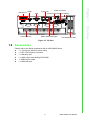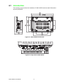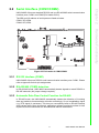
1
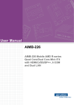
User Manual UNO-3483G Series Intel® Core® i7 Processors Embedded Automation PC, with 1x PCI(e) Extension Slots Copyright The documentation and the software included with this product are copyrighted 2015 by Advantech Co., Ltd. All rights are reserved. Advantech Co., Ltd. reserves the right to make improvements in the products described in this manual at any time without notice. No part of this manual may be reproduced, copied, translated or transmitted in any form or by any means without the prior written permission of Advantech Co., Ltd. Information provided in this manual is intended to be accurate and reliable. However, Advantech Co., Ltd. assumes no responsibility for its use, nor for any infringements of the rights of third parties, which may result from its use. Acknowledgements IBM, PC/ATand VGA are trademarks of International Business Machines Corporation. Intel® is trademarks of Intel Corporation. Microsoft Windows and MS-DOS are registered trademarks of Microsoft Corp. C&T is a trademark of Chips and Technologies, Inc. All other product names or trademarks are properties of their respective owners. This manual applies to the below model which is abbreviated as UNO-3400G series products in this article. UNO-3483G UNO-3483G-374AE UNO3483G36A1501E-T UNO3483G37A1502E-T UNO3483G37A1503E-T Edition 1 Printed in Taiwan UNO-3483G User Manual April 2015 ii Product Warranty (2 years) Advantech warrants to you, the original purchaser, that each of its products will be free from defects in materials and workmanship for two years from the date of purchase. This warranty does not apply to any products which have been repaired or altered by persons other than repair personnel authorized by Advantech, or which have been subject to misuse, abuse, accident or improper installation. Advantech assumes no liability under the terms of this warranty as a consequence of such events. Because of Advantech’s high quality-control standards and rigorous testing, most of our customers never need to use our repair service. If an Advantech product is defective, it will be repaired or replaced at no charge during the warranty period. For outof-warranty repairs, you will be billed according to the cost of replacement materials, service time and freight. Please consult your dealer for more details. If you think you have a defective product, follow these steps: 1. Collect all the information about the problem encountered. (For example, CPU speed, Advantech products used, other hardware and software used, etc.) Note anything abnormal and list any onscreen messages you get when the problem occurs. 2. Call your dealer and describe the problem. Please have your manual, product, and any helpful information readily available. 3. If your product is diagnosed as defective, obtain an RMA (return merchandize authorization) number from your dealer. This allows us to process your return more quickly. 4. Carefully pack the defective product, a fully-completed Repair and Replacement Order Card and a photocopy proof of purchase date (such as your sales receipt) in a shippable container. A product returned without proof of the purchase date is not eligible for warranty service. 5. Write the RMA number visibly on the outside of the package and ship it prepaid to your dealer. Declaration of Conformity CE This product has passed the CE test for environmental specifications when shielded cables are used for external wiring. We recommend the use of shielded cables. This kind of cable is available from Advantech. Please contact your local supplier for ordering information. FCC Class A Note: This equipment has been tested and found to comply with the limits for a Class A digital device, pursuant to part 15 of the FCC Rules. These limits are designed to provide reasonable protection against harmful interference when the equipment is operated in a commercial environment. This equipment generates, uses, and can radiate radio frequency energy and, if not installed and used in accordance with the instruction manual, may cause harmful interference to radio communications. Operation of this equipment in a residential area is likely to cause harmful interference in which case the user will be required to correct the interference at his own expense. iii UNO-3483G User Manual Technical Support and Assistance 1. 2. Visit the Advantech web site at http://support.advantech.com where you can find the latest information about the product. Contact your distributor, sales representative, or Advantech's customer service center for technical support if you need additional assistance. Please have the following information ready before you call: – Product name and serial number – Description of your peripheral attachments – Description of your software (operating system, version, application software, etc.) – A complete description of the problem – The exact wording of any error messages Safety Precaution - Static Electricity Follow these simple precautions to protect yourself from harm and the products from damage. To avoid electrical shock, always disconnect the power from your PC chassis before you work on it. Don't touch any components on the CPU card or other cards while the PC is on. Disconnect power before making any configuration changes. The sudden rush of power as you connect a jumper or install a card may damage sensitive electronic components. UNO-3483G User Manual iv Safety Instructions 1. 2. 3. Read these safety instructions carefully. Keep this User Manual for later reference. Disconnect this equipment from any AC outlet before cleaning. Use a damp cloth. Do not use liquid or spray detergents for cleaning. 4. For plug-in equipment, the power outlet socket must be located near the equipment and must be easily accessible. 5. Keep this equipment away from humidity. 6. Put this equipment on a reliable surface during installation. Dropping it or letting it fall may cause damage. 7. The openings on the enclosure are for air convection. Protect the equipment from overheating. DO NOT COVER THE OPENINGS. 8. Make sure the voltage of the power source is correct before connecting the equipment to the power outlet. 9. Position the power cord so that people cannot step on it. Do not place anything over the power cord. 10. All cautions and warnings on the equipment should be noted. 11. If the equipment is not used for a long time, disconnect it from the power source to avoid damage by transient overvoltage. 12. Never pour any liquid into an opening. This may cause fire or electrical shock. 13. Never open the equipment. For safety reasons, the equipment should be opened only by qualified service personnel. 14. If one of the following situations arises, get the equipment checked by service personnel: The power cord or plug is damaged. Liquid has penetrated into the equipment. The equipment has been exposed to moisture. The equipment does not work well, or you cannot get it to work according to the user's manual. The equipment has been dropped and damaged. The equipment has obvious signs of breakage. 15. DO NOT LEAVE THIS EQUIPMENT IN AN ENVIRONMENT WHERE THE STORAGE TEMPERATURE MAY GO BELOW -20° C (-4° F) OR ABOVE 60° C (140° F). THIS COULD DAMAGE THE EQUIPMENT. THE EQUIPMENT SHOULD BE IN A CONTROLLED ENVIRONMENT. 16. CAUTION: DANGER OF EXPLOSION IF BATTERY IS INCORRECTLY REPLACED. REPLACE ONLY WITH THE SAME OR EQUIVALENT TYPE RECOMMENDED BY THE MANUFACTURER, DISCARD USED BATTERIES ACCORDING TO THE MANUFACTURER'S INSTRUCTIONS. 17. The sound pressure level at the operator's position according to IEC 704-1:1982 is no more than 70 dB (A). DISCLAIMER: This set of instructions is given according to IEC 704-1. Advantech disclaims all responsibility for the accuracy of any statements contained herein. v UNO-3483G User Manual UNO-3483G User Manual vi Contents Chapter 1 Overview...............................................1 1.1 1.2 1.6 Introduction ............................................................................................... 2 Hardware Specifications ........................................................................... 2 1.2.1 General ......................................................................................... 2 System Hardware...................................................................................... 3 1.3.1 I/O Interfaces ................................................................................ 3 1.3.2 Environment.................................................................................. 3 1.3.3 Expansion Board (Optional).......................................................... 4 Safety Precautions .................................................................................... 4 Chassis Dimensions.................................................................................. 4 Figure 1.1 UNO-3483G Dimensions............................................ 4 Figure 1.2 I/O View ..................................................................... 5 Accessories............................................................................................... 5 2 Hardware Functionality .......................7 2.1 Introduction ............................................................................................... 8 Figure 2.1 UNO-3483G Dimensions............................................ 8 Figure 2.2 Top view of UNO-3483G ............................................ 8 Serial Interface (COM1/COM2)................................................................. 9 Figure 2.3 Pin header of COM1/COM2 ....................................... 9 2.2.1 RS-232 Interface (COM1) ............................................................. 9 2.2.2 RS-422/485 (COM2) detection ..................................................... 9 2.2.3 Automatic Data Flow Control Function for RS-485 ....................... 9 2.2.4 To switch the internal SW8 according to the placement ............. 10 Figure 2.4 SW8 Location ........................................................... 10 Figure 2.5 With termination (default) ......................................... 10 Figure 2.6 Without termination................................................... 10 Figure 2.7 With termination (default) ......................................... 11 Figure 2.8 Without termination................................................... 11 LAN: Ethernet Connector ........................................................................ 11 Power Connector .................................................................................... 11 USB Connector ....................................................................................... 11 HDMI Connector ..................................................................................... 12 RTC Battery ............................................................................................ 12 Power Button/Power Management ......................................................... 12 2.8.1 Power mode switch..................................................................... 12 Figure 2.9 AT/ATX adjustment .................................................. 12 Reset Button ........................................................................................... 12 PCI Express Mini Card Socket................................................................ 12 Figure 2.10PCIE mini card sockets placement........................... 13 2.10.1 Expansion type switch ................................................................ 13 Figure 2.11Mini card/MSATA switch........................................... 13 2.10.2 iDoor Expansion Slot .................................................................. 13 PCIe Slot ................................................................................................. 13 Dual Power Input and Remote Power Control ........................................ 14 SATA HDD Drive..................................................................................... 14 Figure 2.12SATA Mode Selection .............................................. 14 Figure 2.13Detecting RAID configuration ................................... 15 Figure 2.14Create RAID Volume ................................................ 15 Audio Jack............................................................................................... 15 LED Indicators......................................................................................... 16 Remote Power Button (SW3).................................................................. 16 Figure 2.15SW3 Location ........................................................... 16 1.3 1.4 1.5 Chapter 2.2 2.3 2.4 2.5 2.6 2.7 2.8 2.9 2.10 2.11 2.12 2.13 2.14 2.15 2.16 vii UNO-3483G User Manual Chapter 3 Initial Setup........................................ 19 3.1 Connecting Power................................................................................... 20 Figure 3.1 Dual Power Connector ............................................. 20 Inserting a iDoor...................................................................................... 20 Figure 3.2 Assemble the iDoor module ..................................... 20 Installing Hard Disk ................................................................................. 21 Figure 3.3 Pull up the HDD/SSD bracket .................................. 21 Figure 3.4 HDD assemblies with bracket .................................. 21 Installing an Interface card...................................................................... 22 Figure 3.5 Screw off thumb screw and pull out the upper cover 22 Installing Power Cable ............................................................................ 23 Mounting UNO-3483G ............................................................................ 23 Figure 3.6 Placing & Click (I) ..................................................... 23 Figure 3.7 Placing & Click (I) ..................................................... 24 Figure 3.8 Placing & Click (II) .................................................... 24 Figure 3.9 Screw on all snaps ................................................... 25 3.2 3.3 3.4 3.5 3.6 Appendix A System Settings and Pin Assignments 27 A.1 System I/O Address and Interrupt Assignment....................................... 28 Table A.1: Interrupt Assignments .............................................. 28 Board Connectors and Switches............................................................. 28 Figure A.1 Bottom view of System board................................... 28 Figure A.2 Front view of Main/System board............................. 29 Function of connectors & switches ......................................................... 29 Table A.2: Connectors on main board ....................................... 29 Table A.3: Connectors on System board................................... 30 Audio (Pin header) .................................................................................. 30 Table A.4: CN9 Audio ........................................................ 30 Internal USB............................................................................................ 31 Table A.5: CN13 Internal USB............................................. 31 COM1/COM2 .......................................................................................... 31 Table A.6: CN31 COM1/COM2 ................................................. 31 LAN1/LAN2 ............................................................................................. 32 Table A.7: CN15 LAN1/LAN2 .................................................... 32 External USB2.0+USB3.0 ....................................................................... 33 Table A.8: CN19 External USB2.0+USB3.0 .............................. 33 External USB2.0+USB3.0 ....................................................................... 34 Table A.9: CN20 External USB2.0+USB3.0 .............................. 34 VGA ........................................................................................................ 35 Table A.10:CN23 VGA................................................................ 35 HDMI....................................................................................................... 35 Table A.11:CN21 HDMI .............................................................. 35 Power Connector (PWR) ........................................................................ 36 Table A.12:Power connector pin assignments ........................... 36 Table A.13:CN1 Power Switch ................................................... 36 Table A.14:CN2 Reset................................................................ 36 Table A.15:CN6 SATA Power..................................................... 37 Table A.16:CN7 SATA2.............................................................. 37 Table A.17:CN8 SATA1.............................................................. 38 Table A.18:CN28/CN29 Mini PCIE ............................................. 38 Table A.19:MINI 1 / MINI 2 Mini PCIE ........................................ 40 Table A.20:CN29 (on system board) 5V power output ............... 42 Table A.21:VO1: reserve for power output, the voltage is same as power input (DCIN1)................................................. 43 Table A.22:CN17 power switch, reset, RTC battery output ........ 43 A.2 A.3 A.4 A.5 A.6 A.7 A.8 A.9 A.10 A.11 A.12 UNO-3483G User Manual viii Chapter 1 1 Overview This chapter provides an overview of UNO-3400G series' specifications. Sections include: Introduction Hardware specification Safety precautions Chassis dimensions Accessories 1.1 Introduction Advantech's UNO-3400G is an embedded Application Ready Platform (ARP) with Intel high performance 3rd generation Core i7/i3 series processor and 7-series PCH. It supports one PCI or PCI express slot, which can fulfill extensive requirements in various projects. The UNO-3400G series products provide a rich array of interfaces, including VGA and HDMI for high definition displays (support 2 independent displays), 2 Giga LANs which support teaming function with fault tolerance, link aggregation and load balance features, 2 Mini-PCIe slots (support iDoor module expansion) and exchangeable RTC battery. It also features internal pin header on main board for dongle to protect software security. UNO-3400G series products also provide 2 user LEDs to alarm in exception situation, such as power failure, battery failure and over current, etc. Also, it adopts dual power input for redundancy and two two hot-swapping HDD/SSD bays to support RAID0/1. Different from general PCs, UNO-3400G has a compact heat sink with integrated seals mounted on the outside of the cabinet through a corresponding cutout, has a placing-and-click feature considers users' activities and then simplifies the installation procedure for space-saving and high protection using IP67 certification. 1.2 Hardware Specifications 1.2.1 General Certification: CE, UL, FCC, BSMI Dimensions (W×D×H): UNO-3483G: 305 x 110 x 225 mm (120.1'' x 32.3'' x 88.6'')Aluminum Enclosure: Rubber Mounting: Enclosure mount Power Consumption: UNO-3483G: 35W (Typical, no card added) Power Requirements: 24V (e.g +24 V @ 4 A), support AT/ATX power mode BIOS AT simulation mode (support system reboot automatically after power recovery) Weight: UNO-3483G: 4.5 kg OS Support: Windows7/8, WES7, WES2009, Linux System Design: Fanless and no internal cable Remote Management: Built-in Advantech DiagAnywhere agent in WES2009/ WES7 UNO-3483G User Manual 2 SATA Slot Power: [email protected] Note! Total power consumption combined on PCI and PCIe slots should be less than 25 Watt. 1.3.1 I/O Interfaces LAN: – 2 ×10/100/1000 Base-T RJ45 ports – Support AMT (UNO-3483G) and wake on LAN – Burn-in boot ROM in flash BIOS USB Ports: 4 x USB Ports (2 x USB 2.0, 2 x USB 3.0 compliant ) 1.3.2 Environment Relative Humidity: 95% @40°C (Non-condensing) Operating Temperature: -20 ~ 60°C (-4 ~ 140°F) @ 5 ~ 85% RH with 0.7m/s airflow Shock Protection: – IEC 60068-2-27 – Compact Flash: 50 G @ wall mount, half sine, 11 ms – HDD: 20 G @ wall mount, half sine, 11 ms Vibration Protection: – IEC 60068-2-64 (Random 1 Oct./min, 1hr/axis.) – Compact Flash: 2 Grms @ 5 ~ 500 Hz – HDD: 0.3 Grms @ 5 ~ 500 Hz 3 UNO-3483G User Manual Overview CPU: UNO-3483G: Intel Core® i7-3612QE (4M Cache, 2.10GHz) Mother Board: MIO-5290 Memory: 8G DDR3L SDRAM burn-in ((Non-ECC, DDR3/DDR3L with one unbuffered SODIMM slot, up to 8G) Transcend/AQD-SD3L8GN16-SG 8GB Indicators: LEDs for power, SATA, LAN (active status) Storage: HDD: 2 ×2.5" SATA HDD/SSD bays, support SATA Gen3.0 Display: 1 ×VGA, 1 ×HDMI (support 2 independent displays) 1920*1200 Watchdog Timer: 256 levels time interval, programmable from 1 to 255 sec Expansion Slots: UNO-3483G: 3 x Mini PCIe slots, 1x PCI slot or 1x PCIe slots PCI Slot Power: – 12 V @ 0.5 A – -12 V @ 0.1 A – 5V@2A – 3.3 V @ 3 A PCIe Slot Power: – 12 V @ 2.1 A – 3.3V @3 A – 3.3 Vaux @ 0.375 A Chapter 1 1.3 System Hardware 1.3.3 Expansion Board (Optional) Model: UNO-3083G Optional Expansion Type: 1x PCI slot, or 1x PCIe slot 1.4 Safety Precautions The following sections tell how to make each connection. In most cases, you will simply need to connect a standard cable. Warning! Always disconnect the power cord from your chassis whenever you are working on it. Do not connect while the power is on. A sudden rush of power can damage sensitive electronic components. Only experienced electronics personnel should open the chassis. Caution! Always ground yourself to remove any static electric charge before touching UNO-3000G series. Modern electronic devices are very sensitive to static electric charges. Use a grounding wrist strap at all times. Place all electronic components on a static-dissipative surface or in a static-shielded bag. 1.5 Chassis Dimensions Figure 1.1 UNO-3483G Dimensions UNO-3483G User Manual 4 USB 2.0/3.0 VGA Power Connector RJ45 LAN Chassis Grounding RTC Battery PCIe Expansion Reset Button HDD & PWR LED Lights Hot-Swappable HDD Figure 1.2 I/O View 1.6 Accessories Please refer to the below accessories list for UNO-3400G series. 1 × 7-pin plug-in block for power wiring 1 × DVI- VGA Antenna connector 1 × Warranty card 1 × UNO series driver &utility DVD-ROM 1× USB KeyPro holder 1 × EMI bead core 5 UNO-3483G User Manual Overview iDoor Expansion Slots Chapter 1 HDMI UNO-3483G User Manual 6 Chapter 2 2 Hardware Functionality This chapter shows how to setup UNO-3400G series' hardware functions, including connecting peripherals, setting switches and indicators. Sections include: Peripherals RS-232 Interface RS-422/485 Interface LAN / Ethernet Connector Power Connector Mini PCIe Socket Audio Connector USB Connector DVI/DP/HDMI Display Connector Reset Button 2.1 Introduction The following figures show the interfaces of UNO-3483G and the detail information by each peripheral. Figure 2.1 UNO-3483G Dimensions Figure 2.2 Top view of UNO-3483G UNO-3483G User Manual 8 UNO-3483G offers one standard RS-232 and one RS-422/485 serial communication interface ports: COM1 and COM2 (Pin header CN31). The IRQ and I/O address of serial ports are listed as below. COM1: 3F8, IRQ4 COM2: 2F8, IRQ3 Chapter 2 2.2 Serial Interface (COM1/COM2) Hardware Functionality CN31 Figure 2.3 Pin header of COM1/COM2 2.2.1 RS-232 Interface (COM1) UNO-3483G offers one RS-232 serial communication interface ports: COM1. Please refer to Appendix for their pin assignments. 2.2.2 RS-422/485 (COM2) detection In RS-422/485 mode, UNO-3483G automatically detects signals to match RS-422 or RS-485 networks. (No jumper change required). 2.2.3 Automatic Data Flow Control Function for RS-485 In RS-485 mode, the UNO-3483G automatically detects the direction of incoming data and switches its transmission direction accordingly. So no handshaking signal (e.g. RTS signal) is necessary. This lets you conveniently build an RS-485 network with just two wires. More importantly, application software previously written for half duplex RS-232 environments can be maintained without modification. 9 UNO-3483G User Manual 2.2.4 To switch the internal SW8 according to the placement SW8 Figure 2.4 SW8 Location COM2 RS422 Tx and RS485 D+/D- termination (pin1-pin8) Figure 2.5 With termination (default) Figure 2.6 Without termination UNO-3483G User Manual 10 COM2 RS422 Rx termination (pin2-pin7) Chapter 2 Figure 2.8 Without termination 2.3 LAN: Ethernet Connector UNO-3483G is equipped with four Gigabit LAN controller. The controller chip used is the Intel Ethernet controller with that is fully compliant with 802.1Qav, IEEE1588/ 802.1AS, 802.3az standards and Intel? AMT function (Intel AMT function accompanies certain SKU's of Core-i processors). The Ethernet port provides four standard RJ-45 jacks on the front I/O and LED indicators in front of the connector to show its status of Link (100Mbps orange LED, 1000Mbps green LED) and Active (flashing green LED) status. Note! UNO-3483G with 82579LM LAN chip can support AMT. 2.4 Power Connector UNO-3483G comes with a Phoenix connector that carries 12/24VDC (±20%) external power input, and features reversed wiring protection. Therefore, it will not cause any damage to the system by reversed wiring of ground line and power line. Please refer to Appendix A. 2.5 USB Connector The USB interface supports Plug and Play, which enables you to connect or disconnect a device, without turning off the computer. This provides four USB connectors, which gives complete Plug & Play and hot swapping for up to 127 external devices. Two of the four connectors are compatible with USB3.0 devices. The USB interface is USB EHCI, Rev. 2.0 compliant. The USB interface can be disabled in the system BIOS setup. 11 UNO-3483G User Manual Hardware Functionality Figure 2.7 With termination (default) 2.6 HDMI Connector UNO-3483G provides a HDMI and VGA controller for a high resolution interface. It supports up to full HD resolution for two independent displays. 2.7 RTC Battery The RTC Battery to ensure the setting in BIOS and system clock can be kept, even with power disconnected for a short time. Type: BR2032 (Using CR2032 is NOT recommended) Output Voltage: 3 VDC Location: front side removable cover named RTC BTR 2.8 Power Button/Power Management Press the "PWR" button to power on or power off (ATX type). This product supports the ACPI (Advanced Configuration and Power Interface). As well as power on/off, it supports multiple suspend modes, such as Power on Suspend (S1), Suspend to RAM (S3), and Suspend to Disk (S4). 2.8.1 Power mode switch User can set AT/ATX mode in BIOS setup menu "Chipset\Restore AC power loss". [Power ON]: AT mode [Power OFF]: ATX mode Figure 2.9 AT/ATX adjustment 2.9 Reset Button Press the "Reset" button to activate the hardware reset function. 2.10 PCI Express Mini Card Socket There are three sockets for full size and one half size PCI Express mini cards. The first interface (CN28) is the default defined for Mini-PCIe, (or change to mSATA by BIOS menu setting). The second (MINI1) and the third (MINI2) interface is mainly target to support iDoor technology/ module for diversified application such as isolated COM port, Profibus, WLAN GPRS, 3G, mRAM and so on. Users can install the card easily by using the optional kit. The Fourth one (CN29) is a half-sized mini PCIe card which can be installed with Wi-Fi, Bluetooth, GPS modules for example. Note! The slot of MINI1 do not support USB interface. UNO-3483G User Manual 12 Chapter 2 CN29 MINI2 MINI1 Figure 2.10 PCIE mini card sockets placement 2.10.1 Expansion type switch User can set PCIe/mSATA mode in BIOS setup menu "Chipset\MINI Card/M-SATA". Figure 2.11 Mini card/MSATA switch 2.10.2 iDoor Expansion Slot At the front side, there's a iDoor Expansion slot that provide user to install Mini-PCIe modules to extend extra I/O port for specific application, like Isolation COM, Digital I/ O, CANOpen modules. 2.11 PCIe Slot In order to fulfill user's extensive requirements, UNO-3483G provide one PCIe x4 slot. The PCIe slot could provide user to install standard PCIe card compatible with PCIe x4, for example, USB expansion card, Ethernet expansion card...etc. Note! This PCIe slot support 25W (max). The detail operates as below: 12 V / 2.1 A max 3.3 V / 3 A max 3.3 V (standby) / 0.375 A max 13 UNO-3483G User Manual Hardware Functionality CN28 2.12 Dual Power Input and Remote Power Control There are two additional functions for field applications combined in the power connector. One is a secondary power input that helps users plug-in a second power source to prevent main power source failure. The other is the remote power button that helps users remotely power up or power down the controller from a distance. 2.13 SATA HDD Drive UNO-3400G series product supports two 2.5" SATA HDD with up to 6Gbps speed. UNO-3483G support RAID0 and RAID1. The RAID function should be enabled in BIOS setup before you install an operating system into a RAID volume. User can enable RAID function in BIOS sub-menu "Advance\SATA Configuration". Please follow the below steps to create a RAID volume. 1. Mount two SATA HDDs in the system. 2. Power on the system. 3. Press "F2" to enter into BIOS setup during POST. 4. Enable RAID mode in BIOS setup menu "Advance\SATA Configuration". Figure 2.12 SATA Mode Selection UNO-3483G User Manual 14 Press "F4" to save and exist the BIOS setup. Press "Ctrl+I" to enter RAID configuration utility when the Intel Rapid Storage Technology option ROM screen appears. 7. Create RAID volume in RAID configuration utility. Figure 2.14 Create RAID Volume 8. Follow standard procedure to install OS into the RAID volume. Note! 1. 2. The Maximum height of 2.5" HDD supported on UNO-3483G is 9.5mm, and Maximum Power is 5V / 700mA per SATA port. Hot-swappable function of HDD is in conflict with operation of RAID. 2.14 Audio Jack This product provides one Line-out port, one Line-in and one MIC (Pin Header). 15 UNO-3483G User Manual Hardware Functionality Figure 2.13 Detecting RAID configuration Chapter 2 5. 6. 2.15 LED Indicators There are four LEDs to indicate the status of the system power, storage read/write, COM1 and COM2 transmit/receive. PWR: Green means normal. HDD, Tx/Rx1~2: Flashing green means signals are being transmitted and received. 2.16 Remote Power Button (SW3) SW3 Figure 2.15 SW3 Location Wet contact, configure SW3(on upper board) to 1,3 – Logic level 1: 10~30V – Logic level 0: 3Vmax Dry contact, configure SW3(on upper board) to 3,4 – Logic level 1 – Logic level 0 UNO-3483G User Manual 16 Chapter 2 Hardware Functionality UNO-3483G User Manual 17 UNO-3483G User Manual 18 Chapter 3 3 Initial Setup This chapter introduces how to initialize UNO-3000G series. Sections include: Chassis Grounding Connecting Power Connecting a Hard Disk BIOS Setup and System Assignments 3.1 Connecting Power Connect one or two 24 VDC power source to UNO-3483G.The power source can be from either a power adapter or an in-house power source. Figure 3.1 Dual Power Connector 3.2 Inserting a iDoor UNO-3483G has dual iDoor for various expansions. Please follow the below exploded to install iDoor modules into the system. Figure 3.2 Assemble the iDoor module UNO-3483G User Manual 20 Please follow the below steps to install a HDD/SSD into the system. 1. Release thumb screw and pull up the HDD/SSD bracket. Chapter 3 3.3 Installing Hard Disk Initial Setup Figure 3.3 Pull up the HDD/SSD bracket 2. Screw on the HDD/SSD with bracket. Figure 3.4 HDD assemblies with bracket 21 UNO-3483G User Manual 3. Put the bracket back & screw on thumb screw. Note! Available 130 mm space upon HDD bracket. 3.4 Installing an Interface card UNO-3483G provides optional backplanes to fulfill extensive require-ment in various project. These backplanes provide PCIex4 and PCI slots to be compatible with different interface cards. User can install interface cards based on their requirement. Please follow the exploded to install an interface card. Figure 3.5 Screw off thumb screw and pull out the upper cover UNO-3483G User Manual 22 UNO-3483G provides an internal backup power on system board, External expansion cards or other devices that required additional power. Voltage level is same as V1+ or V2+. 3.6 Mounting UNO-3483G Figure 3.6 Placing & Click (I) 23 UNO-3483G User Manual Initial Setup UNO-3483G has unique design than embedded PC conventions. For highest performance product in Controal cabinet PC series, UNO-3483G has space-saving and the Placing & Click features, been designed mounting on outside cabinet closely are more convenient to users. Four steps to easily mounting on cabinet: Step 01 Chapter 3 3.5 Installing Power Cable Step 02 Figure 3.7 Placing & Click (I) Step 03 Figure 3.8 Placing & Click (II) UNO-3483G User Manual 24 Chapter 3 Step 04 Initial Setup Figure 3.9 Screw on all snaps UNO-3483G enclosure mounting on cabinet is rated IP67. Despite this classification, UNO-3083G is not impervious to water damage in any situation. It is important that heat sink mounting on cabinet is closed tightly. Please note below tips carefully to prevent damage. Ensuring cabinet you used is rated IP67, and the dimensions of cut-out follow guideline. Whenever UNO-3483G gets wet, dry it thoroughly with a clean cloth. Whenever UNO-3483G gets ramming, inspect the enclosure of heat sink instantly and ensure the mounting on cabinet is closed Note! Cut-out dimension of cabinet: 291 mm x 211 mm Plate thickness of cabinet: 1.5 mm ~ 3.0mm 25 UNO-3483G User Manual UNO-3483G User Manual 26 Appendix A A System Settings and Pin Assignments A.1 System I/O Address and Interrupt Assignment Table A.1: Interrupt Assignments Interrupt# Interrupt source NMI Parity error detected IRQ0 System timer IRQ1 Standard 101/102-Key or Microsoft Natural PS/2 Keyboard IRQ2 Interrupt from controller 2 (cascade) IRQ3 Communications Port (COM2) IRQ4 Communications Port (COM1) IRQ5 Available IRQ6 Available IRQ7 EC Watch DOG IRQ8 System CMOS/real time clock IRQ9 Microsoft ACPI-Compliant System IRQ10 Available IRQ11 Available IRQ12 PS/2 Compatible Mouse IRQ13 Numeric data processor IRQ14 Primary IDE IRQ15 Secondary IDE A.2 Board Connectors and Switches There are several connectors and switches on the inside board. The following sections tell you how to configure the hardware setting. Figure A.01 & A.02 show the locations of the connectors and switches. Figure A.1 Bottom view of System board UNO-3483G User Manual 28 A.3 Function of connectors & switches The connectors and switches on the inside boards are defined as table A.2 & A.3. Table A.2: Connectors on main board Label Function CN1 Power Switch CN2 Reset CN6 SATA Power CN7 SATA2 CN8 SATA1 CN9 Audio CN12 SODIMM-DDR3 CN13 Internal USB CN15 LAN CN18 12V Power Input CN19 External USB2.0+USB3.0 CN20 External USB2.0+USB3.0 CN21 HDMI CN23 VGA CN31 COM1/COM2 CN28 Mini PCIE/mSATA CN29 Mini PCIE 29 UNO-3483G User Manual Appendix A System Settings and Pin Assignments Figure A.2 Front view of Main/System board Table A.3: Connectors on System board Label Function MINI1 Mini PCIE MINI2 Mini PCIE SW3 Remote configuration SW8 COM2 configuration DCN1 Power input 12V/24V VO1 Reserved for power output, the voltage is the same as power input (DCIN1) BH1 RTC battery input DCO1 12V power output CN17 Power switch, reset, RTC battery output CN18 12V Power Input CN29 5V power output A.4 Audio (Pin header) Table A.4: CN9 Audio Part Number 1653004099 Footprint HD_5x2P_79_23N685B-10M10 Description Pin Pin Name 1 LOUTR 2 LINR 3 GND 4 GND 5 LOUTL 6 LINL 7 GND 8 GND 9 MIC1R 10 MIC1L Matching cable: 1700019584 or 1703100152 UNO-3483G User Manual 30 Table A.5: CN13 Internal USB Part Number 1653005260 Footprint HD_5x2P_79_N10 Description PIN HEADER 2*5P 180D(M) 2.0mm SMD IDIOT-PROOF Pin Pin Name 1 +5V 2 +5V 3 A_D- 4 B_D- 5 A_D+ 6 B_D+ 7 GND 8 GND 9 GND A.6 COM1/COM2 Table A.6: CN31 COM1/COM2 Pin Pin Name 1 2 3 4 5 6 7 8 9 10 11 12 13 14 15 16 17 18 19 20 DCD1# DSR1# RXD1 RTS1# TXD1 CTS1# DTR1# RI1# GND GND 485-422_TXN-DCD# NA 485-422_TXP-RXD NA 422_RXP-TXD NA 422_RXN-DTR# NA GND GND 31 UNO-3483G User Manual Appendix A System Settings and Pin Assignments A.5 Internal USB A.7 LAN1/LAN2 Table A.7: CN15 LAN1/LAN2 Part Number 1652003274 Footprint RJ45_28P_RTB-19GB9J1A Description PHONE JACK RJ45 28P DIP Gold flash RTB-19GB9J1A Pin Pin Name 1 TX+(10/100),BI_DA+(GHz) 2 TX-(10/100),BI_DA-(GHz) 3 RX+(10/100),BI_DB+(GHz) 4 BI_DC+(GHz) 5 BI_DC-(GHz) 6 RX-(10/100),BI_DB-(GHz) 7 BI_DD+(GHz) 8 BI_DD-(GHz) UNO-3483G User Manual 32 Appendix A System Settings and Pin Assignments A.8 External USB2.0+USB3.0 Table A.8: CN19 External USB2.0+USB3.0 Part Number 1654010199 Footprint USB_13P_UEA1112C-UHS6-4F Description Pin Pin Name 1 +5V 2 D- 3 D+ 4 GND 5 SSRX- 6 SSRX+ 7 GND 8 SSTX- 9 SSTX+ 10 +5V 11 D- 12 D+ 13 GND 33 UNO-3483G User Manual A.9 External USB2.0+USB3.0 Table A.9: CN20 External USB2.0+USB3.0 Part Number 1654010199 Footprint USB_13P_UEA1112C-UHS6-4F Description Pin Pin Name 1 +5V 2 D- 3 D+ 4 GND 5 SSRX- 6 SSRX+ 7 GND 8 SSTX- 9 SSTX+ 10 +5V 11 D- 12 D+ 13 GND UNO-3483G User Manual 34 Table A.10: CN23 VGA Part Number 1654000055 Footprint DBVGA-VF5MS Description D-SUB Conn. 15P 90D(F) DIP 070242FR015S200ZU Pin Pin Name 1 RED 2 GREEN 3 BLUE 4 NC 5 GND 6 GND 7 GND 8 GND 9 NC 10 GND 11 NC 12 DDAT 13 HSYNC 14 VSYNC 15 DCLK A.11 HDMI Table A.11: CN21 HDMI Part Number 1654010203 Footprint HDMICON_21P_845-002-217CRL Description Pin Pin Name 35 UNO-3483G User Manual Appendix A System Settings and Pin Assignments A.10 VGA A.12 Power Connector (PWR) Table A.12: Power connector pin assignments 1 V1+ 24 VDC Input 1 2 V2+ 24 VDC Input 2 3 V- Power Ground 4 GND Chassis Ground 5 Remote Power Button 6 Remote System Reset 7 Remote Remote Ground Table A.13: CN1 Power Switch Part Number 1655302020 Footprint WF_2P_79_BOX_R1_D Description WAFER BOX 2P 180D(M) 2.0mm W/Lock Pin Pin Name 1 PSIN 2 GND Table A.14: CN2 Reset Part Number 1655302020 Footprint WF_2P_79_BOX_R1_D Description WAFER BOX 2P 180D(M) 2.0mm W/Lock Pin Pin Name 1 RESET# 2 GND UNO-3483G User Manual 36 Appendix A System Settings and Pin Assignments Table A.15: CN6 SATA Power Part Number 1655001154 Footprint WF_4P_98_BOX_R1_D Description Pin Pin Name 1 +5V 2 GND 3 GND 4 NC Table A.16: CN7 SATA2 Part Number 1654007578 Footprint SATA_7P_WATF-07DBN6SB1U Description Pin Pin Name 1 GND 2 TX+ 3 TX- 4 GND 5 RX- 6 RX+ 7 GND 37 UNO-3483G User Manual Table A.17: CN8 SATA1 Part Number 1654007578 Footprint SATA_7P_WATF-07DBN6SB1U Description Pin Pin Name 1 GND 2 TX+ 3 TX- 4 GND 5 RX- 6 RX+ 7 GND Table A.18: CN28/CN29 Mini PCIE Part Number 1654006715 Footprint MINIPCIE_FULL_HALF_STANDARD Description Pin Pin Name 1 WAKE# 2 +3.3VSB 3 NC 4 GND 5 NC 6 +1.5V 7 NC 8 UIM_PWR 9 GND 10 UIM_DATA 11 REFCLK- 12 UIM_CLK 13 REFCLK+ 14 UIM_RESET 15 GND 16 UIM_VPP 17 NC 18 GND 19 NC 20 NC 21 GND UNO-3483G User Manual 38 Appendix A System Settings and Pin Assignments Table A.18: CN28/CN29 Mini PCIE 22 PERST# 23 PERn0 24 +3.3VSB 25 PERp0 26 GND 27 GND 28 +1.5V 29 GND 30 SMB_CLK 31 PETn0 32 SMB_DAT 33 PETp0 34 GND 35 GND 36 USB D- 37 GND 38 USB D+ 39 +3.3VSB 40 GND 41 +3.3VSB 42 NC 43 GND 44 NC 45 NC 46 NC 47 NC 48 +1.5V 49 NC 50 GND 51 NC 52 +3.3VSB 39 UNO-3483G User Manual Table A.19: MINI 1 / MINI 2 Mini PCIE Part Number 1654006715 Footprint MINIPCIE_FULL_HALF_STANDARD Description Pin Pin Name 1 NC 2 +3.3VSB 3 NC 4 GND 5 NC 6 +1.5V 7 NC 8 NC 9 GND 10 NC 11 REFCLK- 12 NC 13 REFCLK+ 14 NC 15 GND 16 NC 17 NC 18 GND 19 NC UNO-3483G User Manual 40 Appendix A System Settings and Pin Assignments Table A.19: MINI 1 / MINI 2 Mini PCIE 20 NC 21 GND 22 PERST# 23 PERn0 24 +3.3VSB 25 PERp0 26 GND 27 GND 28 +1.5V 29 GND 30 SMB_CLK 31 PETn0 32 SMB_DAT 33 PETp0 34 GND 35 GND 36 USB D- (MINI2 only) 37 GND 38 USB D+ (MINI2 only) 39 +3.3VSB 40 GND 41 +3.3VSB 42 NC 43 GND 44 NC 45 NC 46 NC 47 NC 48 +1.5V 49 NC 50 GND 51 NC 52 +3.3VSB Note! MINI1 (No Connection on pin 36/38) 41 UNO-3483G User Manual Table A.20: CN29 (on system board) 5V power output Part number 1655002020 Footprint: WF_2P_98_BOX_R1_2503-WS-2_D Description Pin Pin name 1 5V 2 GND Note! This connector support max 1.5 A. UNO-3483G User Manual 42 Part number 1655304020 Footprint WF_4P_79_BOX_R1_D Description Pin Pin name 1 12V/24V 2 12V/24V 3 GND 4 GND Note! This connector support max 2 A. Table A.22: CN17 power switch, reset, RTC battery output Part number 1655000953 Footprint WHL6V-49-24W1251 Description Pin Pin name 1 Power switch 2 GND 3 RTC battery output 4 GND 5 Reset 6 GND 43 UNO-3483G User Manual Appendix A System Settings and Pin Assignments Table A.21: VO1: reserve for power output, the voltage is same as power input (DCIN1) www.advantech.com Please verify specifications before quoting. This guide is intended for reference purposes only. All product specifications are subject to change without notice. No part of this publication may be reproduced in any form or by any means, electronic, photocopying, recording or otherwise, without prior written permission of the publisher. All brand and product names are trademarks or registered trademarks of their respective companies. © Advantech Co., Ltd. 2015