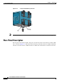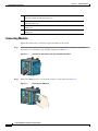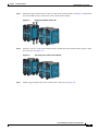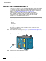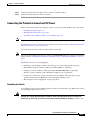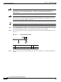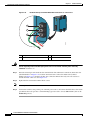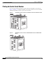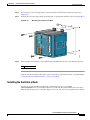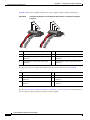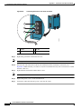
1
Cisco IE 3000 Switch Hardware
Installation Guide
June 2008
Americas Headquarters
Cisco Systems, Inc.
170 West Tasman Drive
San Jose, CA 95134-1706
USA
http://www.cisco.com
Tel: 408 526-4000
800 553-NETS (6387)
Fax: 408 527-0883
Text Part Number: OL-13017-01
THE SPECIFICATIONS AND INFORMATION REGARDING THE PRODUCTS IN THIS MANUAL ARE SUBJECT TO CHANGE WITHOUT NOTICE. ALL
STATEMENTS, INFORMATION, AND RECOMMENDATIONS IN THIS MANUAL ARE BELIEVED TO BE ACCURATE BUT ARE PRESENTED WITHOUT
WARRANTY OF ANY KIND, EXPRESS OR IMPLIED. USERS MUST TAKE FULL RESPONSIBILITY FOR THEIR APPLICATION OF ANY PRODUCTS.
THE SOFTWARE LICENSE AND LIMITED WARRANTY FOR THE ACCOMPANYING PRODUCT ARE SET FORTH IN THE INFORMATION PACKET THAT
SHIPPED WITH THE PRODUCT AND ARE INCORPORATED HEREIN BY THIS REFERENCE. IF YOU ARE UNABLE TO LOCATE THE SOFTWARE LICENSE
OR LIMITED WARRANTY, CONTACT YOUR CISCO REPRESENTATIVE FOR A COPY.
The following information is for FCC compliance of Class A devices: This equipment has been tested and found to comply with the limits for a Class A digital device, pursuant
to part 15 of the FCC rules. These limits are designed to provide reasonable protection against harmful interference when the equipment is operated in a commercial
environment. This equipment generates, uses, and can radiate radio-frequency energy and, if not installed and used in accordance with the instruction manual, may cause
harmful interference to radio communications. Operation of this equipment in a residential area is likely to cause harmful interference, in which case users will be required
to correct the interference at their own expense.
The following information is for FCC compliance of Class B devices: The equipment described in this manual generates and may radiate radio-frequency energy. If it is not
installed in accordance with Cisco’s installation instructions, it may cause interference with radio and television reception. This equipment has been tested and found to
comply with the limits for a Class B digital device in accordance with the specifications in part 15 of the FCC rules. These specifications are designed to provide reasonable
protection against such interference in a residential installation. However, there is no guarantee that interference will not occur in a particular installation.
Modifying the equipment without Cisco’s written authorization may result in the equipment no longer complying with FCC requirements for Class A or Class B digital
devices. In that event, your right to use the equipment may be limited by FCC regulations, and you may be required to correct any interference to radio or television
communications at your own expense.
You can determine whether your equipment is causing interference by turning it off. If the interference stops, it was probably caused by the Cisco equipment or one of its
peripheral devices. If the equipment causes interference to radio or television reception, try to correct the interference by using one or more of the following measures:
• Turn the television or radio antenna until the interference stops.
• Move the equipment to one side or the other of the television or radio.
• Move the equipment farther away from the television or radio.
• Plug the equipment into an outlet that is on a different circuit from the television or radio. (That is, make certain the equipment and the television or radio are on circuits
controlled by different circuit breakers or fuses.)
Modifications to this product not authorized by Cisco Systems, Inc. could void the FCC approval and negate your authority to operate the product.
The Cisco implementation of TCP header compression is an adaptation of a program developed by the University of California, Berkeley (UCB) as part of UCB’s public
domain version of the UNIX operating system. All rights reserved. Copyright © 1981, Regents of the University of California.
NOTWITHSTANDING ANY OTHER WARRANTY HEREIN, ALL DOCUMENT FILES AND SOFTWARE OF THESE SUPPLIERS ARE PROVIDED “AS IS” WITH
ALL FAULTS. CISCO AND THE ABOVE-NAMED SUPPLIERS DISCLAIM ALL WARRANTIES, EXPRESSED OR IMPLIED, INCLUDING, WITHOUT
LIMITATION, THOSE OF MERCHANTABILITY, FITNESS FOR A PARTICULAR PURPOSE AND NONINFRINGEMENT OR ARISING FROM A COURSE OF
DEALING, USAGE, OR TRADE PRACTICE.
IN NO EVENT SHALL CISCO OR ITS SUPPLIERS BE LIABLE FOR ANY INDIRECT, SPECIAL, CONSEQUENTIAL, OR INCIDENTAL DAMAGES, INCLUDING,
WITHOUT LIMITATION, LOST PROFITS OR LOSS OR DAMAGE TO DATA ARISING OUT OF THE USE OR INABILITY TO USE THIS MANUAL, EVEN IF CISCO
OR ITS SUPPLIERS HAVE BEEN ADVISED OF THE POSSIBILITY OF SUCH DAMAGES.
CCDE, CCENT, Cisco Eos, Cisco Lumin, Cisco StadiumVision, the Cisco logo, DCE, and Welcome to the Human Network are trademarks; Changing the Way We Work,
Live, Play, and Learn is a service mark; and Access Registrar, Aironet, AsyncOS, Bringing the Meeting To You, Catalyst, CCDA, CCDP, CCIE, CCIP, CCNA, CCNP, CCSP,
CCVP, Cisco, the Cisco Certified Internetwork Expert logo, Cisco IOS, Cisco Press, Cisco Systems, Cisco Systems Capital, the Cisco Systems logo, Cisco Unity,
Collaboration Without Limitation, EtherFast, EtherSwitch, Event Center, Fast Step, Follow Me Browsing, FormShare, GigaDrive, HomeLink, Internet Quotient, IOS, iPhone,
iQ Expertise, the iQ logo, iQ Net Readiness Scorecard, iQuick Study, IronPort, the IronPort logo, LightStream, Linksys, MediaTone, MeetingPlace, MGX, Networkers,
Networking Academy, Network Registrar, PCNow, PIX, PowerPanels, ProConnect, ScriptShare, SenderBase, SMARTnet, Spectrum Expert, StackWise, The Fastest Way to
Increase Your Internet Quotient, TransPath, WebEx, and the WebEx logo are registered trademarks of Cisco Systems, Inc. and/or its affiliates in the United States and certain
other countries.
All other trademarks mentioned in this document or Website are the property of their respective owners. The use of the word partner does not imply a partnership relationship
between Cisco and any other company. (0804R)
Any Internet Protocol (IP) addresses used in this document are not intended to be actual addresses. Any examples, command display output, and figures included in the
document are shown for illustrative purposes only. Any use of actual IP addresses in illustrative content is unintentional and coincidental.
Cisco IE 3000 Switch Hardware Installation Guide
© 2008 Cisco Systems, Inc. All rights reserved.
C O N T E N T S
Preface
ix
Audience
Purpose
ix
ix
Conventions
ix
Related Publications
x
Obtaining Documentation, Obtaining Support, and Security Guidelines
CHAPTER
1
Overview
x
1-1
Overview
1-1
Switch Models
1-2
Front-Panel Description 1-2
10/100 Ports 1-5
Dual-Purpose Ports 1-5
100BASE-FX Ports 1-5
Power and Relay Connector 1-5
Console Port 1-6
LEDs 1-6
Setup LED 1-8
System LED 1-9
Alarm LED 1-9
Power Status LED 1-9
10/100 Port Status LEDs 1-10
100Base-FX Port Status LEDs 1-10
Dual-Purpose Port LEDs 1-11
Compact Flash Memory Card
Rear-Panel Description
1-12
Power Converter (Optional)
Management Options
2
Switch Installation
1-13
1-14
Network Configurations
CHAPTER
1-11
1-15
2-1
Preparing for Installation
Warnings 2-2
2-1
Cisco IE 3000 Switch Hardware Installation Guide
OL-13017-01
iii
Contents
Installation Guidelines 2-3
Environment and Enclosure Guidelines:
Other Guidelines 2-3
Verifying Package Contents 2-5
Adding Modules to the Switch 2-5
Expansion Module Configurations
Connecting Modules 2-8
2-3
2-5
Installing or Removing the Compact Flash Memory Card
2-10
Verifying Switch Operation 2-11
Connecting a PC or a Terminal to the Console Port 2-12
Connecting the Protective Ground and DC Power 2-13
Grounding the Switch 2-13
Wiring the DC Power Source 2-16
Attach the Power and Relay Connector to the Switch
Running POST 2-22
Power On the Switch 2-22
Verify POST Results 2-22
Disconnect Power 2-22
Installing the Switch 2-23
Installing the Switch on a DIN Rail 2-23
Installing the Switch on the Wall 2-27
Installing the Switch in a Rack 2-29
Removing the Switch from a DIN Rail or a Rack
Connecting Power and Alarm Circuits 2-32
Wiring the Protective Ground and DC Power
Wiring the External Alarms 2-33
2-21
2-31
2-32
Connecting Destination Ports 2-36
Connecting to 10/100 and 10/100/1000 Ports 2-36
Installing and Removing SFP Modules 2-37
Installing SFP Modules into SFP Module Slots 2-38
Removing SFP Modules from SFP Module Slots 2-40
Connecting to SFP Modules 2-41
Connecting to a Dual-Purpose Port 2-42
Connecting to 100BASE-FX Ports 2-43
Connecting the Switch to the Power Converter 2-44
Attaching the Power Converter to the Switch 2-45
Installing the Power Converter on a DIN Rail, Wall, or Rack Adapter
Connecting the DC Power Clip 2-46
Connecting the Power Converter to an AC Power Source 2-47
2-46
Cisco IE 3000 Switch Hardware Installation Guide
iv
OL-13017-01
Contents
Preparing the AC Power Cord 2-47
Connecting the AC Power Cord to the Power Converter 2-48
Connecting the Power Converter to a DC Power Source 2-51
Applying Power to the Power Converter 2-53
Where to Go Next
CHAPTER
3
Troubleshooting
2-53
3-1
Diagnosing Problems 3-1
Verify Switch POST Results 3-1
Verify Switch LEDs 3-2
Verify Switch Connections 3-2
Bad or Damaged Cable 3-2
Ethernet and Fiber Cables 3-2
Link Status 3-3
Transceiver Issues 3-3
Port and Interface Settings 3-3
Ping End Device 3-3
Spanning Tree Loops 3-4
Verify Switch Performance 3-4
Speed, Duplex, and Autonegotiation
Autonegotiation and NIC 3-4
Cabling Distance 3-5
3-4
How to Clear the Switch IP Address and Configuration
How to Recover Passwords
3-5
Finding the Switch Serial Number
3-6
APPENDIX
A
Technical Specifications
APPENDIX
B
Installation In a Hazardous Environment
Preparing for Installation
Warnings B-2
3-5
A-1
B-1
B-1
North American Hazardous Location Approval B-5
EMC Environmental Conditions for Products Installed in the European Union
Installation Guidelines B-5
Environment and Enclosure Guidelines: B-5
Other Guidelines B-6
Verifying Package Contents B-7
Adding Modules to the Switch
B-5
B-8
Cisco IE 3000 Switch Hardware Installation Guide
OL-13017-01
v
Contents
Expansion Module Configurations
Connecting Modules B-11
B-9
Installing or Removing the Compact Flash Memory Card
B-13
Verifying Switch Operation B-14
Connecting a PC or a Terminal to the Console Port B-15
Connecting the Protective Ground and DC Power B-16
Grounding the Switch B-17
Wiring the DC Power Source B-19
Attach the Power and Relay Connector to the Switch
Running POST B-25
Power On the Switch B-25
Verify POST Results B-25
Disconnect Power B-25
Installing the Switch B-26
Installing the Switch on a DIN Rail B-27
Installing the Switch on a Wall B-31
Installing the Switch in a Rack B-33
Removing the Switch from a DIN Rail or a Rack
B-24
B-35
Connecting Power and Alarm Circuits B-36
Information about the Sealed Relay Device B-37
Wiring the Protective Ground and DC Power B-37
Wiring the External Alarms B-38
Connecting Destination Ports B-41
Connecting to 10/100 and 10/100/1000 Ports B-41
Installing and Removing SFP Modules B-42
Installing SFP Modules into SFP Module Slots B-43
Removing SFP Modules from SFP Module Slots B-44
Connecting to SFP Modules B-45
Connecting to a Dual-Purpose Port B-46
Connecting to 100BASE-FX Ports B-48
Connecting the Switch to the Power Converter B-49
Attaching the Power Converter to the Switch B-49
Installing the Power Converter on a DIN Rail, Wall, or Rack Adapter
Connecting the DC Power Clip B-52
Connecting the Power Converter to an AC Power Source B-53
Preparing the AC Power Cord B-53
Connecting the AC Power Cord to the Power Converter B-54
Connecting the Power Converter to a DC Power Source B-57
Applying Power to the Power Converter B-59
B-52
Cisco IE 3000 Switch Hardware Installation Guide
vi
OL-13017-01
Contents
Where to Go Next
APPENDIX
C
Cable and Connectors
B-59
C-1
Connector Specifications C-1
10/100 Ports C-1
Connecting to 10BASE-T- and 100BASE-TX-Compatible Devices
Connecting to 1000BASE-T Devices C-1
100BASE-FX Ports C-3
SFP Module Ports C-3
Dual-Purpose Ports C-4
Console Port C-4
Cable and Adapter Specifications C-4
SFP Module Cable Specifications C-4
Two Twisted-Pair Cable Pinouts C-5
Four Twisted-Pair Cable Pinouts for 1000BASE-T Ports
Crossover Cable and Adapter Pinouts C-7
Identifying a Crossover Cable C-7
Four Twisted-Pair Cable Pinouts for 1000BASE-T Ports
Adapter Pinouts C-8
APPENDIX
D
Configuring the Switch with the CLI-Based Setup Program
Accessing the CLI from the Console Port
C-1
C-6
C-7
D-1
D-1
Entering the Initial Configuration Information
IP Settings D-2
Completing the Setup Program D-2
D-2
INDEX
Cisco IE 3000 Switch Hardware Installation Guide
OL-13017-01
vii
Contents
Cisco IE 3000 Switch Hardware Installation Guide
viii
OL-13017-01
Preface
Audience
This guide is for the networking or computer technician responsible for installing Cisco IE 3000 series
switches. We assume that you are familiar with the concepts and terminology of Ethernet and local area
networking.
Purpose
This guide documents the hardware features of the Cisco IE 3000 switches. It describes the physical and
performance characteristics of each switch, explains how to install a switch, and provides
troubleshooting information.
This guide does not describe system messages that you might receive or how to configure your switch.
For more information, see the switch getting started guide, the switch software configuration guide, the
switch command reference, and the switch system message guide on the Cisco.comTechnical Support
and Documentation home page. For information about the standard Cisco IOS Release 12.1 or 12.2
commands, see the Cisco IOS documentation set from the Cisco.com home page at
Technical Support and Documentation > Documentation. On the Cisco Documentation home page,
select Release 12.1 or 12.2 from the Cisco IOS Software drop-down list.
Conventions
This document uses the following conventions and symbols for notes, cautions, and warnings.
Note
Caution
Means reader take note. Notes contain helpful suggestions or references to materials not contained in
this manual.
Means reader be careful. In this situation, you might do something that could result in equipment
damage or loss of data.
Cisco IE 3000 Switch Hardware Installation Guide
OL-13017-01
ix
Preface
Warning
This warning symbol means danger. You are in a situation that could cause bodily injury. Before you
work on any equipment, be aware of the hazards involved with electrical circuitry and be familiar
with standard practices for preventing accidents. Use the statement number provided at the end of
each warning to locate its translation in the translated safety warnings that accompanied this device.
Statement 1071
The safety warnings for this product are translated into several languages in the Regulatory Compliance
and Safety Information for the Cisco IE 3000 Switch that ships with the product. The EMC regulatory
statements are also included in that guide.
Related Publications
Before installing, configuring, or upgrading the switch, see the release notes on Cisco.com for the latest
information.
These documents provide complete information about the switch and are available on Cisco.com:
•
Cisco IE 3000 Switch Getting Started Guide
•
Regulatory Compliance and Safety Information for the Cisco IE 3000 Switch
•
Release Notes for the Cisco IE 3000 Switch
•
Cisco IE 3000 Switch Software Configuration Guide
•
Cisco IE 3000 Switch Command Reference
•
Cisco IE 3000 Switch System Message Guide
•
Device manager online help (available on the switch)
•
Cisco Small Form-Factor Pluggable Modules Installation Notes
These compatibility matrix documents are available from this Cisco.com site:
http://www.cisco.com/en/US/products/hw/modules/ps5455/products_device_support_tables_list.html
•
Cisco Gigabit Ethernet Transceiver Modules Compatibility Matrix (not orderable but available on
Cisco.com)
•
Cisco Small Form-Factor Pluggable Modules Compatibility Matrix (not orderable but available on
Cisco.com)
Obtaining Documentation, Obtaining Support, and Security
Guidelines
For information on obtaining documentation, obtaining support, providing documentation feedback,
security guidelines, and also recommended aliases and general Cisco documents, see the monthly
What’s New in Cisco Product Documentation, which also lists all new and revised Cisco technical
documentation, at:
http://www.cisco.com/en/US/docs/general/whatsnew/whatsnew.html
Cisco IE 3000 Switch Hardware Installation Guide
x
OL-13017-01
CH A P T E R
1
Overview
This chapter provides these topics that describe the Cisco Industrial Ethernet (IE) 3000 switch, hereafter
referred to as the switch.
This chapter provides a functional overview of the switches and covers these topics:
•
Overview, page 1-1
•
Switch Models, page 1-2
•
Front-Panel Description, page 1-2
•
Compact Flash Memory Card, page 1-11
•
Rear-Panel Description, page 1-12
•
Power Converter (Optional), page 1-13
•
Management Options, page 1-14
•
Network Configurations, page 1-15
Overview
The Cisco IE 3000 switch provides a rugged and secure switching infrastructure for harsh environments.
It is suitable for industrial Ethernet applications, including factory automation, intelligent transportation
systems (ITSs), substations, and other deployments in harsh environments.
You can connect these switches to office networking devices like Cisco IP Phones, Cisco Wireless
Access Points workstations, and other devices such as servers, routers, and other switches. In industrial
environments, you can connect any Ethernet-enabled industrial communication devices, including
programmable logic controllers (PLCs), human-machine interfaces (HMIs), drives, sensors, traffic
signal controllers, and intelligent electronic devices (IEDs).
You can mount the switch on a DIN rail in an industrial enclosure, on a wall or panel, and with some
restrictions, in a standard 19-inch rack. Its components are designed to withstand extremes in
temperature, vibration, and shock that are common in an industrial environment.
Note
The switch does not have cooling fans.
Cisco IE 3000 Switch Hardware Installation Guide
OL-13017-01
1-1
Chapter 1
Overview
Switch Models
Switch Models
Table 1-1 describes the switch and the expansion modules. The Cisco IE-3000-4TC and
the Cisco IE-3000-8TC are the switch models, and the Cisco IEM-3000-8TM and the
Cisco IEM-3000-8FM are expansion modules that you can connect to increase the number of ports. For
instructions on how to connect the expansion modules to the switch, see the “Adding Modules to the
Switch” section on page 2-5.
.
Table 1-1
Cisco IE 3000 Switch Models
Switch Model
Description
Cisco IE-3000-4TC
4 10/100BASE-T Ethernet ports and 2 dual-purpose ports, each with a
10/100/1000BASE-T copper port and an SFP (small form-factor pluggable)
module slot
Cisco IE-3000-8TC
8 10/100BASE-T Ethernet ports and 2 dual-purpose ports
Cisco IEM-3000-8TM
Expansion module with 8 10/100BASE-T copper Ethernet ports
Cisco IEM-3000-8FM
Expansion module with 8 100BASE-FX fiber-optic Ethernet ports
Front-Panel Description
This section describes the front panel and includes these sections:
•
10/100 Ports, page 1-5
•
Dual-Purpose Ports, page 1-5
•
100BASE-FX Ports, page 1-5
•
Power and Relay Connector, page 1-5
•
Console Port, page 1-6
•
LEDs, page 1-6
The switch front panel contains the ports, the LEDs, and the power and relay connectors. Figure 1-1 to
Figure 1-4 show the switch and expansion module front panels.
Cisco IE 3000 Switch Hardware Installation Guide
1-2
OL-13017-01
Chapter 1
Overview
Front-Panel Description
Figure 1-1
Cisco IE-3000-8TC Switch
1
201699
2
3
4
5
1
Power and relay connectors
4
10/100 ports
2
Console port
5
Protective ground connection
3
Dual-purpose ports
Figure 1-2
Cisco IE-3000-4TC Switch
1
201700
2
3
4
5
1
Power and relay connectors
4
10/100 ports
2
Console port
5
Protective ground connection
3
Dual-purpose ports
Cisco IE 3000 Switch Hardware Installation Guide
OL-13017-01
1-3
Chapter 1
Overview
Front-Panel Description
Cisco IEM-3000-8TM Module
201702
Figure 1-3
1
1
10/100 ports
Cisco IEM-3000-8FM Module
201701
Figure 1-4
1
1
100BASE-FX ports
Cisco IE 3000 Switch Hardware Installation Guide
1-4
OL-13017-01
Chapter 1
Overview
Front-Panel Description
10/100 Ports
You can set the 10/100 ports to operate at 10 or 100 Mb/s in full-duplex or half-duplex mode. You can
also set these ports for speed and duplex autonegotiation in compliance with IEEE 802.3AB. (The
default setting is autonegotiate.) When set for autonegotiation, the port senses the speed and duplex
settings of the attached device and advertises its own capabilities. If the connected device also supports
autonegotiation, the switch port negotiates the best connection (that is, the fastest line speed that both
devices support and full-duplex transmission if the attached device supports it) and configures itself
accordingly. In all cases, the attached device must be within 328 feet (100 meters). 100BASE-TX traffic
requires Category 5 cable. 10BASE-T traffic can use Category 3 or Category 4 cables.
When connecting the switch to workstations, servers, routers, and Cisco IP Phones, be sure that the cable
is a straight-through cable.
You can use the mdix auto interface configuration command in the command-line interface (CLI) to
enable the automatic medium-dependent interface crossover (auto-MDIX) feature. When the
auto-MDIX feature is enabled, the switch detects the required cable type for copper Ethernet connections
and configures the interfaces accordingly. For configuration information for this feature, see the switch
software configuration guide or the switch command reference.
Dual-Purpose Ports
A dual-purpose port can be configured as either a 10/100/1000 port or as an SFP module port. Only one
port can be active at a time. If both ports are connected, the SFP module port has priority.
You can set the 10/100/1000 ports to operate at 10, 100, or 1000 Mb/s in full-duplex or half-duplex
mode. You can configure them as fixed 10, 100, or 1000 Mb/s (Gigabit) Ethernet ports and can configure
the duplex setting. (See the switch software configuration for more information.)
You can use Gigabit Ethernet SFP modules to establish fiber-optic connections to other switches. These
transceiver modules are field-replaceable, providing the uplink interfaces when inserted in an SFP
module slot. You use fiber-optic cables with LC connectors to connect to a fiber-optic SFP module.
For more information about these SFP modules, see your SFP module documentation or the release note
for your switch software.
100BASE-FX Ports
The IEEE 802.3u 100BASE-FX ports provide full-duplex 100 Mb/s connectivity over multimode fiber
(MMF) cables. These ports use a small-form-factor fixed (SFF) fiber-optic transceiver module that
accepts a dual LC connector. The cable can be up to 1.24 miles (2 km) in length.
Power and Relay Connector
You connect the DC power and alarm signals to the switch through two front panel connectors. One
connector provides primary DC power (supply A) and the major alarm signal, and a second connector
(supply B) provides secondary power and the minor alarm signal. The two connectors are physically
identical and are in the upper left side of the front panel. See Figure 1-2.
Cisco IE 3000 Switch Hardware Installation Guide
OL-13017-01
1-5
Chapter 1
Overview
Front-Panel Description
The switch accessory pack includes the mating power and relay connectors. These connectors provide
screw terminals for terminating the DC power and alarm wire and the connector plugs into the power
and relay receptacles on the front panel. The positive DC power connection is labeled V, and the return
connection is labeled RT (see Figure 1-5).
Figure 1-5
Power and Relay Connector
201815
V RT
A A
The switch can operate with a single power source or with dual power sources. When both power sources
are operational, the switch draws power from the DC source with the higher voltage. If one of the two
power sources fail, the other continues to power the switch.
The power and relay connectors also provide an interface for two independent alarm relays: the major
and the minor alarms. The relays can be activated for environmental, power supply, and port status alarm
conditions and can be configured to indicate an alarm with either open or closed contacts. The relay itself
is normally open, so under power failure conditions, the contacts are open. From the CLI, you can
associate any alarm condition with one or with both alarm relays.
Alarm relays often control an external alarm device, such as a bell or a light. To connect an external
alarm device to the relay, you must connect two relay contact wires to complete an electrical circuit. Both
alarm terminals on the power and relay connector are labeled A, and you can connect them without
regard to polarity.
See the switch software configuration guide for instructions on configuring the alarm relays.
For more information about the power and relay connector, see Appendix C, “Cable and Connectors.”
You can get replacement power and relay connectors (PWR-IE3000-CNCT=) by calling Cisco Technical
Support.
Console Port
You can connect a switch to a PC through the console port and the supplied RJ-45-to-DB-9 adapter cable.
If you want to connect a switch to a terminal, you need to provide an RJ-45-to-DB-25 female DTE
adapter. You can order a kit (part number ACS-DSBUASYN=) with that adapter from Cisco Systems.
For console-port and adapter-pinout information, see the “Two Twisted-Pair Cable Pinouts” section on
page C-5.
LEDs
You can use the LEDs to monitor the switch status, activity, and performance. Figure 1-6 to Figure 1-9
show the front panel LEDs, and the following sections describe them.
All LEDs are visible through the GUI management applications—the Cisco Network Assistant
application for multiple switches and the device manager GUI for a single switch. The switch software
configuration guide describes how to use the CLI to configure and to monitor individual switches and
switch clusters.
Cisco IE 3000 Switch Hardware Installation Guide
1-6
OL-13017-01
Chapter 1
Overview
Front-Panel Description
Figure 1-6
LEDs on the Cisco IE 3000 Switch
1
2
3
6
5
7
201703
4
8
1
Express setup button
5
Dual-purpose uplink port LED
2
System LED
6
Pwr B LED
3
Alarm LED
7
Pwr A LED
4
Setup LED
8
Port LED
LEDs on the Cisco IEM-3000-8TM Module
201706
Figure 1-7
1
1
10/100 port LED
Cisco IE 3000 Switch Hardware Installation Guide
OL-13017-01
1-7
Chapter 1
Overview
Front-Panel Description
LEDs on the Cisco IEM-3000-8FM Module
201705
Figure 1-8
1
1
100BASE -FX port LEDs
Setup LED
The Setup LED displays the express setup mode for the initial configuration. Table 1-2 lists the LED
colors and their meanings.
Table 1-2
Setup LED
Color
Setup Status
Off (dark)
Switch is configured as a managed switch.
Solid green
Switch is in initial setup.
Blinking green
Switch is in initial setup, in recovery, or initial setup is
incomplete.
Solid red
Switch failed to start initial setup or recovery because
there is no available switch port to which to connect the
management station. Disconnect a device from a switch
port, and then press the Express Setup button.
Cisco IE 3000 Switch Hardware Installation Guide
1-8
OL-13017-01
Chapter 1
Overview
Front-Panel Description
System LED
The System LED shows whether the system is receiving power and is functioning properly.
Table 1-3 lists the system LED colors and their meanings.
Table 1-3
System LED
Color
System Status
Off
System is not powered on.
Green
System is operating normally.
Red
Switch is not functioning properly.
Alarm LED
Table 1-4 lists the alarm LED colors and their meanings.
Table 1-4
Alarm Status LED
Color
System Status
Off
Alarms are not configured, or the switch is off.
Green
Alarms are configured.
Blinking red
Switch has detected a major alarm.
Red
Switch has detected a minor alarm.
Power Status LED
The switch can operate with one or two DC power sources. Each DC input has an associated LED that
shows the status of the corresponding DC input. If power is present on the circuit, the LED is green. If
power is not present, the LED color depends on the alarm configuration. If alarms are configured, the
LED is red when power is not present; otherwise, the LED is off.
If the switch has dual power sources, the switch draws power from the power source with the higher
voltage. If the one of the DC sources fails, the alternate DC source powers the switch, and the
corresponding power status LED is green. The power status for the failed DC source is either off or red,
depending on the alarm configuration.
Table 1-5 lists the power status LED colors and meanings.
Table 1-5
Power Status LEDs
Color
System Status
Off
Power is not present on the circuit, or the system is not powered up.
Green
Power is present on the associated circuit.
Red
Power is not present on the associated circuit, and the power supply alarm is
configured.
Cisco IE 3000 Switch Hardware Installation Guide
OL-13017-01
1-9
Chapter 1
Overview
Front-Panel Description
Note
The Pwr A and Pwr B LEDs show that power is not present on the switch if the power input drops below
the low valid level. The power status LEDs only show that power is present if the voltage at the switch
input exceeds the valid level. The difference, or hysteresis, ensures that the power status LEDs do not
oscillate at values near 18 V.
For information about the power LED colors during the power-on self-test (POST), see the “Verifying
Switch Operation” section on page 2-11.
10/100 Port Status LEDs
Each 10/100 port has a port status LED, also called a port LED, as shown in Figure 1-6, Figure 1-7, and
Figure 1-8. Table 1-6 displays LED information about the switch and the individual ports.
Table 1-6
10/100 Port Status LEDs
Color
System Status
Off
No link.
Solid green
Link present.
Blinking green Activity. Port is sending or receiving data.
Blinking
amber
A link blocked by Spanning Tree Protocol (STP) is
sending or receiving data.
Alternating
green-amber
Link fault. Error frames can affect connectivity, and errors
such as excessive collisions, CRC errors, and alignment and
jabber errors are monitored for a link-fault indication.
Solid amber
Port is not forwarding. Port was disabled by management, an
address violation, or STP.
Note
After a port is reconfigured, the port LED can remain
amber for up to 30 seconds while STP checks the
switch for possible loops.
100Base-FX Port Status LEDs
These LEDs display information about the individual ports. See Table 1-7.
Table 1-7
100BASE-FX MM Uplink Port Status LEDs
Color
System Status
Off
No link.
Solid green
Link is present.
Blinking green
Activity. Port is sending or receiving data.
Blinking amber
A link blocked by Spanning Tree Protocol (STP) is sending or receiving
data.
Alternating green-amber
Link is faulty.
Solid amber
Link is disabled.
Cisco IE 3000 Switch Hardware Installation Guide
1-10
OL-13017-01
Chapter 1
Overview
Compact Flash Memory Card
Dual-Purpose Port LEDs
Figure 1-9 shows the LEDs on a dual-purpose port. You can configure each port as either a 10/100/1000
port through the RJ-45 connector or as an SFP module, but not both at the same time. The LEDs show
how the port is being used (Ethernet or SFP module).
The LED colors have the same meanings as described in Table 1-6.
1
Dual-Purpose Port LEDs
2
3
4
1
203660
Figure 1-9
1
RJ-45 connector
3
2
RJ-45 port in-use LED 4
SFP module port in-use LED
SFP module slot
Compact Flash Memory Card
The switch supports a compact flash memory card that makes it possible to replace a failed switch
without reconfiguring the new switch. The slot for the compact flash memory card is on the bottom of
the switch. See Figure 1-10.
Note
For more information on inserting and removing the compact flash memory card, see the “Installing or
Removing the Compact Flash Memory Card” section on page 2-10.
Cisco IE 3000 Switch Hardware Installation Guide
OL-13017-01
1-11
Chapter 1
Overview
Rear-Panel Description
Compact Flash Memory Card Slot
201832
Figure 1-10
1
Note
Bottom
of switch
You can obtain replacement flash memory cards (CF-IE3000=) by calling Cisco Technical Support.
Rear-Panel Description
The rear panel of the switch, modules, and power converter have latches for installation on either a DIN
rail or a wall. See Figure 1-11. The latches slide outward to position the switch over a DIN rail and slide
inward to secure the switch to a DIN rail. The feet stabilize the switch when it is mounted on the wall.
Cisco IE 3000 Switch Hardware Installation Guide
1-12
OL-13017-01
Chapter 1
Overview
Power Converter (Optional)
Figure 1-11
1
201697
2
Cisco IE 3000 Switch Rear Panel
1
DIN rail latch
2
Foot in recessed position
Power Converter (Optional)
The switch can be used with an optional AC/DC power converter. The power converter
(PWR-IE3000-AC) can supply 24-VDC power to one switch and up to two modules. The power
converter is mounted on the side of a switch and provides power to the switch through a preassembled
power cable.
Note
The power converter (PWR-IE3000-AC=) is sold separately.
You can get a replacement power cable (PWR-IE3000-CLP=) by calling Cisco Technical Support.
For installation and connection procedures for the power converter, see the “Connecting the Switch to
the Power Converter” section on page 2-44.
Cisco IE 3000 Switch Hardware Installation Guide
OL-13017-01
1-13
Chapter 1
Overview
Management Options
Figure 1-12 displays the power converter.
Figure 1-12
Cisco IE 3000 Switch AC/DC Power Converter
1
2
202314
3
1
DC output connector
2
Status LED
3
AC/DC input power connector
Management Options
The switch supports these management options:
•
Cisco Network Assistant
Cisco Network Assistant is a PC-based network management GUI application optimized for LANs
of small and medium-sized businesses. Through a GUI, users can configure and manage switch
clusters or standalone switches. Cisco Network Assistant is available at no cost and can be
downloaded from this URL:
http://www.cisco.com/go/networkassistant
For information on starting the Cisco Network Assistant application, see the Getting Started with
Cisco Network Assistant guide on Cisco.com.
•
Device Manager
You can use the device manager, which is in the switch memory, to manage individual and
standalone switches. This web interface offers quick configuration and monitoring. You can access
the device manager from anywhere in your network through a web browser. For more information,
see the getting started guide and the device manager online help.
•
Cisco IOS CLI
The switch CLI is based on Cisco IOS software and is enhanced to support desktop-switching
features. You can fully configure and monitor the switch. You can access the CLI either by
connecting your management station directly to the switch management port, or a console port, or
by using Telnet from a remote management station. See the switch command reference on
Cisco.com for more information.
Cisco IE 3000 Switch Hardware Installation Guide
1-14
OL-13017-01
Chapter 1
Overview
Network Configurations
•
CiscoWorks application
The CiscoWorks device-management application displays the switch image that you can use to set
configuration parameters and to view the switch status and performance information. The
CiscoView application, which you purchase separately, can be a standalone application or part of a
Simple Network Management Protocol (SNMP) platform. See the CiscoView documentation for
more information.
•
SNMP network management
You can manage switches from a SNMP-compatible management station that is running platforms
such as HP OpenView or SunNet Manager. The switch supports a comprehensive set of Management
Information Base (MIB) extensions and four Remote Monitoring (RMON) groups. See the switch
software configuration guide on Cisco.com and the documentation that came with your SNMP
application for more information.
•
Common Industrial Protocol
The Common Industrial Protocol (CIP) management objects are supported. The Cisco IE 3000 can
be managed by CIP-based management tools, allowing the user to manage an entire industrial
automation system with one tool.
Network Configurations
See the switch software configuration guide on Cisco.com for network configuration concepts and
examples of using the switch to create dedicated network segments and interconnecting the segments
through Gigabit Ethernet connections.
Cisco IE 3000 Switch Hardware Installation Guide
OL-13017-01
1-15
Chapter 1
Overview
Network Configurations
Cisco IE 3000 Switch Hardware Installation Guide
1-16
OL-13017-01
CH A P T E R
2
Switch Installation
This chapter describes how to install your switch, interpret the power-on self-test (POST), and connect
the switch to other devices.
Caution
If your installation is in a hazardous environment, see Appendix B, “Installation In a Hazardous
Environment” for instructions.
Read these topics, and perform the procedures in this order:
•
Preparing for Installation, page 2-1
•
Adding Modules to the Switch, page 2-5
•
Installing or Removing the Compact Flash Memory Card, page 2-10
•
Verifying Switch Operation, page 2-11
•
Installing the Switch, page 2-23
•
Connecting Power and Alarm Circuits, page 2-32
•
Connecting Destination Ports, page 2-36
•
Connecting the Switch to the Power Converter, page 2-44
•
Where to Go Next, page 2-53
Preparing for Installation
This section provides information about these topics:
•
Warnings, page 2-2
•
Installation Guidelines, page 2-3
•
Verifying Package Contents, page 2-5
Cisco IE 3000 Switch Hardware Installation Guide
OL-13017-01
2-1
Chapter 2
Switch Installation
Preparing for Installation
Warnings
These warnings are translated into several languages in the Regulatory Compliance and Safety
Information Guide.
Warning
Before working on equipment that is connected to power lines, remove jewelry (including rings,
necklaces, and watches). Metal objects will heat up when connected to power and ground and can
cause serious burns or weld the metal object to the terminals. Statement 43
Warning
Do not work on the system or connect or disconnect cables during periods of lightning activity.
Statement 1001
Warning
Before performing any of the following procedures, ensure that power is removed from the DC circuit.
Statement 1003
Warning
Read the installation instructions before you connect the system to its power source. Statement 1004
Warning
This unit is intended for installation in restricted access areas. A restricted access area can be
accessed only through the use of a special tool, lock and key, or other means of security.
Statement 1017
Warning
This equipment must be grounded. Never defeat the ground conductor or operate the equipment in the
absence of a suitably installed ground conductor. Contact the appropriate electrical inspection
authority or an electrician if you are uncertain that suitable grounding is available. Statement 1024
Warning
This unit might have more than one power supply connection. All connections must be removed to
de-energize the unit. Statement 1028
Warning
Only trained and qualified personnel should be allowed to install, replace, or service this equipment.
Statement 1030
Warning
Ultimate disposal of this product should be handled according to all national laws and regulations.
Statement 1040
Warning
For connections outside the building where the equipment is installed, the following ports must be
connected through an approved network termination unit with integral circuit protection.
10/100/1000 Ethernet Statement 1044
Cisco IE 3000 Switch Hardware Installation Guide
2-2
OL-13017-01
Chapter 2
Switch Installation
Preparing for Installation
Warning
To prevent the system from overheating, do not operate it in an area that exceeds the maximum
recommended ambient temperature of:
140°F (60°C) Statement 1047
Warning
Installation of the equipment must comply with local and national electrical codes. Statement 1074
Warning
To prevent airflow restriction, allow clearance around the ventilation openings to be at least:
4.13 in. (105 mm). Statement 1076
Installation Guidelines
When determining where to place the switch, observe these guidelines.
Environment and Enclosure Guidelines:
Review these environmental and enclosure guidelines before installation:
•
This equipment is intended for use in a Pollution Degree 2 industrial environment, in overvoltage
Category II applications (as defined in IEC publication 60664-1), at altitudes up to 9842 ft (3 km)
without derating.
•
This equipment is considered Group 1, Class A industrial equipment, according to IEC/CISPR
Publication 11. Without appropriate precautions, there may be potential difficulties ensuring
electromagnetic compatibility in other environments due to conducted as well as radiated
disturbance.
•
This equipment is supplied as open-type equipment. It must be mounted within an enclosure that is
suitably designed for those specific environmental conditions that will be present and appropriately
designed to prevent personal injury resulting from accessibility to live parts. The enclosure must
have suitable flame-retardant properties to prevent or minimize the spread of flame, complying with
a flame-spread rating of 5VA, V2, V1, V0 (or equivalent) if nonmetallic. The interior of the
enclosure must be accessible only by the use of a tool. Subsequent sections of this publication might
contain additional information regarding specific enclosure-type ratings that are required to comply
with certain product safety certifications.
Other Guidelines
These are other installation guidelines:
Caution
Proper ESD protection is required whenever you handle Cisco equipment. Installation and
maintenance personnel should be properly grounded by using ground straps to eliminate the risk of
ESD damage to the switch.
Do not touch connectors or pins on component boards. Do not touch circuit components inside the
switch. When not in use, store the equipment in appropriate static-safe packaging.
Cisco IE 3000 Switch Hardware Installation Guide
OL-13017-01
2-3
Chapter 2
Switch Installation
Preparing for Installation
•
Personnel responsible for the application of safety-related programmable electronic systems (PES)
shall be aware of the safety requirements in the application of the system and shall be trained in
using the system.
•
This product is grounded through the DIN rail to chassis ground. Use zinc-plated yellow-chromate
steel DIN rail to assure proper grounding. The use of other DIN rail materials (such as aluminum,
plastic, and so on) that can corrode, oxidize, or are poor conductors can result in improper or
intermittent grounding. Secure the DIN rail to the mounting surface approximately every 7.8 in. (200
mm), and use end-anchors appropriately.
When determining where to place the switch, observe these guidelines:
•
Before installing the switch, first verify that the switch is operational by powering it on and running
POST. Follow the procedures in the “Verifying Switch Operation” section on page 2-11.
•
For 10/100 ports and 10/100/1000 ports, the cable length from a switch to an attached device cannot
exceed 328 feet (100 meters).
•
For 100BASE-FX fiber-optic ports, the cable length from a switch to an attached device cannot
exceed 6562 ft (2 km).
•
Operating environment is within the ranges listed in Appendix A, “Technical Specifications.”
•
Clearance to front and rear panels meets these conditions:
– Front-panel LEDs can be easily read.
– Access to ports is sufficient for unrestricted cabling.
– Front-panel direct current (DC) power and relay connector is within reach of the connection to
the DC power source.
•
Airflow around the switch and through the vents is unrestricted. To prevent the switch from
overheating, there must be the following minimum clearances:
– Top and bottom: 4.13 in. (105 mm)
– Exposed side (not connected to the module): 3.54 in. (90 mm)
– Front: 2.56 in. (65 mm)
•
Temperature surrounding the unit does not exceed 140°F (60°C).
Note
When the switch is installed in an industrial enclosure, the temperature within the enclosure
is greater than normal room temperature outside the enclosure.
The temperature inside the enclosure cannot exceed 140°F (60°C), the maximum ambient
enclosure temperature of the switch.
Caution
•
Cabling is away from sources of electrical noise, such as radios, power lines, and fluorescent
lighting fixtures.
•
Connect the unit only to a Class 2 DC power source.
This equipment is only suitable for use in Class I, Division 2, Groups A, B, C, D, or nonhazardous
locations.
Cisco IE 3000 Switch Hardware Installation Guide
2-4
OL-13017-01
Chapter 2
Switch Installation
Adding Modules to the Switch
Verifying Package Contents
Carefully remove the contents from the shipping container, and check each item for damage. If any item
is missing or damaged, contact your Cisco representative or reseller for support. Return all packing
materials to the shipping container and save them.
The switch is shipped with these items:
•
Documentation CD that includes:
– Cisco IE 3000 Switch Getting Started Guide (in English, German, French, Spanish, Italian,
Japanese, and simplified Chinese)
– Regulatory Compliance and Safety Information for the Cisco IE 3000 Switch
Note
•
Regulatory Compliance and Safety Information for the Cisco IE 3000 Switch (safety warnings
translated in German)
•
Two power and relay connectors
•
RJ-45 to DB-9 console port adapter cable
To connect the switch functional ground, you need a ring terminal lug (such as Thomas & Bett part
number RC10-14 or equivalent).
If you want to connect a terminal to the switch console port, you need to provide an RJ-45-to-DB-25
female DTE adapter. You can order a kit (part number ACS-DSBUASYN=) with that adapter from Cisco.
For multimode (MM) connections, you can connect a 100BASE-FX port to a port on a target device by
using an dual-LC connector.
You can order a kit containing four spare latches (DINCLP-IE3000=) from Cisco.
Adding Modules to the Switch
The Cisco IE-3000-4TC or the Cisco IE-3000-8TC switch can operate as standalone devices with four
or eight Fast Ethernet ports, respectively. To increase the number of Fast Ethernet ports by 8 or 16, you
can connect the Cisco IEM-3000-8TM and the Cisco IEM-3000-8FM expansion modules. Depending on
the mix of switches and expansion modules, you can have up to 24 Fast Ethernet ports.
Note
The expansion modules cannot operate as standalone devices.
Expansion Module Configurations
To increase the number of ports, add one or two expansion modules to the switch. If you are installing
only one module, it can be either a Cisco IEM-3000-8TM or a Cisco IEM-3000-8FM. If you are
installing two modules, the first must be a Cisco IEM-3000-8TM, and the second can be either a Cisco
IEM-3000-8TM or a Cisco IEM-3000-8FM. You cannot add two Cisco IEM-3000-8FM expansion
modules.
Cisco IE 3000 Switch Hardware Installation Guide
OL-13017-01
2-5
Chapter 2
Switch Installation
Adding Modules to the Switch
Table 2-1 lists the port combinations using switch and expansion modules.
Table 2-1
Switch and Expansion Module Examples
Port Type
10/100FE
Switch and Expansion Modules Combination
100FX
Cisco IE-3000-4TC
4
1 Cisco IE-3000-4TC
8
1 Cisco IE-3000-8TC
4
8
12
8
1 Cisco IE-3000-4TC and 1 Cisco IEM-3000-8TM
8
16
12
24
1 Cisco IE-3000-8TC and 1 Cisco IEM-3000-8FM
1 Cisco IE-3000-8TC and 1 Cisco IEM-3000-8TM
8
20
16
1 Cisco IE-3000-4TC and 1 Cisco IEM-3000-8FM
1 Cisco IE-3000-4TC and 1 Cisco IEM-3000-8TM and 1 Cisco IEM-3000-8FM
1 Cisco IE-3000-4TC and 2 Cisco IEM-3000-8TM
8
1 Cisco IE-3000-8TC and 1 Cisco IEM-3000-8TM and 1 Cisco IEM-3000-8FM
1 Cisco IE-3000-8TC and 2 Cisco IEM-3000-8TM
Figure 2-1 shows example combinations of the Cisco IE-3000-4TC switch and expansion modules. Even
though the example configurations in Figure 2-1 show a Cisco IE-3000-4TC switch, the same
combinations of expansion modules can be used with a Cisco IE-3000-8TC switch.
Cisco IE 3000 Switch Hardware Installation Guide
2-6
OL-13017-01
Chapter 2
Switch Installation
Adding Modules to the Switch
Figure 2-1
Sample Combinations of Expansion Modules
1
2
3
201827
4
Cisco IE 3000 Switch Hardware Installation Guide
OL-13017-01
2-7
Chapter 2
Switch Installation
Adding Modules to the Switch
1
Cisco IE-3000-4TC switch with Cisco IEM-3000-8TM and Cisco IEM-3000-8FM
expansion modules (12 FE and 8 FX ports)
2
Cisco IE-3000-4TC switch with one Cisco IEM-3000-8FM expansion module
(4 FE and 8 FX ports)
3
Cisco IE-3000-4TC switch with one Cisco IEM-3000-8TM expansion modules
(12 FE ports)
4
Cisco IE-3000-4TC switch with two Cisco IEM-3000-8TM expansion modules
(20 FE ports)
Connecting Modules
Follow these directions to connect the expansion modules to the switch:
Step 1
Remove the side panel by firmly grasping both sides of it in the middle and pulling it outward. If
necessary, use a screwdriver to pry open the side panel. See Figure 2-2.
Opening the Side Panel of the Cisco IE-3000-8TC Switch
201822
Figure 2-2
Step 2
Remove the EMI protective cover from the connector on the switch. See Figure 2-2.
Removing the EMI Cover
203759
Figure 2-3
Cisco IE 3000 Switch Hardware Installation Guide
2-8
OL-13017-01
Chapter 2
Switch Installation
Adding Modules to the Switch
Step 3
Push up the upper module latches (at the top of the switch and the module). See Figure 2-4. Push down
the lower module latches (at the bottom of the switch and the module).
Pushing the Module Latches Up
201824
Figure 2-4
Step 4
Align the connectors on the switch and the module, and slide the switch and the module together to make
the connection. See Figure 2-5.
Connecting the Switch and the Module
201825
Figure 2-5
Step 5
Push the upper module latches down and the lower latches up. See Figure 2-6.
Cisco IE 3000 Switch Hardware Installation Guide
OL-13017-01
2-9
Chapter 2
Switch Installation
Installing or Removing the Compact Flash Memory Card
Pushing the Module Latches In
201826
Figure 2-6
Step 6
(Optional) if the first module attached was an Cisco IEM-3000-8TM, you can connect another
Cisco IEM-3000-8TM or Cisco IEM-3000-8FM expansion module. Follow Step 1 to Step 5 to connect
the module.
Installing or Removing the Compact Flash Memory Card
The switches store Cisco IOS software images and switch configurations on a removable flash memory
card. You can replace the switch without reconfiguring it. The switch ships with the compact flash
memory card installed. Verify that the card is in place on the bottom of the switch.
Cisco IE 3000 Switch Hardware Installation Guide
2-10
OL-13017-01
Chapter 2
Switch Installation
Verifying Switch Operation
Follow these directions to remove or replace the compact flash memory card:
Step 1
Locate the compact flash memory card slot on the bottom of the switch. See Figure 2-7.
Removing the Compact Flash Memory Card from the Switch
201851
Figure 2-7
1
Step 2
Bottom
of switch
Install or remove the card, as desired:
•
To remove the card, grasp the card top, and pull it out. Place it in an antistatic bag to protect it from
static discharge.
•
To install a card, slide it into the slot, and press it firmly in place. The card is keyed so that you
cannot insert it the wrong way.
Verifying Switch Operation
Before installing the switch in its final location, power on the switch, and verify that the switch passes
the power-on self-test (POST).
These sections describe the steps required to connect a PC or terminal to the switch console port, to
power on the switch, and to observe POST results:
•
Connecting a PC or a Terminal to the Console Port, page 2-12
•
Verifying Switch Operation, page 2-11
Cisco IE 3000 Switch Hardware Installation Guide
OL-13017-01
2-11
Chapter 2
Switch Installation
Verifying Switch Operation
Connecting a PC or a Terminal to the Console Port
To connect a PC to the console port, use the supplied RJ-45-to-DB-9 adapter cable. To connect a terminal
to the console port, you need to provide an RJ-45-to-DB-25 female DTE adapter. You can order a kit
(part number ACS-DSBUASYN=) with that adapter from Cisco. For console-port and adapter-pinout
information, see the “Cable and Adapter Specifications” section on page C-4.
The PC or terminal must support VT100 terminal emulation. The terminal-emulation
software—frequently a PC application such as HyperTerminal or Procomm Plus—makes
communication between the switch and your PC or terminal possible during the POST.
Follow these steps to connect the PC or terminal to the switch:
Step 1
Make sure that your terminal-emulation software is configured to communicate with the switch using
hardware flow control.
Step 2
Configure the baud rate and data format of the PC or terminal to match these console-port default
characteristics:
•
9600 baud
•
Eight data bits
•
One stop bit
•
No parity
After you get access to the switch, you can change the port baud rate. See the switch software
configuration guide for instructions.
Step 3
Insert the adapter cable in the console port. See Figure 2-8. (See the “Cable and Adapter Specifications”
section on page C-4 for pinout descriptions.)
Connecting to the Console Port
201868
Figure 2-8
Step 4
Attach the appropriate adapter to the terminal, if needed.
Cisco IE 3000 Switch Hardware Installation Guide
2-12
OL-13017-01
Chapter 2
Switch Installation
Verifying Switch Operation
Step 5
Connect the other end of the adapter cable to the PC or terminal adapter.
Step 6
Start the terminal-emulation software on the PC.
Connecting the Protective Ground and DC Power
These sections describe the steps required to connect a protective ground and DC power to the switch:
Note
•
Grounding the Switch, page 2-13
•
Wiring the DC Power Source, page 2-16
•
Attach the Power and Relay Connector to the Switch, page 2-21
The Cisco IE 3000 switch can be used with an optional AC/DC power converter (PWR-IE3000-AC).
For instructions on how to connect the power converter to the switch, see the “Connecting the Switch to
the Power Converter” section on page 2-44.
Locate the power and relay connector in the switch accessory kit.
Note
You can get replacement power and relay connectors (PWR-IE3000-CNCT=) by calling Cisco Technical
Support. See the “Obtaining Documentation, Obtaining Support, and Security Guidelines” section on
page x.
Obtain these necessary tools and equipment:
•
Ratcheting torque flathead screwdriver that exerts up to 15 inch-pounds (in-lb) of pressure
•
Ring terminal lug (such as Thomas & Bett part number 10RCR or equivalent)
•
Crimping tool (such as Thomas & Bett part number WT2000, ERG-2001, or equivalent)
•
10-gauge copper ground wire (such as Belden part number 9912 or equivalent)
•
For DC power connections, use UL- and CSA-rated, style 1007 or 1569 twisted-pair copper
appliance wiring material (AWM) wire (such as Belden part number 9318).
•
Wire-stripping tools for stripping 10- and 18-gauge wires
Grounding the Switch
To ground the switch to earth ground by using the ground screw, follow these steps. Make sure to follow
any grounding requirements at your site.
Warning
This equipment must be grounded. Never defeat the ground conductor or operate the equipment in the
absence of a suitably installed ground conductor. Contact the appropriate electrical inspection
authority or an electrician if you are uncertain that suitable grounding is available. Statement 1024
Cisco IE 3000 Switch Hardware Installation Guide
OL-13017-01
2-13
Chapter 2
Switch Installation
Verifying Switch Operation
Warning
Caution
Note
This equipment is intended to be grounded to comply with emission and immunity requirements.
Ensure that the switch functional ground lug is connected to earth ground during normal use.
Statement 1064
To make sure that the equipment is reliably connected to earth ground, follow the grounding procedure
instructions, and use a UL-listed ring terminal lug suitable for number 10-to-12 AWG wire, such as
Thomas & Bett part number 10RCR or equivalent.
Use at least a 4mm2 conductor to connect to the external grounding screw.
Step 1
Use a standard Phillips screwdriver or a ratcheting torque screwdriver with a Phillips head to remove the
ground screw from the front panel of the switch. Store the ground screw for later use.
Step 2
Use a wire-stripping tool to strip the 10-gauge wire to 0.5 inch. (12.7 mm) ± 0.02 inch (0.5 mm). See
Figure 2-9.
Figure 2-9
Stripping the Ground Wire
2
Step 3
3
104908
1
1
0.5 in. (12.7 mm) ± 0.02 in. (0.5 mm) 3
2
Insulation
Wire lead
Insert the ground wire into the ring terminal lug, and using a crimping tool, crimp the ring terminal to
the wire.
Cisco IE 3000 Switch Hardware Installation Guide
2-14
OL-13017-01
Chapter 2
Switch Installation
Verifying Switch Operation
Crimping the Ring Terminal
76666
Figure 2-10
Step 4
Slide the ground screw through the ring terminal.
Step 5
Insert the ground screw into the functional ground screw opening on the front panel.
Step 6
Use a ratcheting torque screwdriver to tighten the ground screw and ring terminal lug to the switch front
panel to 8.5 in-lb. The torque should not exceed 8.5 in-lb. See Figure 2-11.
Torquing Ground-Lug Screws
201696
Figure 2-11
1
1
Step 7
Ground cable
Attach the other end of the ground wire to a grounded bare metal surface, such as a ground bus, a
grounded DIN rail, or a grounded bare rack.
Cisco IE 3000 Switch Hardware Installation Guide
OL-13017-01
2-15
Chapter 2
Switch Installation
Verifying Switch Operation
Wiring the DC Power Source
Read these warnings before wiring the DC power source:
Caution
This product is intended to be supplied by a Listed Class 2 power source marked with "Class 2" and rated
from 18 to 60 VDC, 2.1 A.
Warning
A readily accessible two-poled disconnect device must be incorporated in the fixed wiring.
Statement 1022
Warning
This product relies on the building’s installation for short-circuit (overcurrent) protection. Ensure that
the protective device is rated not greater than:
5A. Statement 1005
Warning
Installation of the equipment must comply with local and national electrical codes. Statement 1074
Warning
Before performing any of the following procedures, ensure that power is removed from the DC circuit.
Statement 1003
Warning
Only trained and qualified personnel should be allowed to install, replace, or service this equipment.
Statement 1030
Caution
You must connect the switch only to a DC-input power source that has an input supply voltage from 18
to 60 VDC. If the supply voltage is not in this range, the switch might not operate properly or might be
damaged.
Caution
For wire connections to the power and relay connector, you must use UL- and CSA-rated, style 1007 or
1569 twisted-pair copper appliance wiring material (AWM) wire (such as Belden part number 9318).
To wire the switch to the optional AC/DC converter, go to the “Connecting the Switch to the Power
Converter” section on page 2-44.
Cisco IE 3000 Switch Hardware Installation Guide
2-16
OL-13017-01
Chapter 2
Switch Installation
Verifying Switch Operation
To wire the switch to a DC-input power source, follow these steps:
Step 1
Locate the power and relay connector (see Figure 2-12).
Figure 2-12
Power and Relay Connector
201815
V RT
A A
Step 2
Identify the positive and return DC power connections on the connector. The positive DC power
connection is labeled V, and the return is the adjacent connection labeled RT. See Figure 2-12.
Step 3
Measure two strands of twisted-pair copper wire (18-to-20 AWG) long enough to connect to the DC
power source.
Step 4
Using an 18-gauge wire-stripping tool, strip each of the two twisted pair wires coming from each
DC-input power source to 0.25 inch (6.3 mm) ± 0.02 inch (0.5 mm). Do not strip more than 0.27 inch
(6.8 mm) of insulation from the wire. Stripping more than the recommended amount of wire can leave
exposed wire from the power and relay connector after installation.
Figure 2-13
Stripping the Power Connection Wire
97489
1
1
0.25 in. (6.3 mm) ± 0.02 in. (0.5 mm)
Step 5
Insert the exposed part of the positive wire into the connection labeled V and the exposed part of the
return wire into the connection labeled RT. See Figure 2-14. Make sure that you cannot see any wire lead.
Only wire with insulation should extend from the connector.
Warning
An exposed wire lead from a DC-input power source can conduct harmful levels of electricity. Be sure
that no exposed portion of the DC-input power source wire extends from the power and relay
connector. Statement 122
Cisco IE 3000 Switch Hardware Installation Guide
OL-13017-01
2-17
Chapter 2
Switch Installation
Verifying Switch Operation
Figure 2-14
Inserting Wires in the Power and Relay Connector
1
2
202028
V RT
A A
1
Step 6
Caution
Power source positive connection
2
Power source return connection
Use a ratcheting torque flathead screwdriver to torque the power and relay connector captive screws
(above the installed wire leads) to 2 in-lb. See Figure 2-15.
Do not over-torque the power and relay connector captive screws. The torque should not exceed 2 in-lb.
Cisco IE 3000 Switch Hardware Installation Guide
2-18
OL-13017-01
Chapter 2
Switch Installation
Verifying Switch Operation
Figure 2-15
Torquing the Power and Relay Connector Captive Screws
1
201817
V RT
A A
1
Step 7
Power and relay connector captive screws
Connect the other end of the positive wire (the one connected to V) to the positive terminal on the DC
power source, and connect the other end of the return wire (the one connected to RT) to the return
terminal on the DC power source.
When you are testing the switch, one power connection is sufficient. If you are installing the switch and
are using a second power source, repeat Step 4 through Step 7 using a second power and relay connector.
Figure 2-16 shows the completed DC-input wiring on a power and relay connector for a primary power
source and an optional secondary power source.
Cisco IE 3000 Switch Hardware Installation Guide
OL-13017-01
2-19
Chapter 2
Switch Installation
Verifying Switch Operation
Figure 2-16
Completed DC Power Connections on the Power and Relay Connector
1
5
2
6
3
7
4
V RT
A A
201818
V RT
A A
8
1
Power source A positive connection
5
Power source B positive connection
2
Power source A return connection
6
Power source B return connection
3
External device 1, relay wire connection
7
External device 2, relay wire connection
4
External device 1, relay wire connection
8
External device 2, relay wire connection
If your power source is –48 VDC, this table descibes the your wiring connections for Figure 2-16.
Step 8
1
Power source A return connection
5
Power source B return connection
2
Power source A –48 VDC connection
6
Power source B –48 VDC connection
3
External device 1, relay wire connection
7
External device 2, relay wire connection
4
External device 1, relay wire connection
8
External device 2, relay wire connection
(Optional) If you plan to connect external alarm devices to the alarm relays and the switch is already
installed, go to the “Wiring the External Alarms” section on page 2-33. Otherwise, go to the “Verifying
Switch Operation” section on page 2-11.
Cisco IE 3000 Switch Hardware Installation Guide
2-20
OL-13017-01
Chapter 2
Switch Installation
Verifying Switch Operation
Attach the Power and Relay Connector to the Switch
Follow these steps to attach the power and relay connectors to the front panel of the switch.
Step 1
Insert the power and relay connector into the Pwr A receptacle on the switch front panel. See
Figure 2-17.
Figure 2-17
Connecting the Power and Relay Connector to the Switch
1
2
V RT A
A
V RT A
A
Step 2
3
201858
4
1
Power source A connector
3
Pwr B receptacle
2
Pwr A receptacle
4
Power source B connector
Use a racheting torque flathead screwdriver to tighten the captive screws on the sides of the power and
relay connector.
When you are testing the switch, one power source is sufficient. If you are installing the switch and are
using a second power source, repeat this procedure for the second power and relay connector (Pwr B),
which installs just below the primary power connector (Pwr A).
When you are installing the switch, secure the wires coming from the power and relay connector so that
they cannot be disturbed by casual contact. For example, use tie wraps to secure the wires to the rack.
Cisco IE 3000 Switch Hardware Installation Guide
OL-13017-01
2-21
Chapter 2
Switch Installation
Verifying Switch Operation
Running POST
When the switch powers on, it automatically initiates a POST. The POST runs a series of tests that verify
that the switch functions properly and ensures that it is ready to install. To test the switch, follow these
steps:
•
Power On the Switch, page 2-22
•
Verify POST Results, page 2-22
•
Disconnect Power, page 2-22
Power On the Switch
To apply power to a switch that is directly connected to a DC power source, locate the circuit breaker on
the panel board that services the DC circuit, and switch the circuit breaker to the ON position.
Note
For instructions on how to apply power to a switch that is connected to a power converter, see the
“Applying Power to the Power Converter” section on page 2-53.
Verify POST Results
When you power on the switch, it automatically begins POST. All LEDs are off for a few seconds, and
then each LED is tested. One at a time, the System, Alarm, Setup, Pwr A, and Pwr B LEDs each briefly
turn green, then red, and then go off. The System LED blinks green as the boot loader verifies the basic
functionality of the processing and memory hardware. Assuming all tests pass, the System LED
continues to blink green as the Cisco IOS software image loads. If the POST fails, the System LED turns
red.
Note
POST failures are usually fatal. Call Cisco Systems immediately if your switch does not pass POST. See
the “Obtaining Documentation, Obtaining Support, and Security Guidelines” section on page x.
Disconnect Power
After successfully running POST, follow these steps.
Step 1
Turn off power to the switch.
Step 2
Disconnect the cables.
Step 3
Decide where you want to install the switch.
Cisco IE 3000 Switch Hardware Installation Guide
2-22
OL-13017-01
Chapter 2
Switch Installation
Installing the Switch
Installing the Switch
This section describes how to install the switch:
Warning
•
Installing the Switch on a DIN Rail
•
Installing the Switch on the Wall
•
Installing the Switch in a Rack
This equipment is supplied as “open type” equipment. It must be mounted within an enclosure that is
suitably designed for those specific environmental conditions that will be present and appropriately
designed to prevent personal injury resulting from accessibility to live parts. The interior of the
enclosure must be accessible only by the use of a tool.
The enclosure must meet IP 54 or NEMA type 4 minimum enclosure rating standards. Statement 1063
Caution
To prevent the switch from overheating, ensure these minimum clearances:
– Top and bottom: 4.13 in. (105 mm)
– Exposed side (not connected to the module): 3.54 in. (90 mm)
– Front: 2.56 in. (65 mm)
Installing the Switch on a DIN Rail
The switch ships with latches on the rear panel for a mounting on a DIN rail. See Figure 2-18.
Cisco IE 3000 Switch Rear Panel
203976
Figure 2-18
You can install the switch as a standalone device on the DIN rail or with the expansion modules already
connected. You must connect expansion modules to the switch before installing the switch on the DIN
rail. To connect the modules to the switch, follow the steps described in the “Adding Modules to the
Switch” section on page 2-5.
Cisco IE 3000 Switch Hardware Installation Guide
OL-13017-01
2-23
Chapter 2
Switch Installation
Installing the Switch
The illustrations in this procedure show how to install the switch as a standalone device. The same steps
can be used to install a switch with expansion modules on the DIN rail.
To attach the switch to a DIN rail, follow these steps.
Step 1
Use a flathead screwdriver to press in the space next to the tab on each of the latches and turn the screw
driver clockwise. See Figure 2-19.
Unlock the Switch Latch
270302
Figure 2-19
Cisco IE 3000 Switch Hardware Installation Guide
2-24
OL-13017-01
Chapter 2
Switch Installation
Installing the Switch
Step 2
Push the DIN rail latches. See Figure 2-20.
Pushing the DIN Rail Latches Out
201828
Figure 2-20
Step 3
Position the rear panel of the switch directly in front of the DIN rail, making sure that the DIN rail fits
in the space between the two latches.
Cisco IE 3000 Switch Hardware Installation Guide
OL-13017-01
2-25
Chapter 2
Switch Installation
Installing the Switch
Step 4
Push the DIN rail latches in after the switch is over the DIN rail. See Figure 2-21.
Pushing the DIN Rail Latches In
201829
Figure 2-21
Note
If you are using a 15-mm DIN rail, rotate all the feet (see Figure 2-21) to the extended positions.
Otherwise, rotate all the feet to the recessed positions. Figure 2-22 shows the two DIN rails. You
can use either the 7.5-mm or the 15-mm DIN rail.
Cisco IE 3000 Switch Hardware Installation Guide
2-26
OL-13017-01
Chapter 2
Switch Installation
Installing the Switch
Figure 2-22
Mounting the Switch on a DIN Rail in a Parallel Position
2
4
1
3
1
15-mm DIN rail
3
7.5-mm DIN rail
2
Foot in extended position
4
Foot in recessed position
After the switch is mounted on the DIN rail, connect the power and alarm wires, as described in the
“Connecting Power and Alarm Circuits” section on page 2-32.
Note
For instructions on how to remove the switch from a DIN rail, see the “Removing the Switch from a DIN
Rail or a Rack” section on page 2-31.
Installing the Switch on the Wall
To attach the switch to a wall or a panel, follow these steps.
Warning
Read the wall-mounting instructions carefully before beginning installation. Failure to use the
correct hardware or to follow the correct procedures could result in a hazardous situation to people
and damage to the system. Statement 378
Cisco IE 3000 Switch Hardware Installation Guide
OL-13017-01
2-27
Chapter 2
Switch Installation
Installing the Switch
Step 1
If the DIN rail latches are pushed out, push in the DIN rail latches. See Figure 2-23.
Pushing the DIN Rail Latches In
202370
Figure 2-23
Cisco IE 3000 Switch Hardware Installation Guide
2-28
OL-13017-01
Chapter 2
Switch Installation
Installing the Switch
Step 2
Rotate all feet to the recessed positions so that the switch can mount flat on the wall or panel. See
Figure 2-22.
Step 3
Position the rear panel of the switch against the wall or a panel in the desired location. See Figure 2-24.
Figure 2-24
Mounting the Switch on the Wall
201833
1
Step 4
Place a number-10 screw that you provide through each DIN rail latch, and screw them into the wall.
1
Wall
After the switch is mounted on the wall or panel, connect the power and alarm wires, as described in the
“Connecting Power and Alarm Circuits” section on page 2-32.
Installing the Switch in a Rack
You can use an optional DIN rail adapter kit (available through Cisco, part number
STK-RACKMNT-2955=) to mount the switch in a 19-inch rack. The rack-mounting kit comes with a
DIN rail adapter and screws to attach the adapter to the rack. Ask your Cisco representative for details.
Cisco IE 3000 Switch Hardware Installation Guide
OL-13017-01
2-29
Chapter 2
Switch Installation
Installing the Switch
Warning
Note
To prevent bodily injury when mounting or servicing this unit in a rack, you must take special
precautions to ensure that the system remains stable. The following guidelines are provided to
ensure your safety:
•
This unit should be mounted at the bottom of the rack if it is the only unit in the rack.
•
When mounting this unit in a partially filled rack, load the rack from the bottom to the top with the heaviest
component at the bottom of the rack.
•
If the rack is provided with stabilizing devices, install the stabilizers before mounting or servicing the unit in
the rack. Statement 1006
The 19-inch rack adapter is not intended for application in an industrial environment and therefore it will
not meet the environmental performance specifications for the Cisco IE 3000 switch.
To install the switch in a rack, follow these steps:
Step 1
Installing the DIN Rail on the Rack
201849
Figure 2-25
Use the four Phillips machine screws to securely attach the brackets to the rack. See Figure 2-25.
Step 2
Follow the steps described in the Installing the Switch on a DIN Rail, page 23.
Cisco IE 3000 Switch Hardware Installation Guide
2-30
OL-13017-01
Chapter 2
Switch Installation
Installing the Switch
Installing the Switch on a Rack
201831
Figure 2-26
.
After the switch is mounted in the rack, connect the power and alarm wires, as described in the
“Connecting Power and Alarm Circuits” section on page 2-32.
For instructions on how to remove the switch from a rack, see the “Removing the Switch from a DIN
Rail or a Rack” section on page 2-31.
Removing the Switch from a DIN Rail or a Rack
To remove the switch from a DIN rail or a rack, follow these steps:
Step 1
Ensure that power is removed from the switch, and disconnect all cables and connectors from the front
panel of the switch.
Step 2
Use a tool such as a flathead screw driver to press in the space next to the tab on each of the latches and
turn the screw driver clockwise. See Figure 2-19.
Step 3
Push the DIN rail latches at the top of the switch up, and the latches at the bottom of the switch down.
Pull the switch out, and release the switch from the DIN rail. See Figure 2-27.
Cisco IE 3000 Switch Hardware Installation Guide
OL-13017-01
2-31
Chapter 2
Switch Installation
Connecting Power and Alarm Circuits
Removing the Switch from the DIN Rail
201850
Figure 2-27
Step 4
Remove the switch from the DIN rail.
Connecting Power and Alarm Circuits
After the switch is installed, you are ready to connect the DC power and alarm relays.
•
Wiring the Protective Ground and DC Power, page 2-32
•
Wiring the External Alarms, page 2-33
Wiring the Protective Ground and DC Power
For instructions on grounding the switch and connecting the DC power, see the “Connecting the
Protective Ground and DC Power” section on page 2-13.
For instructions on using a power converter for DC power, see the “Connecting the Switch to the Power
Converter” section on page 2-44.
Cisco IE 3000 Switch Hardware Installation Guide
2-32
OL-13017-01
Chapter 2
Switch Installation
Connecting Power and Alarm Circuits
Wiring the External Alarms
The alarm relays on the switch are normally open. To connect an external alarm device to the relays, you
must connect two relay contact wires to complete an electrical circuit. Because each external alarm
device requires two connections to a relay, the switch supports a maximum of two external alarm
devices. This procedure is optional.
Caution
Note
The input voltage source of the alarm circuits must be an isolated source and limited to less than or equal
to 24 VDC, 1 A.
Wire connections to the power and relay connector, must be UL- and CSA-rated, style 1007 or 1569
twisted-pair copper appliance wiring material (AWM) wire (such as Belden part number 9318).
To wire the switch to an external alarm device, follow these steps:
Step 1
Measure two strands of twisted-pair wire (18-to-20 AWG) long enough to connect to the external alarm
device.
Step 2
Use a wire stripper to remove the casing from both ends of each wire to 0.25 inch (6.3 mm) ± 0.02 inch
(0.5 mm). Do not strip more than 0.27 inch (6.8 mm) of insulation from the wires. Stripping more than
the recommended amount of wire can leave exposed wire from the power and relay connector after
installation.
Step 3
Insert the exposed wires for the external alarm device into the two connections labeled A. See
Figure 2-28.
Figure 2-28
Inserting Relay Wires into the Power and Relay Connector
1
2
202029
V RT
A A
1
Step 4
Caution
External device, relay wire A connection 1
2
External device, relay wire A connection 2
Use a ratcheting torque flathead screwdriver to torque the power and relay connector captive screw
(above the installed wire leads) to 2 in-lb. See Figure 2-29 for details.
Do not over-torque the power and relay connector captive screws. The torque should not exceed 2 in-lb.
Cisco IE 3000 Switch Hardware Installation Guide
OL-13017-01
2-33
Chapter 2
Switch Installation
Connecting Power and Alarm Circuits
Figure 2-29
Torquing the Power and Relay Connector Captive Screws
202030
V RT
A A
Step 5
Repeat Step 1 through Step 4 to insert the input and output wires of an additional external alarm device
into the second power and relay connector.
Cisco IE 3000 Switch Hardware Installation Guide
2-34
OL-13017-01
Chapter 2
Switch Installation
Connecting Power and Alarm Circuits
Figure 2-30 shows the completed wiring for two power supplies and two external alarm devices.
Figure 2-30
Completed Connections for Two External Alarm Devices on the Power and Relay
Connector
1
5
2
6
3
7
4
V RT
A A
201820
V RT
A A
8
1
Power source A positive connection
5
Power source B positive connection
2
Power source A return connection
6
Power source B return connection
3
External device 1, relay wire major alarm
connection
7
External device 2, relay wire minor alarm
connection
4
External device 1, relay wire major alarm
connection
8
External device 2, relay wire minor alarm
connection
If your power source is –48 VDC, this table descibes the wiring connections for Figure 2-30.
1
Power source A return connection
5
Power source B return connection
2
Power source A –48 VDC connection
6
Power source B –48 VDC connection
3
External device 1, relay wire major alarm
connection
7
External device 2, relay wire minor alarm
connection
4
External device 1, relay wire major alarm
connection
8
External device 2, relay wire minor alarm
connection
See the “Attach the Power and Relay Connector to the Switch” section on page 2-21 for instructions on
how to connect the power and relay connector to the front panel.
Cisco IE 3000 Switch Hardware Installation Guide
OL-13017-01
2-35
Chapter 2
Switch Installation
Connecting Destination Ports
Connecting Destination Ports
These section provide more information about connecting to the destination ports:
•
Connecting to 10/100 and 10/100/1000 Ports, page 2-36
•
Installing and Removing SFP Modules, page 2-37
•
Connecting to SFP Modules, page 2-41
•
Connecting to a Dual-Purpose Port, page 2-42
•
Connecting to 100BASE-FX Ports, page 2-43
Connecting to 10/100 and 10/100/1000 Ports
The switch 10/100/1000 ports automatically configure themselves to operate at the speed of attached
devices. If the attached ports do not support autonegotiation, you can explicitly set the speed and duplex
parameters. Connecting devices that do not autonegotiate or that have their speed and duplex parameters
manually set can reduce performance or result in no linkage.
To maximize performance, choose one of these methods for configuring the Ethernet ports:
•
Let the ports autonegotiate both speed and duplex.
•
Set the port speed and duplex parameters on both ends of the connection.
Follow these steps to connect to 10BASE-T, 100BASE-TX or 1000BASE-T devices:
Caution
Step 1
To prevent electrostatic-discharge (ESD) damage, follow your normal board and component handling
procedures.
When connecting to workstations, servers, routers, and Cisco IP Phones, connect a straight-through
cable to an RJ-45 connector on the front panel. See Figure 2-31.
When connecting to 1000BASE-T-compatible devices, to use a twisted four-pair, Category 5 or higher
cable.
The auto-MDIX feature is enabled by default. For configuration information for this feature, see the
switch software configuration guide or the switch command reference.
Cisco IE 3000 Switch Hardware Installation Guide
2-36
OL-13017-01
Chapter 2
Switch Installation
Connecting Destination Ports
Connecting to an Ethernet Port
201881
Figure 2-31
1
2
1
Step 2
10/100/1000 port
2
10/100 ports
Connect the other end of the cable to an RJ-45 connector on the other device. The port LED turns on
when both the switch and the connected device have established link.
The port LED is amber while Spanning Tree Protocol (STP) discovers the topology and searches for
loops. This can take up to 30 seconds, and then the port LED turns green. If the port LED does not turn
on:
•
The device at the other end might not be turned on.
•
There might be a cable problem or a problem with the adapter installed in the attached device. See
Chapter 3, “Troubleshooting,” for solutions to cabling problems.
Step 3
Reconfigure and reboot the connected device if necessary.
Step 4
Repeat Steps 1 through 3 to connect each device.
Installing and Removing SFP Modules
These sections describe how to install and remove SFP modules. SFP modules are inserted into SFP
module slots on the front of the switch. These field-replaceable modules provide the uplink optical
interfaces, send (TX) and receive (RX).
You can use any combination of rugged SFP modules. See the Cisco IE 3000 release notes for the list of
supported modules. Each SFP module must be of the same type as the SFP module on the other end of
the cable, and the cable must not exceed the stipulated cable length for reliable communications. See
Table C-1 on page C-5 for cable stipulations for SFP module connections.
Cisco IE 3000 Switch Hardware Installation Guide
OL-13017-01
2-37
Chapter 2
Switch Installation
Connecting Destination Ports
Caution
When you use commercial SFP modules such as CWDM and 1000BX-U/D, reduce the maximum
operating temperature by 59°F (15°C). The minimum operating temperature is 32°F (0°C).
For detailed instructions on installing, removing, and cabling the SFP module, see your SFP module
documentation.
Installing SFP Modules into SFP Module Slots
Figure 2-32 shows an SFP module that has a bale-clasp latch.
Caution
We strongly recommend that you do not install or remove the SFP module with fiber-optic cables
attached to it because of the potential damage to the cables, the cable connector, or the optical interfaces
in the SFP module. Disconnect all cables before removing or installing an SFP module.
Removing and installing an SFP module can shorten its useful life. Do not remove and insert SFP
modules more often than is absolutely necessary.
SFP Module with a Bale-Clasp Latch
86575
Figure 2-32
To insert an SFP module into the SFP module slot, follow these steps:
Step 1
Attach an ESD-preventive wrist strap to your wrist and to a grounded bare metal surface.
Step 2
Find the send (TX) and receive (RX) markings that identify the correct side of the SFP module.
On some SFP modules, the send and receive (TX and RX) markings might be replaced by arrows that
show the direction of the connection, either send or receive (TX or RX).
Step 3
Align the SFP module sideways in front of the slot opening.
Step 4
Insert the SFP module into the slot until you feel the connector on the module snap into place in the rear
of the slot. See Figure 2-33.
Cisco IE 3000 Switch Hardware Installation Guide
2-38
OL-13017-01
Chapter 2
Switch Installation
Connecting Destination Ports
Installing an SFP Module into an SFP Module Slot
201866
Figure 2-33
Step 5
Caution
Remove the dust plugs from the SFP module optical ports, store them for later use.
Do not remove the dust plugs from the SFP module port or the rubber caps from the fiber-optic cable
until you are ready to connect the cable. The plugs and caps protect the SFP module ports and cables
from contamination and ambient light.
Cisco IE 3000 Switch Hardware Installation Guide
OL-13017-01
2-39
Chapter 2
Switch Installation
Connecting Destination Ports
Step 6
Insert the LC cable connector into the SFP module.
Removing SFP Modules from SFP Module Slots
To remove an SFP module from a module receptacle, follow these steps:
Step 1
Attach an ESD-preventive wrist strap to your wrist and to a grounded bare metal surface.
Step 2
Disconnect the LC from the SFP module.
Step 3
Insert a dust plug into the optical ports of the SFP module to keep the optical interfaces clean.
Step 4
Unlock and remove the SFP module. See Figure 2-34.
If the module has a bale-clasp latch, pull the bale out and down to eject the module. If the bale-clasp
latch is obstructed and you cannot use your index finger to open it, use a small, flat-blade screwdriver
or other long, narrow instrument to open the bale-clasp latch.
Removing a Bale-Clasp Latch SFP Module by Using a Flat-Blade Screwdriver
201867
Figure 2-34
1
1
Bale clasp
Step 5
Grasp the SFP module between your thumb and index finger, and carefully remove it from the module
slot.
Step 6
Place the removed SFP module in an antistatic bag or other protective environment.
Cisco IE 3000 Switch Hardware Installation Guide
2-40
OL-13017-01
Chapter 2
Switch Installation
Connecting Destination Ports
Connecting to SFP Modules
This section describes how to connect to a fiber-optic SFP port. To connect to an RJ-45 Gigabit Ethernet
port instead of a fiber-optic port, see the “Connecting to a Dual-Purpose Port” section on page 2-42.
For instructions on how to install or remove an SFP module, see the “Installing and Removing SFP
Modules” section on page 2-37.
Follow these steps to connect a fiber-optic cable to an SFP module:
Warning
Caution
Class 1 laser product. Statement 1008
Do not remove the rubber plugs from the SFP module port or the rubber caps from the fiber-optic cable
until you are ready to connect the cable. The plugs and caps protect the SFP module ports and cables
from contamination and ambient light.
Before connecting to the SFP module, be sure that you understand the port and cabling stipulations in
the “Preparing for Installation” section on page 2-1. See Appendix C, “Cable and Connectors,” for
information about the LC on the SFP module.
Step 1
Remove the rubber plugs from the module port and fiber-optic cable, and store them for future use.
Step 2
Insert one end of the fiber-optic cable into the SFP module port. See Figure 2-35.
Figure 2-35
Connecting to a Fiber-Optic SFP Module Port
201869
1
1
LC connector
Step 3
Insert the other cable end into a fiber-optic receptacle on a target device.
Step 4
Observe the port status LED.
The LED turns green when the switch and the target device have an established link.
Cisco IE 3000 Switch Hardware Installation Guide
OL-13017-01
2-41
Chapter 2
Switch Installation
Connecting Destination Ports
The LED turns amber while the STP discovers the network topology and searches for loops. This process
takes about 30 seconds, and then the port LED turns green.
If the LED is off, the target device might not be turned on, there might be a cable problem, or there might
be a problem with the adapter installed in the target device. See Chapter 3, “Troubleshooting,” for
solutions to cabling problems.
Step 5
If necessary, reconfigure and restart the switch or the target device.
Connecting to a Dual-Purpose Port
The dual-purpose port is a single port with two interfaces, one for an RJ-45 cable and another for an SFP
module. Only one interface can be active at a time. If both interfaces are connected, the SFP module has
priority. For more information about dual-purpose ports, see the “Dual-Purpose Ports” section on
page 1-5.
Warning
Caution
Class 1 laser product. Statement 1008
Do not remove the rubber plugs from the SFP module port or the rubber caps from the fiber-optic cable
until you are ready to connect the cable. The plugs and caps protect the SFP module ports and cables
from contamination and ambient light.
Before connecting to the SFP module, be sure that you understand the port and cabling stipulations in
the “Preparing for Installation” section on page 2-1. See Appendix C, “Cable and Connectors,” for
information about the LC on the SFP module.
To connect to a dual-purpose port, follow these steps:
Step 1
Connect an RJ-45 connector to the 10/100/1000 port, or install an SFP module into the SFP module slot,
and connect a cable to the SFP module port. See Figure 2-36.
For more information about RJ-45 connections, SFP modules, and optical connections, see the
“Connecting to 10/100 and 10/100/1000 Ports” section on page 2-36, the “Installing and Removing SFP
Modules” section on page 2-37, and the “Connecting to SFP Modules” section on page 2-41.
Cisco IE 3000 Switch Hardware Installation Guide
2-42
OL-13017-01
Chapter 2
Switch Installation
Connecting Destination Ports
Figure 2-36
Connecting to a Dual-Purpose Port
1
201871
2
1
Step 2
LC connector
2
RJ-45 connector
Connect the other end of the cable to the other device.
By default, the switch detects whether an RJ-45 connector or SFP module is connected to a dual-purpose
port and configures the port accordingly. You can change this setting and configure the port to recognize
only an RJ-45 connector or only an SFP module by using the media type interface configuration
command. For more information, see the switch command reference.
Connecting to 100BASE-FX Ports
Follow these steps to connect a fiber-optic cable to an Cisco IEM-3000-8FM expansion module:
Warning
Caution
Class 1 laser product. Statement 1008
Do not remove the rubber plugs from the SFF module port or the rubber caps from the fiber-optic cable
until you are ready to connect the cable. The plugs and caps protect the SFF module ports and cables
from contamination and ambient light.
Before connecting to the SFF module port, be sure that you understand the port and cabling stipulations
in the “Preparing for Installation” section on page 2-1. See the “Cable and Adapter Specifications”
section on page C-4 for information about the LC connector on the SFF module.
Step 1
Remove the rubber plugs from the module port and fiber-optic cable, and store them for future use.
Step 2
Insert one end of the fiber-optic cable into the SFP module port. See Figure 2-37.
Cisco IE 3000 Switch Hardware Installation Guide
OL-13017-01
2-43
Chapter 2
Switch Installation
Connecting the Switch to the Power Converter
Figure 2-37
Connecting to a Fiber-Optic SFP Module Port
202031
1
1
LC connector
Step 3
Insert the other cable end into a fiber-optic receptacle on a target device.
Step 4
Observe the port status LED.
The LED turns green when the switch and the target device have an established link.
The LED turns amber while the STP discovers the network topology and searches for loops. This process
takes about 30 seconds, and then the port LED turns green.
If an LED is off, the target device might not be turned on, there might be a cable problem, or there might
be a problem with the adapter installed in the target device. See Chapter 3, “Troubleshooting,” for
solutions to cabling problems.
Step 5
If necessary, reconfigure and restart the switch or target device.
Connecting the Switch to the Power Converter
The Cisco IE 3000 switch can be used with an optional AC/DC power converter (PWR-IE3000-AC).
These sections describe the steps required to connect the switch to a power converter:
•
Attaching the Power Converter to the Switch, page 2-45
•
Installing the Power Converter on a DIN Rail, Wall, or Rack Adapter, page 2-46
•
Connecting the DC Power Clip, page 2-46
•
Connecting the Power Converter to an AC Power Source, page 2-47
•
Connecting the Power Converter to a DC Power Source, page 2-51
•
Applying Power to the Power Converter, page 2-53
Cisco IE 3000 Switch Hardware Installation Guide
2-44
OL-13017-01
Chapter 2
Switch Installation
Connecting the Switch to the Power Converter
Attaching the Power Converter to the Switch
Follow these directions to connect the power converter to the switch:
Step 1
Remove the left side panel of the switch by firmly grasping both sides of it in the middle and pulling it
outward. If necessary, use a screwdriver to open the side panel. See Figure 2-38.
Opening the Left Side Panel of the Switch
202295
Figure 2-38
Step 2
Push the upper modules latches (at the top of the switch and the power converter) up and the lower
module latches (at the bottom of the switch and the power converter) down. See Figure 2-39.
Pushing the Module Latches Up and Positioning the Hardware
202296
Figure 2-39
Cisco IE 3000 Switch Hardware Installation Guide
OL-13017-01
2-45
Chapter 2
Switch Installation
Connecting the Switch to the Power Converter
Step 3
Put the two modules together so that the power module fits in the switch recess.
Step 4
Push the upper module latches down and the lower module latches up to secure the power converter to
the switch. See Figure 2-40.
Figure 2-40
Pushing the Latches In
Pwr A (24VD
C or 48 VDC)
Rtn A
Major Alarm
5
! WARNING
This unit
might have
power cord.
more
To reduce than one
electric
shock disconne
the risk
power cords
of
ct the two
before servicing
unit.
Pwr B (24VD
1
C or 48 VDC)
6
Rtn B
Minor Alarm
System
Alarm
Setup
1
Pwr A
Pwr B
7
3
8
2
4
Cisco Cata
lyst
202297
CONSOLE
2
Express
Setup
Installing the Power Converter on a DIN Rail, Wall, or Rack Adapter
You install the power converter on a DIN rail, wall, or rack as you would a switch module. You should
first attach the power converter to the switch and then install the entire switch assembly on the DIN rail,
wall, or rack adapter. For more information, see the “Attaching the Power Converter to the Switch”
section on page 2-45, the “Installing the Switch on a DIN Rail” section on page 2-23, the “Installing the
Switch on the Wall” section on page 2-27, or the “Installing the Switch in a Rack” section on page 2-29.
Warning
This equipment is supplied as “open type” equipment. It must be mounted within an enclosure that is
suitably designed for those specific environmental conditions that will be present and appropriately
designed to prevent personal injury resulting from accessibility to live parts. The interior of the
enclosure must be accessible only by the use of a tool.
The enclosure must meet IP 54 or NEMA type 4 minimum enclosure rating standards. Statement 1063
Caution
To prevent the switch assemble from overheating, there must be a minimum of 3 inches (76.19 mm)
between any other device and the top, bottom, or sides of the switch assembly.
Connecting the DC Power Clip
The DC power clip is a prewired cable that connects DC power from the power converter to the switch
module. Because the power clip uses the Pwr A connector, you cannot use the alarm connections on that
connector.
Cisco IE 3000 Switch Hardware Installation Guide
2-46
OL-13017-01
Chapter 2
Switch Installation
Connecting the Switch to the Power Converter
Follow these steps to connect DC power from the power converter to the switch module.
Step 1
Locate the DC power clip in the power converter accessory kit.
Step 2
Position the power clip so that the two-pin connector is over the power converter and the four-pin
connector is over the switch Pwr A connector, and then slide the power clip into these two connectors.
See Figure 2-41.
Figure 2-41
Connecting Wires to the Power Converter DC Output Terminal Block
3
2
1
5
1
6
CONSOLE
2
7
3
8
2
Step 3
Caution
4
1
DC power clip
2
Two-pin connector on the power convertor
202298
1
3
Four-pin connector on the switch
Use a ratcheting torque flathead screwdriver to tighten the captive screw to 2 in-lb.
Do not over-torque the power and relay connector captive screws. The torque should not exceed 2 in-lb.
Connecting the Power Converter to an AC Power Source
These sections describe the steps required to connect the power converter to an AC power source:
•
Preparing the AC Power Cord, page 2-47
•
Connecting the AC Power Cord to the Power Converter, page 2-48
Preparing the AC Power Cord
To connect the power converter to an AC power source, you need a standard 18-gauge unterminated AC
power cord. See Figure 2-42. Power cord connector types vary by country. Power-cord color codes also
vary by country. See Table 2-2.
Note
Use copper conductors only, rated at a minimum temperature of 167°F (75°C).
Cisco IE 3000 Switch Hardware Installation Guide
OL-13017-01
2-47
Chapter 2
Switch Installation
Connecting the Switch to the Power Converter
Table 2-2
AC-Power Cord-Color Codes
Europe (International)
Color
Meaning
Brown
Line
Blue
Neutral
Green/yellow
Earth ground
United States
Color
Meaning
Black
Line
White
Neutral
Green
Earth ground
To prepare an AC power cord to connect to the power converter, strip the inner wire insulation to 0.25
inch (6.3 mm) ± 0.02 inch (0.5 mm). See Figure 2-42.
Figure 2-42
Preparing the AC Power Cord
1
280368
2
1
0.25 inch (6.35 mm)
2
0.75 inch (19.05 mm)
Connecting the AC Power Cord to the Power Converter
Follow these steps to connect the AC power cord to the power converter.
Caution
AC power sources must be dedicated AC branch circuits. Each branch circuit must be protected by a
dedicated two-pole circuit breaker.
Cisco IE 3000 Switch Hardware Installation Guide
2-48
OL-13017-01
Chapter 2
Switch Installation
Connecting the Switch to the Power Converter
Step 1
Do not insert the cord into the AC outlet until you have completed wiring the line, neutral, and ground
connections.
Remove the plastic cover from the input power terminals and set it aside. See Figure 2-43.
Figure 2-43
AC/DC Power Input Terminal Block
1
1
Step 2
202299
Caution
Ground wire
Insert the exposed ground wire lead into the power converter ground wire connection. Ensure that only
wire with insulation extends from the connector. See Figure 2-44.
Cisco IE 3000 Switch Hardware Installation Guide
OL-13017-01
2-49
Chapter 2
Switch Installation
Connecting the Switch to the Power Converter
Figure 2-44
Connecting AC Power to the Power Converter
1
2
202300
3
Step 3
Note
1
Ground
2
AC neutral
3
AC line
Tighten the ground wire terminal block screw.
The torque should not exceed 10 in-lb.
Step 4
Insert the line and neutral wire leads into the terminal block line and neutral connections. See
Figure 2-44. Make sure that you cannot see any wire lead. Ensure that only wire with insulation extends
from the connectors.
Step 5
Tighten the line and neutral terminal block screws.
Note
The torque should not exceed 10 in-lb.
Step 6
Replace the plastic cover over the terminal block.
Step 7
Connect the other end of the AC power cord to the AC outlet.
Cisco IE 3000 Switch Hardware Installation Guide
2-50
OL-13017-01
Chapter 2
Switch Installation
Connecting the Switch to the Power Converter
Connecting the Power Converter to a DC Power Source
You can also connect the power converter to a DC power source. The power converter adapts the power
source voltage to the 24 VDC that the switch requires.
Follow these steps to connect the power converter to a DC power source.
Note
Warning
Step 1
Use copper conductors only, rated at a minimum temperature of 167°F (75°C).
Use twisted-pair supply wires suitable for 86°F (30°C) above surrounding ambient temperature
outside the enclosure. Statement 1067
Measure a single length of stranded copper wire long enough to connect the power converter to the earth
ground. The wire color might differ depending on the country that you are using it in.
For connections from the power converter to earth ground, use shielded 18-AWG stranded copper wire,
such as Belden part number 9912 or the equivalent.
Step 2
Measure a length of twisted-pair copper wire long enough to connect the power converter to the DC
power source.
For DC connections from the power converter to the DC source, use 18-AWG twisted-pair copper wire,
such as Belden part number 9344 or the equivalent.
Step 3
Using a 18-gauge wire-stripping tool, strip the ground wire and both ends of the twisted pair wires to
0.25 inch (6.3 mm) ± 0.02 inch (0.5 mm). Do not strip more than 0.27 inch (6.8 mm) of insulation from
the wires. Stripping more than the recommended amount of wire can leave exposed wire from the power
and relay connector after installation. See Figure 2-9.
Step 4
Connect one end of the stranded copper wire to a grounded bare metal surface, such as a ground bus, a
grounded DIN rail, or a grounded bare rack.
Step 5
Insert the other end of the exposed ground wire lead into the earth-ground wire connection on the power
converter terminal block. Only wire with insulation should extend from the connection. See Figure 2-45.
Step 6
Tighten the earth-ground wire connection terminal block screw.
Note
The torque should not exceed 10 in-lb.
Cisco IE 3000 Switch Hardware Installation Guide
OL-13017-01
2-51
Chapter 2
Switch Installation
Connecting the Switch to the Power Converter
Figure 2-45
AC/DC Power Input Terminal Block Wire Connections to a DC Source
1
2
202301
3
Warning
1
Earth ground wire connection
2
Return wire connection (to DC return)
3
Positive DC connection
An exposed wire lead from a DC-input power source can conduct harmful levels of electricity. Be sure
that no exposed portion of the DC-input power source wire extends from the power and relay
connector. Statement 122
Step 7
Insert the twisted-pair wire leads into the terminal block line and neutral connections. Insert the wire
(labeled number 1 in Figure 2-45) lead into the neutral wire connection and the wire (labeled
number 2 in Figure 2-45) lead into the line wire connection. Ensure that only wire with insulation
extends from the connectors. See Figure 2-45.
Step 8
Tighten the line and neutral terminal block screws.
Note
Step 9
The torque should not exceed 10 in-lb.
Connect the red wire to the positive pole of the DC power source, and connect the black wire to the return
pole. Ensure that each pole has a current-limiting-type fuse rated to at least 600 VAC/DC (such as the
KLKD Midget fuse).
Cisco IE 3000 Switch Hardware Installation Guide
2-52
OL-13017-01
Chapter 2
Switch Installation
Where to Go Next
Applying Power to the Power Converter
Move the circuit breaker for the AC outlet or the DC control circuit to the on position.
The LED on the power converter front panel is green when the unit is operating normally. The LED is
off when the unit is not powered or is not operating normally. After the power is connected, the switch
automatically begins the power-on self- test (POST), a series of tests that verifies that the switch
functions properly. For instructions on how to interpret POST results, see the “Verify POST Results”
section on page 2-22.
Where to Go Next
If the default configuration is satisfactory, the switch does not need further configuration. You can use
any of these management options to change the default configuration:
•
Start the device manager, which is in the switch memory, to manage individual and standalone
switches. This is an easy-to-use web interface that offers quick configuration and monitoring. You
can access the device manager from anywhere in your network through a web browser. For more
information, see the switch getting started guide and the device manager online help.
•
Start the Cisco Network Assistant application, which is described in the Getting Started with Cisco
Network Assistant guide. Through this GUI, you can configure and monitor a switch cluster or an
individual switch.
•
Use the CLI to configure the switch as an individual switch from the console. See the switch
command reference on Cisco.com for information about using the CLI.
•
Start an SNMP application such as the CiscoView application.
•
Start the Common Industrial Protocol (CIP) management tool. You can manage an entire industrial
automation system with the CIP-based tools.
Cisco IE 3000 Switch Hardware Installation Guide
OL-13017-01
2-53
Chapter 2
Switch Installation
Where to Go Next
Cisco IE 3000 Switch Hardware Installation Guide
2-54
OL-13017-01
CH A P T E R
3
Troubleshooting
This chapter provides these topics for troubleshooting problems:
•
Diagnosing Problems, page 3-1
•
How to Clear the Switch IP Address and Configuration, page 3-5
•
How to Recover Passwords, page 3-5
•
Finding the Switch Serial Number, page 3-6
Diagnosing Problems
The LEDs on the front panel provide troubleshooting information about the switch. They show power-on
self-test (POST) failures, port-connectivity problems, and overall switch performance. You can also get
statistics from the browser interface, the command-line interface (CLI), the Cisco Intelligence
Engine 2100 (IE2100) Series Configuration Registrar, or a Simple Network Management Protocol
(SNMP) workstation. See the switch software configuration guide, the switch command reference, or the
documentation that came with your IE2100 or SNMP application for details.
Verify Switch POST Results
As the switch powers on, it begins the POST, a series of tests that runs automatically to ensure that the
switch functions properly. It might take several minutes for the switch to complete POST.
POST starts with LED tests that cycles once through the System, Alarm, Setup, Pwr A, and Pwr B LEDs.
While POST proceeds, the System LED blinks green, and all the other LEDs remain off. If POST
completes successfully, the System LED changes to solid green, and the other LEDs display their normal
operating status. If the switch fails POST, the System LED turns red.
Note
POST failures are usually fatal. Contact your Cisco technical support representative if your switch does
not pass POST.
If you have a terminal connected to the console port, you can also view POST status and test results on
the terminal. If the terminal displays garbled characters, you might need to reset the terminal-emulation
software to 9600 bits per second. For more information about viewing results on a terminal, see the
“Verify POST Results” section on page 2-22.
Cisco IE 3000 Switch Hardware Installation Guide
OL-13017-01
3-1
Chapter 3
Troubleshooting
Diagnosing Problems
Warning
If you connect or disconnect the console cable with power applied to the switch or any device on the
network, an electrical arc can occur. This could cause an explosion in hazardous location
installations. Be sure that power is removed or the area is nonhazardous before proceeding.
To verify switch operation, perform POST on the switch in a nonhazardous location before
installation. Statement 1065
Verify Switch LEDs
If you have physical access to the switch, look at the port LEDs for information about the switch. See
the “LEDs” section on page 1-6 for a description of the LED colors and their meanings.
Verify Switch Connections
Review this section when troubleshooting switch connection problems.
Bad or Damaged Cable
Always make sure that the cable does not have marginal damage or failure. A cable might be connect at
the physical layer, but it could corrupt packets as a result of subtle damage to the wiring or connectors.
If the port has many packet errors or the port constantly flaps (loses and regains link):
•
Exchange the copper or fiber-optic cable with a known, good cable.
•
Look for broken, bent, or missing pins on cable connectors.
•
Rule out any bad patch panel connections or media convertors between the source and destination.
If possible, bypass the patch panel, or eliminate faulty media convertors (fiber-optic-to-copper).
•
Try the cable in another port or interface, if possible, to see if the problem follows the cable.
Ethernet and Fiber Cables
Make sure that you have the correct cable type for the connection:
•
Ethernet, use Category 3 copper cable for 10 Mb/s UTP connections
Use either Category 5, Category 5e, or Category 6 UTP for 10/100 or 10/100/1000 Mb/s
connections.
•
Fiber-optic connectors
Verify that you have the correct cable for the distance and the port type. Make sure that the
connected device ports both match and use the same type encoding, optical frequency, and fiber
type. For more information about cabling, see the “Cable and Adapter Specifications” section on
page C-4.
•
Copper connections
Determine if a crossover cable was used when a straight-through was required or the reverse. Enable
auto-MDIX on the switch, or replace the cable. See the “Cable and Adapter Specifications” section
on page C-4 for recommended Ethernet cables.
Cisco IE 3000 Switch Hardware Installation Guide
3-2
OL-13017-01
Chapter 3
Troubleshooting
Diagnosing Problems
Link Status
Verify that both sides have link. A single broken wire or one shutdown port can cause one side to show
link, but the other side does not have link.
A link LED does not guarantee that the cable is fully functional. The cable might have encountered
physical stress that causes it to function at a marginal level. If the link light for the port does not come on:
•
Connect the cable from the switch to a known good device.
•
Make sure that both ends of the cable are connected to the correct ports.
•
Verify that both devices have power.
•
Verify that you are using the correct cable type. See the“Cable and Adapter Specifications” section
on page C-4 for more information.
•
Rule out loose connections. Sometimes a cable appears to be seated, but is not. Disconnect the cable,
and then reconnect it.
Transceiver Issues
Use only Cisco SFP modules on the switch. Each Cisco module has an internal serial EEPROM that is
encoded with security information. This encoding provides a way for Cisco to identify and validate that
the module meets the requirements for the switch. Check these items:
•
Bad or wrong SFP module. Exchange the suspect module with a known good module. Verify that
the module is supported on this platform. (The switch release notes on Cisco.com list the SFP
modules that the switch supports.)
•
Use the show interfaces privileged EXEC command to verify the port or module error-disabled,
disabled, or shutdown status. Re-enable the port if needed.
•
Make sure that all fiber connections are properly cleaned and securely connected.
Port and Interface Settings
A cause of port connectivity failure can be a disabled port. Verify that the port or interface is not disabled
or powered down for some reason. If a port or interface is manually shut down on one side of the link or
the other side, the link does not come up until you re-enable the port. Use the show interfaces privileged
EXEC command to verify the port or interface error-disabled, disabled, or shutdown status on both sides
of the connection. If needed, re-enable the port or the interface.
Ping End Device
Test the end device by pinging from the directly connected switch first, and then work your way back
port by port, interface by interface, trunk by trunk, until you find the source of the connectivity issue.
Make sure that each switch can see the end device MAC address in its content-addressable memory
(CAM) table.
Cisco IE 3000 Switch Hardware Installation Guide
OL-13017-01
3-3
Chapter 3
Troubleshooting
Diagnosing Problems
Spanning Tree Loops
Spanning Tree Protocol (STP) loops can cause serious performance issues that look like port or interface
problems. In this situation, the switch bandwidth is used over and over again by the same frames, leaving
little room for legitimate traffic.
Loops can be caused by a unidirectional link. A unidirectional link occurs whenever the traffic sent by
the switch is received by its neighbor, but the traffic from the neighbor is not received by the switch. A
broken fiber-optic cable, other cabling, or a port issue could cause this one-way communication.
You can enable UniDirectional Link Detection (UDLD) on the switch to help identify difficult-to-find
unidirectional link problems. UDLD supports two modes of operation: normal (the default) and
aggressive. In normal mode, UDLD detects unidirectional links due to misconnected interfaces on
fiber-optic connections. In aggressive mode, UDLD also detects unidirectional links due to one-way
traffic on fiber-optic and twisted-pair links and due to misconnected interfaces on fiber-optic links. For
information about enabling UDLD on the switch, see the “Understanding UDLD” section in the
“Configuring UDLD” chapter of the software configuration guide for this release.
Verify Switch Performance
Review this section when troubleshooting switch performance problems.
Speed, Duplex, and Autonegotiation
If the port statistics show a large amount of alignment errors, frame check sequence (FCS), or
late-collisions errors, this might indicate a speed or duplex mismatch.
A common issue with speed and duplex is when the duplex settings are mismatched between two
switches, between a switch and a router, or between the switch and a workstation or server. This can
happen when manually setting the speed and duplex or from autonegotiation issues between the two
devices. A mismatch occurs under these circumstances:
•
A manually set speed or duplex parameter is different from the manually set speed or duplex
parameter on the connected port.
•
A port is set to autonegotiate, and the connected port is set to full duplex with no autonegotiation.
To maximize switch performance and ensure a link, follow one of these guidelines when changing the
settings for duplex and speed:
•
Let both ports autonegotiate both speed and duplex.
•
Manually set the speed and duplex parameters for the ports on both ends of the connection.
•
If a remote device does not autonegotiate, configure the duplex settings on the two ports to match.
The speed parameter can adjust itself even if the connected port does not autonegotiate.
Autonegotiation and NIC
Problems sometimes occur between the switch and third-party network interface cards (NICs). By
default, the switch ports and interfaces are set to autonegotiate. It is common for devices like laptops or
other devices to be set to autonegotiate as well, yet sometimes autonegotation issues occur.
To troubleshoot autonegotiation problems, try manually setting both sides of the connection. If this does
not solve the problem, there could be a problem with the firmware or software on your NIC. You can
resolve this by upgrading the NIC driver to the latest version available from the manufacture.
Cisco IE 3000 Switch Hardware Installation Guide
3-4
OL-13017-01
Chapter 3
Troubleshooting
How to Clear the Switch IP Address and Configuration
Cabling Distance
If the port statistics show excessive FCS, late-collision, or alignment errors, verify that the cable distance
from the switch to the connected device meets the recommended guidelines. See the “Cable and
Connectors” section on page C-1 for cabling guidelines.
How to Clear the Switch IP Address and Configuration
Follow these steps to return your switch to the factory default settings. These are reasons why you might
want to reset the switch:
Caution
•
You installed the switch in your network and cannot connect to it because you assigned the wrong
IP address.
•
You want to clear all configurations from the switch and assign a new IP address.
•
You want to reset the password on the switch.
Resetting the switch deletes the configuration and reboots the switch.
To reset the password on the switch:
1.
Power off the switch.
2.
Power on the switch, and at the same time, press and hold down the Express Setup button until all
the system LEDs turn red.
3.
Release the Express Setup button, and the switch continues to boot.
After the switch restarts, continue to run Express Setup.
The switch now behaves like an unconfigured switch. You can configure the switch by using Express
Setup as described in the getting started guide that is included with the switch. You can also configure
the switch by using the CLI setup procedure described in Appendix D, “Configuring the Switch with the
CLI-Based Setup Program.”
How to Recover Passwords
Password recovery is a feature that a system administrator can enable or disable. If password recovery
is disabled, the only way to recover from a lost or forgotten password is to clear the switch configuration
entirely. For this procedure, see the “How to Clear the Switch IP Address and Configuration” section on
page 3-5.
The switch software configuration guide provides details about enabling and disabling the password
recovery feature and the procedure for recovering passwords.
Cisco IE 3000 Switch Hardware Installation Guide
OL-13017-01
3-5
Chapter 3
Troubleshooting
Finding the Switch Serial Number
Finding the Switch Serial Number
If you contact Cisco Technical Assistance, you need to know the serial number of your switch. See
Figure 3-1 and Figure 3-2 to find the serial number on your switch or module. You can also use the show
version privileged EXEC command to get the switch serial number.
Figure 3-1
Serial Number Location for the Cisco IE-3000-4TC and the Cisco IE-3000-8TC Switch
202302
SN: XXXNNNNXXXX
Figure 3-2
Serial Number Location for the Cisco IEM-3000-8TM and the Cisco IEM-3000-8FM
Module
203763
SN: XXXNNNNXXXX
Cisco IE 3000 Switch Hardware Installation Guide
3-6
OL-13017-01
A P P E N D I X
A
Technical Specifications
Table A-1 lists the operating temperatures for the Cisco IE 3000 switches, modules, and power
convertor. Table A-2 lists the technical specifications for the switches and modules. Table A-3 lists the
technical specifications for the Cisco IE 3000 switch power converter.
The operating temperature for the Cisco IE 3000 switches, modules, and the power convertor varies
among environments, based on factors such as the system configuration and enclosure types. Table A-1
describes three different environments and the operating temperature for each of the environments.
Table A-1
Enclosure
types
Operating
temperature
Operating Temperature for the Cisco IE 3000 Switches and Power Convertor
Industrial Automation and
Hazardous Locations
Substation
Traffic Signal
Sealed enclosures
Vented enclosures
Fan or blower-equipped
enclosures
For example: NEMA4, NEMA4X, For example: NEMA1, IP20, and
NEMA12, NEMA13, IP54, and
IP21.
IP66.
–4 to 140°F (–20 to 60°C)
–40 to 158°F (–40 to 70°C)
For example: NEMA TS-2.
Note
The minimum airflow is
150 lfm1.
–29 to 165°F (–34 to 74°C)
1. lfm = linear feet per minute.
Note
The safety certifications apply only to ambient temperatures under 140°F (60°C). However, the
Cisco IE 3000 switch can function in the substation and traffic signal installations under the
environmental conditions shown in Table A-1.
Cisco IE 3000 Switch Hardware Installation Guide
OL-13017-01
A-1
Appendix A
Table A-2
Technical Specifications
Cisco IE 3000 Series Technical Specifications
Environmental Ranges
Storage temperature
–40 to 185°F (–40 to 85°C)
Operating humidity
5 to 95% (noncondensing)
Operating shock
20 g at 11 ms
Operating altitude
Up to 13,000 ft (3962 m)
Storage altitude
Up to 40,000 ft (12,192 m)
Power Requirements
DC input voltage
Cisco IE-3000-8TC and Cisco IE-3000-4TC:
•
Range: 18 to 60 VDC
•
Nominal: 24 or 48 VDC
The DC-input power supply is an SELV circuit, and it can only
be connected to another SELV circuit.
Maximum DC input current
Power consumption
Cisco IE-3000-8TC and Cisco IE-3000-4TC
•
1 A @ 48 VDC
•
2 A @ 24 VDC
Cisco IE-3000-8TC, Cisco IEM-3000-8TM. and
Cisco IEM-3000-8FM: 35 W (maximum)
Physical Dimensions
Weight
Cisco IE-3000-8TC: 4.4 lb (2 kg)
Cisco IE-3000-4TC: 4.4 lb (2 kg)
Cisco IEM-3000-8FM 3.2 lb (1.45 kg)
Cisco IEM-3000-8TM 2.05 lb (0.93 kg)
Dimensions
(W x D x H)
Cisco IE-3000-8TC and Cisco IE-3000-4TC:
6 x 4.4 x 5.8 in. (15.4 x 11.2 x 14.7 cm)
Cisco IEM-3000-8TM and Cisco IEM-3000-8FM:
3.6 x 4.4 x 5.8 in. (9.1 x 11.2 x 14.7 cm)
Note
Width includes the cosmetic end-caps. Height does not
include the panel mount brackets. Depth is the distance
from the rail.
Cisco IE 3000 Switch Hardware Installation Guide
A-2
OL-13017-01
Appendix A
Technical Specifications
Table A-3
Technical Specifications for the Power Converter
Environmental Ranges
Operating temperature
–29 to 165°F (–34 to 74°C)
Storage temperature
–40 to 185°F (–40 to 85°C)
Operating altitude
Up to 13,000 ft (3962 m)
Storage altitude
Up to 40,000 ft (12,192 m)
Thermal spacing
3.54 in. (90 mm) exposed side
4.13 in. (105 mm) top and bottom
Power Requirements
AC input voltages
Range: 85–264 VAC at 47–63 Hz
Nominal: 115 VAC at 60 Hz or 230 VAC at 50 Hz
Maximum AC power input
current
0.75 A @ 230 VAC and 50 Hz or
1.3 A @ 115 VAC and 60 Hz
DC input voltages
Range: 88–375 VDC
Nominal: 125 VDC or 250 VDC
Maximum DC input current
0.75 A at 220 VDC or
1.25 A at 150 VDC
Physical Dimensions
Weight
1.4 lb (0.63 kg)
Dimensions (W x D x H)
2 x 4.62 x 5.81 in. (50.8 x 117.5 x 147.6 mm)
Note
Table A-4
Width includes the cosmetic end-caps. Height does not
include the panel mount brackets. Depth is the distance
from the rail.
Hazardous Locations Standards
Hazardous Locations
Standards
IECEx TR
IEC 60079-15: 2005, third edition
IEC 60079-0: 2004, fourth edition
ATEX
EN 60079-15: 2005
EN 60079-0: 2006
North American divisions
ANSI/ISA 12.12.01-2007
CSA C22.2 no. 213-M1987
North American zones
UL 60079-15, first edition
CAN/CSA E 60079-15: 02
InMETRO
IEC 60079-15: 2001
IEC 60079-0: 2000
Cisco IE 3000 Switch Hardware Installation Guide
OL-13017-01
A-3
Appendix A
Technical Specifications
Cisco IE 3000 Switch Hardware Installation Guide
A-4
OL-13017-01
A P P E N D I X
B
Installation In a Hazardous Environment
This chapter describes how to install your switch, interpret the power-on self-test (POST), and connect
the switch to other devices when in a hazardous environment.
Read these topics, and perform the procedures in this order:
•
Preparing for Installation, page B-1
•
Adding Modules to the Switch, page B-8
•
Installing or Removing the Compact Flash Memory Card, page B-13
•
Verifying Switch Operation, page B-14
•
Installing the Switch, page B-26
•
Connecting Power and Alarm Circuits, page B-36
•
Connecting Destination Ports, page B-41
•
Connecting the Switch to the Power Converter, page B-49
•
Where to Go Next, page B-59
Preparing for Installation
This section provides information about these topics:
•
Warnings, page B-2
•
Installation Guidelines, page B-5
•
Verifying Package Contents, page B-7
Cisco IE 3000 Switch Hardware Installation Guide
OL-13017-01
B-1
Appendix B
Installation In a Hazardous Environment
Preparing for Installation
Warnings
These warnings are translated into several languages in the Regulatory Compliance and Safety
Information Guide.
Warning
Before working on equipment that is connected to power lines, remove jewelry (including rings,
necklaces, and watches). Metal objects will heat up when connected to power and ground and can
cause serious burns or weld the metal object to the terminals. Statement 43
Warning
Do not work on the system or connect or disconnect cables during periods of lightning activity.
Statement 1001
Warning
Before performing any of the following procedures, ensure that power is removed from the DC circuit.
Statement 1003
Warning
Read the installation instructions before you connect the system to its power source. Statement 1004
Warning
This unit is intended for installation in restricted access areas. A restricted access area can be
accessed only through the use of a special tool, lock and key, or other means of security.
Statement 1017
Warning
This equipment must be grounded. Never defeat the ground conductor or operate the equipment in the
absence of a suitably installed ground conductor. Contact the appropriate electrical inspection
authority or an electrician if you are uncertain that suitable grounding is available. Statement 1024
Warning
This unit might have more than one power supply connection. All connections must be removed to
de-energize the unit. Statement 1028
Warning
Only trained and qualified personnel should be allowed to install, replace, or service this equipment.
Statement 1030
Warning
Ultimate disposal of this product should be handled according to all national laws and regulations.
Statement 1040
Warning
For connections outside the building where the equipment is installed, the following ports must be
connected through an approved network termination unit with integral circuit protection.
10/100/1000 Ethernet Statement 1044
Cisco IE 3000 Switch Hardware Installation Guide
B-2
OL-13017-01
Appendix B
Installation In a Hazardous Environment
Preparing for Installation
Warning
To prevent the system from overheating, do not operate it in an area that exceeds the maximum
recommended ambient temperature of:
140°F (60°C) Statement 1047
Warning
Installation of the equipment must comply with local and national electrical codes. Statement 1074
Warning
To prevent airflow restriction, allow clearance around the ventilation openings to be at least:
4.13 in. (105 mm). Statement 1076
Warning
When you connect or disconnect the power and relay connector with power applied, an electrical arc
can occur. This could cause an explosion in hazardous area installations. Be sure that power is
removed from the switch and alarm circuit. Be sure that power cannot be accidentally turned on or
verify that the area is nonhazardous before proceeding.
Failure to securely tighten the power and relay connector captive screws can result in an electrical
arc if the connector is accidentally removed. Statement 1058
Warning
In switch installations in a hazardous location, the DC power source could be located away from the
vicinity of the switch. Before performing any of the following procedures, locate the DC circuit to
ensure that the power is removed and cannot be turned on accidentally, or verify that the area is
nonhazardous before proceeding. Statement 1059
Warning
This equipment is supplied as “open type” equipment. It must be mounted within an enclosure that is
suitably designed for those specific environmental conditions that will be present and appropriately
designed to prevent personal injury resulting from accessibility to live parts. The interior of the
enclosure must be accessible only by the use of a tool.
The enclosure must meet IP 54 or NEMA type 4 minimum enclosure rating standards. Statement 1063
Warning
If you connect or disconnect the console cable with power applied to the switch or any device on the
network, an electrical arc can occur. This could cause an explosion in hazardous location
installations. Be sure that power is removed or the area is nonhazardous before proceeding.
To verify switch operation, perform POST on the switch in a nonhazardous location before
installation. Statement 1065
Warning
Use twisted-pair supply wires suitable for 86°F (30°C) above surrounding ambient temperature
outside the enclosure. Statement 1067
Cisco IE 3000 Switch Hardware Installation Guide
OL-13017-01
B-3
Appendix B
Installation In a Hazardous Environment
Preparing for Installation
Warning
This equipment is intended for use in a Pollution Degree 2 industrial environment, in overvoltage
Category II applications (as defined in IEC publication 60664-1), and at altitudes up to 2000 meters
without derating. Statement 1068
Warning
Explosion Hazard—Do not connect or disconnect wiring while the field-side power is on; an
electrical arc can occur. This could cause an explosion in hazardous location installations. Be sure
that power is removed or that the area is nonhazardous before proceeding. Statement 1081
Warning
Explosion Hazard—The area must be known to be nonhazardous before installing, servicing, or
replacing the unit. Statement 1082
Warning
Exposure to some chemicals could degrade the sealing properties of materials used in the sealed
relay device. Statement 381
Warning
Explosion Hazard—Substitution of components may impair suitability for Class I, Division 2/Zone 2.
Statement 1083
Caution
This equipment is only suitable for use in Class I, Division 2, Groups A, B, C, D, or nonhazardous
locations.
Cisco IE 3000 Switch Hardware Installation Guide
B-4
OL-13017-01
Appendix B
Installation In a Hazardous Environment
North American Hazardous Location Approval
North American Hazardous Location Approval
The following information applies when operating this equipment in hazardous locations:
English:
Français:
Products marked "Class I, Div 2, GP A, B, C, D" are suitable for use in Class I Division 2 Groups A, B,
C, D, Hazardous Locations and nonhazardous locations only. Each product is supplied with markings
on the rating nameplate indicating the hazardous location temperature code. When combining
products within a system, the most adverse temperature code (lowest "T" number) may be used to
help determine the overall temperature code of the system. Combinations of equipment in your
system are subject to investigation by the local Authority Having Jurisdiction at the time of
installation.
Informations sur l'utilisation de cet équipement en environnements dangereux:
Les produits marqués "Class I, Div 2, GP A, B, C, D" ne conviennent qu'à une utilisation en
environnements de Classe I Division 2 Groupes A, B, C, D dangereux et non dangereux. Chaque
produit est livré avec des marquages sur sa plaque d'identification qui indiquent le code de
température pour les environnements dangereux. Lorsque plusieurs produits sont combinés dans un
système, le code de température le plus défavorable (code de température le plus faible) peut être
utilisé pour déterminer le code de température global du système. Les combinaisons d'équipements
dans le système sont sujettes à inspection par les autorités locales qualifiées au moment de
l'installation.
EMC Environmental Conditions for Products Installed in the European Union
This section applies to products to be installed in the European Union.
The equipment is intended to operate under the following environmental conditions with respect to
EMC:
•
A separate defined location under the user’s control.
•
Earthing and bonding shall meet the requirements of ETS 300 253 or CCITT K27.
•
AC-power distribution shall be one of the following types, where applicable: TN-S and TN-C as
defined in IEC 364-3.
In addition, if equipment is operated in a domestic environment, interference could occur.
Installation Guidelines
When determining where to place the switch, observe these guidelines.
Environment and Enclosure Guidelines:
Review these environmental and enclosure guidelines before installation:
•
This equipment is intended for use in a Pollution Degree 2 industrial environment, in overvoltage
Category II applications (as defined in IEC publication 60664-1), at altitudes up to 9842 ft (3 km)
without derating.
Cisco IE 3000 Switch Hardware Installation Guide
OL-13017-01
B-5
Appendix B
Installation In a Hazardous Environment
North American Hazardous Location Approval
•
This equipment is considered Group 1, Class A industrial equipment, according to IEC/CISPR
Publication 11. Without appropriate precautions, there may be potential difficulties ensuring
electromagnetic compatibility in other environments due to conducted as well as radiated
disturbance.
•
This equipment is supplied as open-type equipment. It must be mounted within an enclosure that is
suitably designed for those specific environmental conditions that will be present and appropriately
designed to prevent personal injury resulting from accessibility to live parts. The enclosure must
have suitable flame-retardant properties to prevent or minimize the spread of flame, complying with
a flame-spread rating of 5VA, V2, V1, V0 (or equivalent) if nonmetallic. The interior of the
enclosure must be accessible only by the use of a tool. Subsequent sections of this publication might
contain additional information regarding specific enclosure-type ratings that are required to comply
with certain product safety certifications.
•
The equipment should be mounted in a suitable enclosure rated to at least IP54 as defined in
EN60529 and Pollution Degree 2 as defined in IEC 60664-1 and used within their rated electrical
and environmental ratings.
•
Provision should be made, either in the apparatus or external to the apparatus, to prevent the rated
voltage from being exceeded by transient disturbances of more than 40 percent.
Other Guidelines
These are other installation guidelines:
Caution
Proper ESD protection is required whenever you handle Cisco equipment. Installation and
maintenance personnel should be properly grounded by using ground straps to eliminate the risk of
ESD damage to the switch.
Do not touch connectors or pins on component boards. Do not touch circuit components inside the
switch. When not in use, store the equipment in appropriate static-safe packaging.
•
Make sure that all connectors and caps are securely tightened to properly seal the connections
against leaks and to maintain IP enclosure-type requirements.
•
Personnel responsible for the application of safety-related programmable electronic systems (PES)
shall be aware of the safety requirements in the application of the system and shall be trained in
using the system.
•
This product is grounded through the DIN rail to chassis ground. Use zinc-plated yellow-chromate
steel DIN rail to assure proper grounding. The use of other DIN rail materials (such as aluminum,
plastic, and so on) that can corrode, oxidize, or are poor conductors can result in improper or
intermittent grounding. Secure the DIN rail to the mounting surface approximately every 7.8 in. (200
mm), and use end-anchors appropriately.
When determining where to place the switch, observe these guidelines:
•
Before installing the switch, first verify that the switch is operational by powering it on and running
POST. Follow the procedures in the “Verifying Switch Operation” section on page 2-11.
•
For 10/100 ports and 10/100/1000 ports, the cable length from a switch to an attached device cannot
exceed 328 feet (100 meters).
•
For 100BASE-FX fiber-optic ports, the cable length from a switch to an attached device cannot
exceed 6562 ft (2 km).
•
Operating environment is within the ranges listed in Appendix A, “Technical Specifications.”
Cisco IE 3000 Switch Hardware Installation Guide
B-6
OL-13017-01
Appendix B
Installation In a Hazardous Environment
North American Hazardous Location Approval
•
Clearance to front and rear panels meets these conditions:
– Front-panel LEDs can be easily read.
– Access to ports is sufficient for unrestricted cabling.
– Front-panel direct current (DC) power and relay connector is within reach of the connection to
the DC power source.
•
Airflow around the switch and through the vents is unrestricted. To prevent the switch from
overheating, there must be the following minimum clearances:
– Top and bottom: 4.13 in. (105 mm)
– Exposed side (not connected to the module): 3.54 in. (90 mm)
– Front: 2.56 in. (65 mm)
•
Temperature surrounding the unit does not exceed 140°F (60°C).
Note
When the switch is installed in an industrial enclosure, the temperature within the enclosure
is greater than normal room temperature outside the enclosure.
The temperature inside the enclosure cannot exceed 140°F (60°C), the maximum ambient
enclosure temperature of the switch.
•
Cabling is away from sources of electrical noise, such as radios, power lines, and fluorescent
lighting fixtures.
•
Connect the unit only to a Class 2 DC power source.
Verifying Package Contents
Carefully remove the contents from the shipping container, and check each item for damage. If any item
is missing or damaged, contact your Cisco representative or reseller for support. Return all packing
materials to the shipping container and save them.
The switch is shipped with these items:
•
Documentation CD that includes:
– Cisco IE 3000 Switch Getting Started Guide (in English, German, French, Spanish, Italian,
Japanese, and simplified Chinese)
– Regulatory Compliance and Safety Information for the Cisco IE 3000 Switch
Note
•
Regulatory Compliance and Safety Information for the Cisco IE 3000 Switch (safety warnings
translated in German)
•
Two power and relay connectors
•
RJ-45 to DB-9 console port adapter cable
To connect the switch functional ground, you need a ring terminal lug (such as Thomas & Bett part
number RC10-14 or equivalent).
If you want to connect a terminal to the switch console port, you need to provide an RJ-45-to-DB-25
female DTE adapter. You can order a kit (part number ACS-DSBUASYN=) with that adapter from Cisco.
You can order a kit containing four spare latches (DINCLP-IE3000=) from Cisco.
Cisco IE 3000 Switch Hardware Installation Guide
OL-13017-01
B-7
Appendix B
Installation In a Hazardous Environment
Adding Modules to the Switch
For multimode (MM) connections, you can connect a 100BASE-FX port to a port on a target device by
using an dual-LC connector.
Adding Modules to the Switch
The Cisco IE-3000-4TC or the Cisco IE-3000-8TC switch can operate as standalone devices with four
or eight Fast Ethernet ports, respectively. To increase the number of Fast Ethernet ports by 8 or 16, you
can connect the Cisco IEM-3000-8TM and the Cisco IEM-3000-8FM expansion modules. Depending on
the mix of switches and expansion modules, you can have up to 24 Fast Ethernet ports.
Note
The expansion modules cannot operate as standalone devices.
Cisco IE 3000 Switch Hardware Installation Guide
B-8
OL-13017-01
Appendix B
Installation In a Hazardous Environment
Adding Modules to the Switch
Expansion Module Configurations
To increase the number of ports, add one or two expansion modules to the switch. If you are installing
only one module, it can be either a Cisco IEM-3000-8TM or a Cisco IEM-3000-8FM. If you are
installing two modules, the first must be a Cisco IEM-3000-8TM, and the second can be either a Cisco
IEM-3000-8TM or a Cisco IEM-3000-8FM. You cannot add two Cisco IEM-3000-8FM expansion
modules.
Table B-1 lists the port combinations using switch and expansion modules.
Table B-1
Switch and Expansion Module Examples
Port Type
10/100FE
Switch and Expansion Modules Combination
100FX
Cisco IE-3000-4TC
4
1 Cisco IE-3000-4TC
8
1 Cisco IE-3000-8TC
4
8
12
8
1 Cisco IE-3000-4TC and 1 Cisco IEM-3000-8TM
8
16
12
24
1 Cisco IE-3000-8TC and 1 Cisco IEM-3000-8FM
1 Cisco IE-3000-8TC and 1 Cisco IEM-3000-8TM
8
20
16
1 Cisco IE-3000-4TC and 1 Cisco IEM-3000-8FM
1 Cisco IE-3000-4TC and 1 Cisco IEM-3000-8TM and 1 Cisco IEM-3000-8FM
1 Cisco IE-3000-4TC and 2 Cisco IEM-3000-8TM
8
1 Cisco IE-3000-8TC and 1 Cisco IEM-3000-8TM and 1 Cisco IEM-3000-8FM
1 Cisco IE-3000-8TC and 2 Cisco IEM-3000-8TM
Figure B-1 shows example combinations of the Cisco IE-3000-4TC switch and expansion modules. Even
though the example configurations in Figure B-1 show a Cisco IE-3000-4TC switch, the same
combinations of expansion modules can be used with a Cisco IE-3000-8TC switch.
Cisco IE 3000 Switch Hardware Installation Guide
OL-13017-01
B-9
Appendix B
Installation In a Hazardous Environment
Adding Modules to the Switch
Figure B-1
Sample Combinations of Expansion Modules
1
2
3
201827
4
Cisco IE 3000 Switch Hardware Installation Guide
B-10
OL-13017-01
Appendix B
Installation In a Hazardous Environment
Adding Modules to the Switch
1
Cisco IE-3000-4TC switch with Cisco IEM-3000-8TM and Cisco IEM-3000-8FM
expansion modules (12 FE and 8 FX ports)
2
Cisco IE-3000-4TC switch with one Cisco IEM-3000-8FM expansion module
(4 FE and 8 FX ports)
3
Cisco IE-3000-4TC switch with one Cisco IEM-3000-8TM expansion modules
(12 FE ports)
4
Cisco IE-3000-4TC switch with two Cisco IEM-3000-8TM expansion modules
(20 FE ports)
Connecting Modules
Follow these directions to connect the expansion modules to the switch:
Step 1
Remove the side panel by firmly grasping both sides of it in the middle and pulling it outward. If
necessary, use a screwdriver to pry open the side panel. See Figure B-2.
Opening the Side Panel of the Cisco IE-3000-8TC Switch
201822
Figure B-2
Step 2
Remove the EMI protective cover from the connector on the switch. See Figure B-3.
Removing the EMI Cover
203759
Figure B-3
Cisco IE 3000 Switch Hardware Installation Guide
OL-13017-01
B-11
Appendix B
Installation In a Hazardous Environment
Adding Modules to the Switch
Step 3
Push up the upper module latches (at the top of the switch and the module). See Figure B-4. Push down
the lower module latches (at the bottom of the switch and the module).
Pushing the Module Latches Up
201824
Figure B-4
Step 4
Align the connectors on the switch and the module, and slide the switch and the module together to make
the connection. See Figure B-5.
Connecting the Switch and the Module
201825
Figure B-5
Step 5
Push the upper module latches down and the lower latches up. See Figure B-6.
Cisco IE 3000 Switch Hardware Installation Guide
B-12
OL-13017-01
Appendix B
Installation In a Hazardous Environment
Installing or Removing the Compact Flash Memory Card
Pushing the Module Latches In
201826
Figure B-6
Step 6
(Optional) If the first module attached was an Cisco IEM-3000-8TM, you can connect another
Cisco IEM-3000-8TM or Cisco IEM-3000-8FM expansion module. Follow Step 1 to Step 5 to connect
the module.
Installing or Removing the Compact Flash Memory Card
The switches store Cisco IOS software images and switch configurations on a removable flash memory
card. You can replace the switch without reconfiguring it. The switch ships with the compact flash
memory card installed. Verify that the card is in place on the bottom of the switch.
Warning
Do not insert or remove the compact flash card while power is on; an electrical arc can occur. This
could cause an explosion in hazardous location installations. Be sure that power is removed or the
area is nonhazardous before proceeding. Statement 379
Cisco IE 3000 Switch Hardware Installation Guide
OL-13017-01
B-13
Appendix B
Installation In a Hazardous Environment
Verifying Switch Operation
Follow these directions to remove or replace the compact flash memory card:
Step 1
Locate the compact flash memory card slot on the bottom of the switch. See Figure B-7.
Removing the Compact Flash Memory Card from the Switch
201851
Figure B-7
1
Step 2
Bottom
of switch
Install or remove the card, as desired:
•
To remove the card, grasp the card top, and pull it out. Place it in an antistatic bag to protect it from
static discharge.
•
To install a card, slide it into the slot, and press it firmly in place. The card is keyed so that you
cannot insert it the wrong way.
Verifying Switch Operation
Before installing the switch in its final location, power on the switch, and verify that the switch passes
the power-on self-test (POST).
These sections describe the steps required to connect a PC or terminal to the switch console port, to
power on the switch, and to observe POST results:
•
Connecting a PC or a Terminal to the Console Port, page B-15
•
Verifying Switch Operation, page B-14
Cisco IE 3000 Switch Hardware Installation Guide
B-14
OL-13017-01
Appendix B
Installation In a Hazardous Environment
Verifying Switch Operation
Connecting a PC or a Terminal to the Console Port
To connect a PC to the console port, use the supplied RJ-45-to-DB-9 adapter cable. To connect a terminal
to the console port, you need to provide an RJ-45-to-DB-25 female DTE adapter. You can order a kit
(part number ACS-DSBUASYN=) with that adapter from Cisco. For console-port and adapter-pinout
information, see the “Cable and Adapter Specifications” section on page C-4.
The PC or terminal must support VT100 terminal emulation. The terminal-emulation
software—frequently a PC application such as HyperTerminal or Procomm Plus—makes
communication between the switch and your PC or terminal possible during the POST.
Warning
If you connect or disconnect the console cable with power applied to the switch or any device on the
network, an electrical arc can occur. This could cause an explosion in hazardous location
installations. Be sure that power is removed or the area is nonhazardous before proceeding.
To verify switch operation, perform POST on the switch in a nonhazardous location before
installation. Statement 1065
Follow these steps to connect the PC or terminal to the switch:
Step 1
Make sure that your terminal-emulation software is configured to communicate with the switch using
hardware flow control.
Step 2
Configure the baud rate and data format of the PC or terminal to match these console-port default
characteristics:
•
9600 baud
•
Eight data bits
•
One stop bit
•
No parity
After you get access to the switch, you can change the port baud rate. See the switch software
configuration guide for instructions.
Step 3
Insert the adapter cable in the console port. See Figure B-8. (See the “Cable and Adapter Specifications”
section on page C-4 for pinout descriptions.)
Cisco IE 3000 Switch Hardware Installation Guide
OL-13017-01
B-15
Appendix B
Installation In a Hazardous Environment
Verifying Switch Operation
Connecting to the Console Port
201868
Figure B-8
Step 4
Attach the appropriate adapter to the terminal, if needed.
Step 5
Connect the other end of the adapter cable to the PC or terminal adapter.
Step 6
Start the terminal-emulation software on the PC.
Connecting the Protective Ground and DC Power
These sections describe the steps required to connect a protective ground and DC power to the switch:
Note
•
Grounding the Switch, page B-17
•
Wiring the DC Power Source, page B-19
•
Attach the Power and Relay Connector to the Switch, page B-24
The Cisco IE 3000 switch can be used with an optional AC/DC power converter (PWR-IE3000-AC).
For instructions on how to connect the power converter to the switch, see the “Connecting the Switch to
the Power Converter” section on page B-49.
Locate the power and relay connector in the switch accessory kit.
Note
You can get replacement power and relay connectors (PWR-IE3000-CNCT=) by calling Cisco Technical
Support. See the “Obtaining Documentation, Obtaining Support, and Security Guidelines” section on
page x.
Cisco IE 3000 Switch Hardware Installation Guide
B-16
OL-13017-01
Appendix B
Installation In a Hazardous Environment
Verifying Switch Operation
Obtain these necessary tools and equipment:
•
Ratcheting torque flathead screwdriver that exerts up to 15 inch-pounds (in-lb) of pressure
•
Ring terminal lug (such as Thomas & Bett part number 10RCR or equivalent)
•
Crimping tool (such as Thomas & Bett part number WT2000, ERG-2001, or equivalent)
•
10-gauge copper ground wire (such as Belden part number 9912 or equivalent)
•
For DC power connections, use UL- and CSA-rated, style 1007 or 1569 twisted-pair copper
appliance wiring material (AWM) wire (such as Belden part number 9318).
•
Wire-stripping tools for stripping 10- and 18-gauge wires
Grounding the Switch
To ground the switch to earth ground by using the ground screw, follow these steps. Make sure to follow
any grounding requirements at your site.
Warning
This equipment must be grounded. Never defeat the ground conductor or operate the equipment in the
absence of a suitably installed ground conductor. Contact the appropriate electrical inspection
authority or an electrician if you are uncertain that suitable grounding is available. Statement 1024
Warning
This equipment is intended to be grounded to comply with emission and immunity requirements.
Ensure that the switch functional ground lug is connected to earth ground during normal use.
Statement 1064
Note
Use at least a 4mm2 conductor to connect to the external grounding screw.
Step 1
Use a standard Phillips screwdriver or a ratcheting torque flathead screwdriver with a Phillips head to
remove the ground screw from the front panel of the switch. Store the ground screw for later use.
Caution
To make sure that the equipment is reliably connected to earth ground, follow the grounding procedure
instructions, and use a UL-listed ring terminal lug suitable for number 10-to-12 AWG wire, such as
Thomas & Bett part number 10RCR or equivalent.
Step 2
Use a wire-stripping tool to strip the 10- gauge wire to 0.5 inch (12.7 mm) ± 0.02 inch (0.5 mm). See
Figure B-9.
Cisco IE 3000 Switch Hardware Installation Guide
OL-13017-01
B-17
Appendix B
Installation In a Hazardous Environment
Verifying Switch Operation
Figure B-9
Stripping the Ground Wire
3
2
Step 3
1
0.5 in. (12.7 mm) ± 0.02 in.
(0.5 mm)
2
Insulation
104908
1
3
Wire lead
Insert the ground wire into the ring terminal lug, and using a crimping tool, crimp the ring terminal to
the wire.
Crimping the Ring Terminal
76666
Figure B-10
Step 4
Slide the ground screw through the ring terminal.
Step 5
Insert the ground screw into the functional ground screw opening on the front panel.
Step 6
Use a ratcheting torque screwdriver to tighten the ground screw and ring terminal lug to the switch front
panel to 8.5 in-lb. See Figure B-11.
Cisco IE 3000 Switch Hardware Installation Guide
B-18
OL-13017-01
Appendix B
Installation In a Hazardous Environment
Verifying Switch Operation
Torquing Ground-Lug Screws
201696
Figure B-11
1
1
Step 7
Ground cable
Attach the other end of the ground wire to a grounded bare metal surface, such as a ground bus, a
grounded DIN rail, or a grounded bare rack.
Wiring the DC Power Source
Read these warnings before wiring the DC power source:
Caution
This product is intended to be supplied by a Listed Class 2 power source marked with "Class 2" and rated
from 18 to 60 VDC, 2.1 A.
Warning
A readily accessible two-poled disconnect device must be incorporated in the fixed wiring.
Statement 1022
Warning
This product relies on the building’s installation for short-circuit (overcurrent) protection. Ensure that
the protective device is rated not greater than:
5A. Statement 1005
Warning
Installation of the equipment must comply with local and national electrical codes. Statement 1074
Cisco IE 3000 Switch Hardware Installation Guide
OL-13017-01
B-19
Appendix B
Installation In a Hazardous Environment
Verifying Switch Operation
Warning
Before performing any of the following procedures, ensure that power is removed from the DC circuit.
Statement 1003
Warning
Only trained and qualified personnel should be allowed to install, replace, or service this equipment.
Statement 1030
Caution
You must connect the switch only to a DC-input power source that has an input supply voltage from
18 to 60 VDC. If the supply voltage is not in this range, the switch might not operate properly or might
be damaged.
Caution
For wire connections to the power and relay connector, you must use UL- and CSA-rated, style 1007 or
1569 twisted-pair copper appliance wiring material (AWM) wire (such as Belden part number 9318).
To wire the switch to the optional AC/DC converter, go to the “Connecting the Switch to the Power
Converter” section on page B-49.
To wire the switch to a DC-input power source, follow these steps:
Step 1
Locate the power and relay connector (see Figure B-12).
Figure B-12
Power and Relay Connector
201815
V RT
A A
Step 2
Identify the positive and return DC power connections on the connector. The positive DC power
connection is labeled V, and the return is the adjacent connection labeled RT. See Figure B-12.
Step 3
Measure two strands of twisted-pair copper wire (18-to-20 AWG) long enough to connect to the DC
power source.
Step 4
Using an 18-gauge wire-stripping tool, strip each of the two twisted pair wires coming from each
DC-input power source to 0.25 inch (6.3 mm) ± 0.02 inch (0.5 mm). Do not strip more than 0.27 inch
(6.8 mm) of insulation from the wire. Stripping more than the recommended amount of wire can leave
exposed wire from the power and relay connector after installation.
Figure B-13
Stripping the Power Connection Wire
97489
1
1
0.25 in. (6.3 mm) ± 0.02 in. (0.5 mm)
Cisco IE 3000 Switch Hardware Installation Guide
B-20
OL-13017-01
Appendix B
Installation In a Hazardous Environment
Verifying Switch Operation
Step 5
Warning
Insert the exposed part of the positive wire into the connection labeled V and the exposed part of the
return wire into the connection labeled RT. See Figure B-14. Make sure that you cannot see any wire
lead. Only wire with insulation should extend from the connector.
An exposed wire lead from a DC-input power source can conduct harmful levels of electricity. Be sure
that no exposed portion of the DC-input power source wire extends from the power and relay
connector. Statement 122
Figure B-14
Inserting Wires in the Power and Relay Connector
1
2
202028
V RT
A A
1
Step 6
Caution
Power source positive connection
2
Power source return connection
Use a ratcheting torque flathead screwdriver to torque the power and relay connector captive screws
(above the installed wire leads) to 2 in-lb. See Figure B-15.
Do not over-torque the power and relay connector captive screws. The torque should not exceed 2 in-lb.
Cisco IE 3000 Switch Hardware Installation Guide
OL-13017-01
B-21
Appendix B
Installation In a Hazardous Environment
Verifying Switch Operation
Figure B-15
Torquing the Power and Relay Connector Captive Screws
1
201817
V RT
A A
1
Step 7
Power and relay connector captive screws
Connect the other end of the positive wire (the one connected to V) to the positive terminal on the DC
power source, and connect the other end of the return wire (the one connected to RT) to the return
terminal on the DC power source.
When you are testing the switch, one power connection is sufficient. If you are installing the switch and
are using a second power source, repeat Step 4 through Step 7 using a second power and relay connector.
Cisco IE 3000 Switch Hardware Installation Guide
B-22
OL-13017-01
Appendix B
Installation In a Hazardous Environment
Verifying Switch Operation
Figure B-16 shows the completed DC-input wiring on a power and relay connector for a primary power
source and an optional secondary power source.
Figure B-16
Completed DC Power Connections on the Power and Relay Connector
1
5
2
6
3
7
4
V RT
A A
201818
V RT
A A
8
1
Power source A positive connection
5
Power source B positive connection
2
Power source A return connection
6
Power source B return connection
3
External device 1, relay wire connection
7
External device 2, relay wire connection
4
External device 1, relay wire connection
8
External device 2, relay wire connection
If your power source is –48 VDC, this table descibes the your wiring connections for Figure B-16.
Step 8
1
Power source A return connection
5
Power source B return connection
2
Power source A –48 VDC connection
6
Power source B –48 VDC connection
3
External device 1, relay wire connection
7
External device 2, relay wire connection
4
External device 1, relay wire connection
8
External device 2, relay wire connection
(Optional) If you plan to connect external alarm devices to the alarm relays and the switch is already
installed, go to the “Wiring the External Alarms” section on page B-38. Otherwise, go to the “Verifying
Switch Operation” section on page B-14.
Cisco IE 3000 Switch Hardware Installation Guide
OL-13017-01
B-23
Appendix B
Installation In a Hazardous Environment
Verifying Switch Operation
Attach the Power and Relay Connector to the Switch
Follow these steps to attach the power and relay connectors to the front panel of the switch.
Step 1
Warning
Insert the power and relay connector into the Pwr A receptacle on the switch front panel. See
Figure B-17.
When you connect or disconnect the power and relay connector with power applied, an electrical arc
can occur. This could cause an explosion in hazardous area installations. Be sure that power is
removed from the switch and alarm circuit. Be sure that power cannot be accidentally turned on or
verify that the area is nonhazardous before proceeding.
Failure to securely tighten the power and relay connector captive screws can result in an electrical
arc if the connector is accidentally removed. Statement 1058
Figure B-17
Connecting the Power and Relay Connector to the Switch
1
2
V RT A
A
V RT A
A
Step 2
3
201858
4
1
Power source A connector
3
Pwr B receptacle
2
Pwr A receptacle
4
Power source B connector
Use a ratcheting torque flathead screwdriver to tighten the captive screws on the sides of the power and
relay connector.
When you are testing the switch, one power source is sufficient. If you are installing the switch and are
using a second power source, repeat this procedure for the second power and relay connector (Pwr B),
which installs just below the primary power connector (Pwr A).
When you are installing the switch, secure the wires coming from the power and relay connector so that
they cannot be disturbed by casual contact. For example, use tie wraps to secure the wires to the rack.
Cisco IE 3000 Switch Hardware Installation Guide
B-24
OL-13017-01
Appendix B
Installation In a Hazardous Environment
Verifying Switch Operation
Running POST
When the switch powers on, it automatically initiates a POST. The POST runs a series of tests that verify
that the switch functions properly and ensures that it is ready to install. To test the switch, follow these
steps:
•
Power On the Switch, page B-25
•
Verify POST Results, page B-25
•
Disconnect Power, page B-25
Power On the Switch
To apply power to a switch that is directly connected to a DC power source, locate the circuit breaker on
the panel board that services the DC circuit, and switch the circuit breaker to the ON position.
Note
For instructions on how to apply power to a switch that is connected to a power converter, see the
“Applying Power to the Power Converter” section on page B-59.
Verify POST Results
When you power on the switch, it automatically begins a POST. All LEDs are off for a few seconds, and
then each LED is tested. One at a time, the System, Alarm, Setup, Pwr A, and Pwr B LEDs each briefly
turns green, then red, and then go off. The System LED blinks green as the boot loader verifies the basic
functionality of the processing and memory hardware. Assuming all tests pass, the System LED
continues to blink green as the Cisco IOS software image loads. If the POST fails, the System LED turns
red.
Note
POST failures are usually fatal. Call Cisco Systems immediately if your switch does not pass POST. See
the “Obtaining Documentation, Obtaining Support, and Security Guidelines” section on page x.
Disconnect Power
After successfully running POST, follow these steps.
Step 1
Turn off power to the switch.
Step 2
Disconnect the cables.
Step 3
Decide where you want to install the switch.
Cisco IE 3000 Switch Hardware Installation Guide
OL-13017-01
B-25
Appendix B
Installation In a Hazardous Environment
Installing the Switch
Installing the Switch
These sections describes how to install the switch:
Warning
•
Installing the Switch on a DIN Rail
•
Installing the Switch on a Wall
•
Installing the Switch in a Rack
This equipment is supplied as “open type” equipment. It must be mounted within an enclosure that is
suitably designed for those specific environmental conditions that will be present and appropriately
designed to prevent personal injury resulting from accessibility to live parts. The interior of the
enclosure must be accessible only by the use of a tool.
The enclosure must meet IP 54 or NEMA type 4 minimum enclosure rating standards. Statement 1063
Warning
Caution
When used in a Class I, Division 2, hazardous location, this equipment must be mounted in a suitable
enclosure with proper wiring method, for all power, input and output wiring, that complies with the
governing electrical codes and in accordance with the authority having jurisdiction over Class I,
Division 2 installations. Statement 1066
To prevent the switch from overheating, ensure these minimum clearances:
– Top and bottom: 4.13 in. (105 mm)
– Exposed side (not connected to the module): 3.54 in. (90 mm)
– Front: 2.56 in. (65 mm)
Cisco IE 3000 Switch Hardware Installation Guide
B-26
OL-13017-01
Appendix B
Installation In a Hazardous Environment
Installing the Switch
Installing the Switch on a DIN Rail
The switch ships with latches on the rear panel for a mounting on a DIN rail. See Figure B-18.
Cisco IE 3000 Switch Rear Panel
203976
Figure B-18
You can install the switch as a standalone device on the DIN rail or with the expansion modules already
connected. You must connect the expansion modules to the switch before installing the switch on the
DIN rail. To connect the modules to the switch, follow the steps described in the “Adding Modules to
the Switch” section on page B-8.
The illustrations in this procedure show how to install the switch as a standalone device. The same steps
can be used to install a switch with expansion modules on the DIN rail.
Cisco IE 3000 Switch Hardware Installation Guide
OL-13017-01
B-27
Appendix B
Installation In a Hazardous Environment
Installing the Switch
To attach the switch to a DIN rail, follow these steps.
Step 1
Use a tool such as a flathead screw driver to press in the space next to the tab on each of the latches and
turn the screw driver clockwise. See Figure B-19.
Unlock the Switch Latch
270302
Figure B-19
Cisco IE 3000 Switch Hardware Installation Guide
B-28
OL-13017-01
Appendix B
Installation In a Hazardous Environment
Installing the Switch
Step 2
Push the DIN rail latches out. See Figure B-20.
Pushing the DIN Rail Latches Out
201828
Figure B-20
Step 3
Position the rear panel of the switch directly in front of the DIN rail, making sure that the DIN rail fits
in the space between the two latches.
Cisco IE 3000 Switch Hardware Installation Guide
OL-13017-01
B-29
Appendix B
Installation In a Hazardous Environment
Installing the Switch
Step 4
Push the DIN rail latches in after the switch is over the DIN rail. See Figure B-21.
Pushing the DIN Rail Latches In
201829
Figure B-21
Note
If you are using a 15-mm DIN rail, rotate all the feet (see Figure B-21) to the extended positions.
Otherwise, rotate all the feet to the recessed positions. Figure B-22 shows the two DIN rails. You
can use either the 7.5-mm or the 15-mm DIN rail.
Cisco IE 3000 Switch Hardware Installation Guide
B-30
OL-13017-01
Appendix B
Installation In a Hazardous Environment
Installing the Switch
Figure B-22
Mounting the Switch on a DIN Rail in a Parallel Position
2
4
1
3
1
15-mm DIN rail
3
7.5-mm DIN rail
2
Foot in extended position
4
Foot in recessed position
After the switch is mounted on the DIN rail, connect the power and alarm wires, as described in the
“Connecting Power and Alarm Circuits” section on page B-36.
Note
For instructions on how to remove the switch from a DIN rail, see the “Removing the Switch from a DIN
Rail or a Rack” section on page B-35.
Installing the Switch on a Wall
To attach the switch to a wall or a panel, follow these steps.
Warning
Read the wall-mounting instructions carefully before beginning installation. Failure to use the
correct hardware or to follow the correct procedures could result in a hazardous situation to people
and damage to the system. Statement 378
Cisco IE 3000 Switch Hardware Installation Guide
OL-13017-01
B-31
Appendix B
Installation In a Hazardous Environment
Installing the Switch
Step 1
If the DIN rail latches are pushed out, push in the DIN rail latches. See Figure B-23.
Pushing the DIN Rail Latches In
202370
Figure B-23
Cisco IE 3000 Switch Hardware Installation Guide
B-32
OL-13017-01
Appendix B
Installation In a Hazardous Environment
Installing the Switch
Step 2
Rotate all feet to the recessed positions so that the switch can mount flat on the wall or panel. See
Figure B-22.
Step 3
Position the rear panel of the switch against the wall or a panel in the desired location. See Figure B-24.
Figure B-24
Mounting the Switch on the Wall
201833
1
Step 4
Place a number-10 screw that you provide through each DIN rail latch, and screw them into the wall.
1
Wall
After the switch is mounted on the wall or panel, connect the power and alarm wires, as described in the
“Connecting Power and Alarm Circuits” section on page B-36.
Installing the Switch in a Rack
You can use an optional DIN rail adapter kit (available through Cisco, part number
STK-RACKMNT-2955=) to mount the switch in a 19-inch rack. The rack-mounting kit comes with a
DIN rail adapter and screws to attach the adapter to the rack. Ask your Cisco representative for details.
Cisco IE 3000 Switch Hardware Installation Guide
OL-13017-01
B-33
Appendix B
Installation In a Hazardous Environment
Installing the Switch
Warning
Note
To prevent bodily injury when mounting or servicing this unit in a rack, you must take special
precautions to ensure that the system remains stable. The following guidelines are provided to
ensure your safety:
•
This unit should be mounted at the bottom of the rack if it is the only unit in the rack.
•
When mounting this unit in a partially filled rack, load the rack from the bottom to the top with the heaviest
component at the bottom of the rack.
•
If the rack is provided with stabilizing devices, install the stabilizers before mounting or servicing the unit in
the rack. Statement 1006
The 19-inch rack adapter is not intended for application in an industrial environment and therefore it will
not meet the environmental performance specifications for the Cisco IE 3000 switch.
To install the switch in a rack, follow these steps:
Step 1
Installing the DIN Rail on the Rack
201849
Figure B-25
Use the four Phillips machine screws to securely attach the brackets to the rack. See Figure B-25.
Step 2
Follow the steps described in the “Installing the Switch on a DIN Rail” section on page B-27.
Cisco IE 3000 Switch Hardware Installation Guide
B-34
OL-13017-01
Appendix B
Installation In a Hazardous Environment
Installing the Switch
Installing the Switch on a Rack
201831
Figure B-26
.
After the switch is mounted in the rack, connect the power and alarm wires, as described in the
“Connecting Power and Alarm Circuits” section on page B-36.
For instructions on how to remove the switch from a rack, see the “Removing the Switch from a DIN
Rail or a Rack” section on page B-35.
Removing the Switch from a DIN Rail or a Rack
To remove the switch from a DIN rail or a rack, follow these steps:
Step 1
Ensure that power is removed from the switch, and disconnect all cables and connectors from the front
panel of the switch.
Step 2
Use a tool such as a flathead screw driver to press in the space next to the tab on each of the latches and
turn the screw driver clockwise. See Figure B-19.
Step 3
Push the DIN rail latches at the top of the switch up and the latches at the bottom of the switch down.
Pull the switch out, and release the switch from the DIN rail. See Figure B-27.
Cisco IE 3000 Switch Hardware Installation Guide
OL-13017-01
B-35
Appendix B
Installation In a Hazardous Environment
Connecting Power and Alarm Circuits
Removing the Switch from the DIN Rail
201850
Figure B-27
Step 4
Remove the switch from the DIN rail.
Connecting Power and Alarm Circuits
After the switch is installed, you are ready to connect the DC power and alarm relays.
•
Information about the Sealed Relay Device, page B-37
•
Wiring the Protective Ground and DC Power, page B-37
•
Wiring the External Alarms, page B-38
Cisco IE 3000 Switch Hardware Installation Guide
B-36
OL-13017-01
Appendix B
Installation In a Hazardous Environment
Connecting Power and Alarm Circuits
Information about the Sealed Relay Device
We recommend that you periodically inspect the sealed relay device. Inspect the device for any
degradation of materials. If any degradation is found, replace the complete product, not only the sealed
device. Following is some information about the sealed relay device:
Warning
Exposure to some chemicals could degrade the sealing properties of materials used in the sealed
relay device. Statment 381
Sealed Device: Relay Model AGN200A03, manufactured by Matsushita Electric Works
Relay cover: manufacturer of plastic material, Nippon Oil Corporation
Designation of plastic material: type FC-100
Generic name of plastic material: liquid-crystal polymer
Relay body: manufacturer of plastic material, Ueno Fine Chemicals Industry Ltd.
Designation of plastic material: type 2125G
Generic name of plastic material: liquid-crystal polymer
Relay Epoxy: manufacturer of plastic material, Resinous Kasei Co. Ltd.
Designation of material: type A-2500BK
Generic name of plastic material: epoxy resin
Sealed Device: Relay Model B4GA003Z, manufactured by Fujitsu Takamisawa Electric Company Ltd.
Relay cover: manufacturer of plastic material, Sumitomo Chemical Co. Ltd.
Designation of plastic material: type E4009
Generic name of plastic material: liquid-crystal polymer
Relay body: manufacture of plastic material, Sumitomo Chemical Co. Ltd.
Designation of plastic material: type E6807LHF
Generic Name of plastic material: liquid-crystal polymer
Relay Epoxy: manufacture of material, Sumitomo Bakelite Co. Ltd.
Designation of material: type SUMIMAC ECR-9750K2
Generic name of plastic material: epoxy resin
Wiring the Protective Ground and DC Power
For instructions on grounding the switch and connecting the DC power, see the “Connecting the
Protective Ground and DC Power” section on page B-16.
For instructions on using a power converter for DC power, see the “Connecting the Switch to the Power
Converter” section on page B-49.
Cisco IE 3000 Switch Hardware Installation Guide
OL-13017-01
B-37
Appendix B
Installation In a Hazardous Environment
Connecting Power and Alarm Circuits
Wiring the External Alarms
The alarm relays on the switch are normally open. To connect an external alarm device to the relays, you
must connect two relay contact wires to complete an electrical circuit. Because each external alarm
device requires two connections to a relay, the switch supports a maximum of two external alarm
devices. This procedure is optional.
Warning
Explosion Hazard—Do not connect or disconnect wiring while the field-side power is on; an
electrical arc can occur. This could cause an explosion in hazardous location installations. Be sure
that power is removed or that the area is nonhazardous before proceeding. Statement 1081
Caution
The input voltage source of the alarm circuits must be an isolated source and limited to less than or equal
to 24 VDC, 1 A.
Note
Wire connections to the power and relay connector, must be UL- and CSA-rated, style 1007 or 1569
twisted-pair copper appliance wiring material (AWM) wire (such as Belden part number 9318).
To wire the switch to an external alarm device, follow these steps:
Step 1
Measure two strands of twisted-pair wire (18-to-20 AWG) long enough to connect to the external alarm
device.
Step 2
Use a wire stripper to remove the casing from both ends of each wire to 0.25 inch (6.3 mm) ± 0.02 inch
(0.5 mm). Do not strip more than 0.27 inch (6.8 mm) of insulation from the wires. Stripping more than
the recommended amount of wire can leave exposed wire from the power and relay connector after
installation.
Step 3
Insert the exposed wires for the external alarm device into the two connections labeled A. See
Figure B-28.
Figure B-28
Inserting Relay Wires into the Power and Relay Connector
1
2
202029
V RT
A A
1
External device, relay wire A connection 1
2
External device, relay wire A connection 2
Cisco IE 3000 Switch Hardware Installation Guide
B-38
OL-13017-01
Appendix B
Installation In a Hazardous Environment
Connecting Power and Alarm Circuits
Step 4
Caution
Use a ratcheting torque flathead screwdriver to torque the power and relay connector captive screw
(above the installed wire leads) to 2 in-lb. See Figure B-29 for details.
Do not over-torque the power and relay connector captive screws. The torque should not exceed 2 in-lb.
Figure B-29
Torquing the Power and Relay Connector Captive Screws
202030
V RT
A A
Step 5
Repeat Step 1 through Step 4 to insert the input and output wires of an additional external alarm device
into the second power and relay connector.
Cisco IE 3000 Switch Hardware Installation Guide
OL-13017-01
B-39
Appendix B
Installation In a Hazardous Environment
Connecting Power and Alarm Circuits
Figure B-30 shows the completed wiring for two power supplies and two external alarm devices.
Figure B-30
Completed Connections for Two External Alarm Devices on the Power and Relay
Connector
1
5
2
6
3
7
4
V RT
A A
201820
V RT
A A
8
1
Power source A positive connection
5
Power source B positive connection
2
Power source A return connection
6
Power source B return connection
3
External device 1, relay wire major alarm
connection
7
External device 2, relay wire minor alarm
connection
4
External device 1, relay wire major alarm
connection
8
External device 2, relay wire minor alarm
connection
If your power source is –48 VDC, this table descibes the wiring connections for Figure B-30.
1
Power source A return connection
5
Power source B return connection
2
Power source A –48 VDC connection
6
Power source B –48 VDC connection
3
External device 1, relay wire major alarm
connection
7
External device 2, relay wire minor alarm
connection
4
External device 1, relay wire major alarm
connection
8
External device 2, relay wire minor alarm
connection
See the “Attach the Power and Relay Connector to the Switch” section on page B-24 for instructions on
how to connect the power and relay connector to the front panel.
Cisco IE 3000 Switch Hardware Installation Guide
B-40
OL-13017-01
Appendix B
Installation In a Hazardous Environment
Connecting Destination Ports
Connecting Destination Ports
These section provide more information about connecting to the destination ports:
•
Connecting to 10/100 and 10/100/1000 Ports, page B-41
•
Installing and Removing SFP Modules, page B-42
•
Connecting to SFP Modules, page B-45
•
Connecting to a Dual-Purpose Port, page B-46
•
Connecting to 100BASE-FX Ports, page B-48
Connecting to 10/100 and 10/100/1000 Ports
The switch 10/100/1000 ports automatically configure themselves to operate at the speed of attached
devices. If the attached ports do not support autonegotiation, you can explicitly set the speed and duplex
parameters. Connecting devices that do not autonegotiate or that have their speed and duplex parameters
manually set can reduce performance or result in no linkage.
Warning
Do not connect or disconnect cables to the ports while power is applied to the switch or any device
on the network because an electrical arc can occur. This could cause an explosion in hazardous
location installations. Be sure that power is removed from the switch and cannot be accidentally be
turned on, or verify that the area is nonhazardous before proceeding. Statement 1070
To maximize performance, choose one of these methods for configuring the Ethernet ports:
•
Let the ports autonegotiate both speed and duplex.
•
Set the port speed and duplex parameters on both ends of the connection.
Follow these steps to connect to 10BASE-T, 100BASE-TX or 1000BASE-T devices:
Caution
Step 1
To prevent electrostatic-discharge (ESD) damage, follow your normal board and component handling
procedures.
When connecting to workstations, servers, routers, and Cisco IP Phones, connect a straight-through
cable to an RJ-45 connector on the front panel. See Figure B-31.
When connecting to 1000BASE-T-compatible devices, use a twisted four-pair, Category 5 or higher
cable.
The auto-MDIX feature is enabled by default. For configuration information for this feature, see the
switch software configuration guide or the switch command reference.
Cisco IE 3000 Switch Hardware Installation Guide
OL-13017-01
B-41
Appendix B
Installation In a Hazardous Environment
Connecting Destination Ports
Connecting to an Ethernet Port
201881
Figure B-31
1
2
1
Step 2
10/100/1000 port
2
10/100 ports
Connect the other end of the cable to an RJ-45 connector on the other device. The port LED turns on
when both the switch and the connected device have established a link.
The port LED is amber while Spanning Tree Protocol (STP) discovers the topology and searches for
loops. This can take up to 30 seconds, and then the port LED turns green. If the port LED does not turn
on:
•
The device at the other end might not be turned on.
•
There might be a cable problem or a problem with the adapter installed in the attached device. See
Chapter 3, “Troubleshooting,” for solutions to cabling problems.
Step 3
Reconfigure and reboot the connected device if necessary.
Step 4
Repeat Steps 1 through 3 to connect each device.
Installing and Removing SFP Modules
These sections describe how to install and remove SFP modules. SFP modules are inserted into SFP
module slots on the front of the switch. These field-replaceable modules provide the uplink optical
interfaces, send (TX) and receive (RX).
You can use any combination of rugged SFP modules. See the Cisco IE 3000 release notes for the list of
supported modules. Each SFP module must be of the same type as the SFP module on the other end of
the cable, and the cable must not exceed the stipulated cable length for reliable communications. See
Table C-1 on page C-5 for cable stipulations for SFP module connections.
Cisco IE 3000 Switch Hardware Installation Guide
B-42
OL-13017-01
Appendix B
Installation In a Hazardous Environment
Connecting Destination Ports
Caution
When you use commercial SFP modules such as CWDM and 1000BX-U/D, reduce the maximum
operating temperature by 59°F (15°C). The minimum operating temperature is 32°F (0°C).
For detailed instructions on installing, removing, and cabling the SFP module, see your SFP module
documentation.
Installing SFP Modules into SFP Module Slots
Figure B-32 shows an SFP module that has a bale-clasp latch.
Caution
We strongly recommend that you do not install or remove the SFP module with fiber-optic cables
attached to it because of the potential damage to the cables, the cable connector, or the optical interfaces
in the SFP module. Disconnect all cables before removing or installing an SFP module.
Removing and installing an SFP module can shorten its useful life. Do not remove and insert SFP
modules more often than is absolutely necessary.
SFP Module with a Bale-Clasp Latch
86575
Figure B-32
To insert an SFP module into the SFP module slot, follow these steps:
Step 1
Attach an ESD-preventive wrist strap to your wrist and to a grounded bare metal surface.
Step 2
Find the send (TX) and receive (RX) markings that identify the correct side of the SFP module.
On some SFP modules, the send and receive (TX and RX) markings might be replaced by arrows that
show the direction of the connection, either send or receive (TX or RX).
Step 3
Align the SFP module sideways in front of the slot opening.
Step 4
Insert the SFP module into the slot until you feel the connector on the module snap into place in the rear
of the slot. See Figure B-33.
Cisco IE 3000 Switch Hardware Installation Guide
OL-13017-01
B-43
Appendix B
Installation In a Hazardous Environment
Connecting Destination Ports
Installing an SFP Module into an SFP Module Slot
201866
Figure B-33
Step 5
Caution
Step 6
Remove the dust plugs from the SFP module optical ports, store them for later use.
Do not remove the dust plugs from the SFP module port or the rubber caps from the fiber-optic cable
until you are ready to connect the cable. The plugs and caps protect the SFP module ports and cables
from contamination and ambient light.
Insert the LC cable connector into the SFP module.
Removing SFP Modules from SFP Module Slots
To remove an SFP module from a module receptacle, follow these steps:
Step 1
Attach an ESD-preventive wrist strap to your wrist and to a grounded bare metal surface.
Step 2
Disconnect the LC from the SFP module.
Step 3
Insert a dust plug into the optical ports of the SFP module to keep the optical interfaces clean.
Step 4
Unlock and remove the SFP module. See Figure B-34.
If the module has a bale-clasp latch, pull the bale out and down to eject the module. If the bale-clasp
latch is obstructed and you cannot use your index finger to open it, use a small, flat-blade screwdriver
or other long, narrow instrument to open the bale-clasp latch.
Cisco IE 3000 Switch Hardware Installation Guide
B-44
OL-13017-01
Appendix B
Installation In a Hazardous Environment
Connecting Destination Ports
Removing a Bale-Clasp Latch SFP Module by Using a Flat-Blade Screwdriver
201867
Figure B-34
1
1
Bale clasp
Step 5
Grasp the SFP module between your thumb and index finger, and carefully remove it from the module
slot.
Step 6
Place the removed SFP module in an antistatic bag or other protective environment.
Connecting to SFP Modules
This section describes how to connect to a fiber-optic SFP port. To connect to an RJ-45 Gigabit Ethernet
port instead of a fiber-optic port, see the “Connecting to a Dual-Purpose Port” section on page B-46.
For instructions on how to install or remove an SFP module, see the “Installing and Removing SFP
Modules” section on page B-42.
Follow these steps to connect a fiber-optic cable to an SFP module:
Warning
Caution
Class 1 laser product. Statement 1008
Do not remove the rubber plugs from the SFP module port or the rubber caps from the fiber-optic cable
until you are ready to connect the cable. The plugs and caps protect the SFP module ports and cables
from contamination and ambient light.
Before connecting to the SFP module, be sure that you understand the port and cabling stipulations in
the “Preparing for Installation” section on page B-1. See Appendix C, “Cable and Connectors,” for
information about the LC on the SFP module.
Cisco IE 3000 Switch Hardware Installation Guide
OL-13017-01
B-45
Appendix B
Installation In a Hazardous Environment
Connecting Destination Ports
Step 1
Remove the rubber plugs from the module port and fiber-optic cable, and store them for future use.
Step 2
Insert one end of the fiber-optic cable into the SFP module port. See Figure B-35.
Figure B-35
Connecting to a Fiber-Optic SFP Module Port
201869
1
1
LC connector
Step 3
Insert the other cable end into a fiber-optic receptacle on a target device.
Step 4
Observe the port status LED.
The LED turns green when the switch and the target device have an established link.
The LED turns amber while the STP discovers the network topology and searches for loops. This process
takes about 30 seconds, and then the port LED turns green.
If the LED is off, the target device might not be turned on, there might be a cable problem, or there might
be a problem with the adapter installed in the target device. See Chapter 3, “Troubleshooting,” for
solutions to cabling problems.
Step 5
If necessary, reconfigure and restart the switch or the target device.
Connecting to a Dual-Purpose Port
The dual-purpose port is a single port with two interfaces, one for an RJ-45 cable and another for an SFP
module. Only one interface can be active at a time. If both interfaces are connected, the SFP module has
priority. For more information about dual-purpose ports, see the “Dual-Purpose Ports” section on
page 1-5.
Warning
Class 1 laser product. Statement 1008
Cisco IE 3000 Switch Hardware Installation Guide
B-46
OL-13017-01
Appendix B
Installation In a Hazardous Environment
Connecting Destination Ports
Caution
Do not remove the rubber plugs from the SFP module port or the rubber caps from the fiber-optic cable
until you are ready to connect the cable. The plugs and caps protect the SFP module ports and cables
from contamination and ambient light.
Before connecting to the SFP module, be sure that you understand the port and cabling stipulations in
the “Preparing for Installation” section on page B-1. See Appendix C, “Cable and Connectors,” for
information about the LC on the SFP module.
To connect to a dual-purpose port, follow these steps:
Step 1
Connect an RJ-45 connector to the 10/100/1000 port, or install an SFP module into the SFP module slot,
and connect a cable to the SFP module port. See Figure B-36.
For more information about RJ-45 connections, SFP modules, and optical connections, see the
“Connecting to 10/100 and 10/100/1000 Ports” section on page B-41, the “Installing and Removing SFP
Modules” section on page B-42, and the “Connecting to SFP Modules” section on page B-45.
Figure B-36
Connecting to a Dual-Purpose Port
1
201871
2
1
Step 2
LC connector
2
RJ-45 connector
Connect the other end of the cable to the other device.
By default, the switch detects whether an RJ-45 connector or SFP module is connected to a dual-purpose
port and configures the port accordingly. You can change this setting and configure the port to recognize
only an RJ-45 connector or only an SFP module by using the media type interface configuration
command. For more information, see the switch command reference.
Cisco IE 3000 Switch Hardware Installation Guide
OL-13017-01
B-47
Appendix B
Installation In a Hazardous Environment
Connecting Destination Ports
Connecting to 100BASE-FX Ports
Follow these steps to connect a fiber-optic cable to an Cisco IEM-3000-8FM expansion module:
Warning
Caution
Class 1 laser product. Statement 1008
Do not remove the rubber plugs from the SFF module port or the rubber caps from the fiber-optic cable
until you are ready to connect the cable. The plugs and caps protect the SFF module ports and cables
from contamination and ambient light.
Before connecting to the SFF module, be sure that you understand the port and cabling stipulations in
the “Preparing for Installation” section on page B-1. See the “Cable and Adapter Specifications” section
on page C-4 for information about the LC connector on the SFP module.
Step 1
Remove the rubber plugs from the module port and fiber-optic cable, and store them for future use.
Step 2
Insert one end of the fiber-optic cable into the SFP module port. See Figure B-35.
Figure B-37
Connecting to a Fiber-Optic SFP Module Port
202031
1
1
LC connector
Step 3
Insert the other cable end into a fiber-optic receptacle on a target device.
Step 4
Observe the port status LED.
The LED turns green when the switch and the target device have an established link.
The LED turns amber while the STP discovers the network topology and searches for loops. This process
takes about 30 seconds, and then the port LED turns green.
Cisco IE 3000 Switch Hardware Installation Guide
B-48
OL-13017-01
Appendix B
Installation In a Hazardous Environment
Connecting the Switch to the Power Converter
If an LED is off, the target device might not be turned on, there might be a cable problem, or there might
be a problem with the adapter installed in the target device. See Chapter 3, “Troubleshooting,” for
solutions to cabling problems.
Step 5
If necessary, reconfigure and restart the switch or target device.
Connecting the Switch to the Power Converter
The Cisco IE 3000 switch can be used with an optional AC/DC power converter (PWR-IE3000-AC).
These sections describe the steps required to connect the switch to a power converter:
•
Attaching the Power Converter to the Switch, page B-49
•
Installing the Power Converter on a DIN Rail, Wall, or Rack Adapter, page B-52
•
Connecting the DC Power Clip, page B-52
•
Connecting the Power Converter to an AC Power Source, page B-53
•
Connecting the Power Converter to a DC Power Source, page B-57
•
Applying Power to the Power Converter, page B-59
Attaching the Power Converter to the Switch
Follow these directions to connect the power converter to the switch:
Warning
Explosion Hazard—Do not connect or disconnect wiring while the field-side power is on; an
electrical arc can occur. This could cause an explosion in hazardous location installations. Be sure
that power is removed or that the area is nonhazardous before proceeding. Statement 1081
Cisco IE 3000 Switch Hardware Installation Guide
OL-13017-01
B-49
Appendix B
Installation In a Hazardous Environment
Connecting the Switch to the Power Converter
Step 1
Remove the left side panel of the switch by firmly grasping both sides of it in the middle and pulling it
outward. If necessary, use a screwdriver to open the side panel. See Figure B-38.
Opening the Left Side Panel of the Switch
202295
Figure B-38
Cisco IE 3000 Switch Hardware Installation Guide
B-50
OL-13017-01
Appendix B
Installation In a Hazardous Environment
Connecting the Switch to the Power Converter
Step 2
Push the upper modules latches (at the top of the switch and the power converter) up and the lower
module latches (at the bottom of the switch and the power converter) down. See Figure B-39.
Pushing the Module Latches Up and Positioning the Hardware
202296
Figure B-39
Step 3
Put the two modules together so that the power module fits in the switch recess.
Step 4
Push the upper module latches down and the lower module latches up to secure the power converter to
the switch. See Figure B-40.
Figure B-40
Pushing the Latches In
Pwr A (24VD
C or 48 VDC)
Rtn A
Major Alarm
5
! WARNING
This unit
might have
power cord.
more
To reduce than one
electric
shock disconne
the risk
power cords
of
ct the two
before servicing
unit.
1
Pwr B (24VD
C or 48 VDC)
6
Rtn B
Minor Alarm
System
Alarm
Setup
1
Pwr A
Pwr B
7
3
8
2
4
Cisco Cata
lyst
202297
CONSOLE
2
Express
Setup
Cisco IE 3000 Switch Hardware Installation Guide
OL-13017-01
B-51
Appendix B
Installation In a Hazardous Environment
Connecting the Switch to the Power Converter
Installing the Power Converter on a DIN Rail, Wall, or Rack Adapter
You install the power converter on a DIN rail, wall, or rack as you would a switch module. You should
first attach the power converter to the switch and then install the entire switch assembly on the DIN rail,
wall, or rack adapter. For more information, see the “Attaching the Power Converter to the Switch”
section on page B-49, the “Installing the Switch on a DIN Rail” section on page B-27, the “Installing the
Switch on a Wall” section on page B-31, or the “Installing the Switch in a Rack” section on page B-33.
Warning
This equipment is supplied as “open type” equipment. It must be mounted within an enclosure that is
suitably designed for those specific environmental conditions that will be present and appropriately
designed to prevent personal injury resulting from accessibility to live parts. The interior of the
enclosure must be accessible only by the use of a tool.
The enclosure must meet IP 54 or NEMA type 4 minimum enclosure rating standards. Statement 1063
Caution
To prevent the switch assemble from overheating, there must be a minimum of 3 inches (76.19 mm)
between any other device and the top, bottom, or sides of the switch assembly.
Connecting the DC Power Clip
The DC power clip is a prewired cable that connects DC power from the power converter to the switch
module. Because the power clip uses the Pwr A connector, you cannot use the alarm connections on that
connector.
Follow these steps to connect DC power from the power converter to the switch module.
Step 1
Locate the DC power clip in the power converter accessory kit.
Step 2
Position the power clip so that the two-pin connector is over the power converter and the four-pin
connector is over the switch Pwr A connector, and then slide the power clip into these two connectors.
See Figure B-41.
Cisco IE 3000 Switch Hardware Installation Guide
B-52
OL-13017-01
Appendix B
Installation In a Hazardous Environment
Connecting the Switch to the Power Converter
Figure B-41
Connecting Wires to the Power Converter DC Output Terminal Block
3
2
1
5
1
6
CONSOLE
2
7
3
8
2
Step 3
Caution
4
1
DC power clip
2
Two-pin connector on the power convertor
202298
1
3
Four-pin connector on the switch
Use a ratcheting torque flathead screwdriver to tighten the captive screw to 2 in-lb.
Do not over-torque the power and relay connector captive screws. The torque should not exceed 2 in-lb.
Connecting the Power Converter to an AC Power Source
These sections describe the steps required to connect the power converter to an AC power source:
•
Preparing the AC Power Cord, page B-53
•
Connecting the AC Power Cord to the Power Converter, page B-54
Preparing the AC Power Cord
To connect the power converter to an AC power source, you need a standard 18-gauge, unterminated AC
power cord. See Figure B-42. Power cord connector types vary by country. Power-cord color codes also
vary by country. See Table 2-2.
Note
Use copper conductors only, rated at a minimum temperature of 167°F (75°C).
Cisco IE 3000 Switch Hardware Installation Guide
OL-13017-01
B-53
Appendix B
Installation In a Hazardous Environment
Connecting the Switch to the Power Converter
Table 2-2
AC-Power Cord-Color Codes
Europe (International)
Color
Meaning
Brown
Line
Blue
Neutral
Green/yellow
Earth ground
United States
Color
Meaning
Black
Line
White
Neutral
Green
Earth ground
To prepare an AC power cord to connect to the power converter, strip the inner wire insulation to 0.25
inch (6.3 mm) ± 0.02 inch (0.5 mm). See Figure B-42.
Figure B-42
Preparing the AC Power Cord
1
280368
2
1
0.25 inch (6.35 mm)
2
0.75 inch (19.05 mm)
Connecting the AC Power Cord to the Power Converter
Follow these steps to connect the AC power cord to the power converter.
Caution
AC power sources must be dedicated AC branch circuits. Each branch circuit must be protected by a
dedicated two-pole circuit breaker.
Cisco IE 3000 Switch Hardware Installation Guide
B-54
OL-13017-01
Appendix B
Installation In a Hazardous Environment
Connecting the Switch to the Power Converter
Step 1
Do not insert the cord into the AC outlet until you finish wiring the line, neutral, and ground connections.
Remove the plastic cover from the input power terminals and set it aside. See Figure B-43.
Figure B-43
AC/DC Power Input Terminal Block
1
1
Step 2
202299
Caution
Ground wire
Insert the exposed ground wire lead into the power converter ground wire connection. Make sure that
only wire with insulation extends from the connector. See Figure B-44.
Cisco IE 3000 Switch Hardware Installation Guide
OL-13017-01
B-55
Appendix B
Installation In a Hazardous Environment
Connecting the Switch to the Power Converter
Figure B-44
Connecting AC Power to the Power Converter
1
2
202300
3
Step 3
Note
1
Ground
2
AC neutral
3
AC line
Tighten the ground wire terminal block screw.
The torque should not exceed 10 in-lb.
Step 4
Insert the line and neutral wire leads into the terminal block line and neutral connections. See
Figure B-44. Make sure that you cannot see any wire lead. Ensure that only wire with insulation extends
from the connectors.
Step 5
Tighten the line and neutral terminal block screws.
Note
The torque should not exceed 10 in-lb.
Step 6
Replace the plastic cover over the terminal block.
Step 7
Connect the other end of the AC power cord to the AC outlet.
Cisco IE 3000 Switch Hardware Installation Guide
B-56
OL-13017-01
Appendix B
Installation In a Hazardous Environment
Connecting the Switch to the Power Converter
Connecting the Power Converter to a DC Power Source
You can also connect the power converter to a DC power source. The power converter adapts the power
source voltage to the 24 VDC that the switch requires.
Follow these steps to connect the power converter to a DC power source.
Note
Warning
Step 1
Use copper conductors only, rated at a minimum temperature of 167°F (75°C).
Use twisted-pair supply wires suitable for 86°F (30°C) above surrounding ambient temperature
outside the enclosure. Statement 1067
Measure a single length of stranded copper wire long enough to connect the power converter to the earth
ground. The wire color might differ depending on the country that you are using it in.
For connections from the power converter to earth ground, use shielded 18-AWG stranded copper wire,
such as Belden part number 9912 or the equivalent.
Step 2
Measure a length of twisted-pair copper wire long enough to connect the power converter to the DC
power source.
For DC connections from the power converter to the DC source, use 18-AWG twisted-pair copper wire,
such as Belden part number 9344 or the equivalent.
Step 3
Using a 18-gauge wire-stripping tool, strip the ground wire and both ends of the twisted pair wires to
0.25 inch (6.3 mm) ± 0.02 inch (0.5 mm). Do not strip more than 0.27 inch (6.8 mm) of insulation from
the wires. Stripping more than the recommended amount of wire can leave exposed wire from the power
and relay connector after installation. See Figure B-9.
Step 4
Connect one end of the stranded copper wire to a grounded bare metal surface, such as a ground bus, a
grounded DIN rail, or a grounded bare rack.
Step 5
Insert the other end of the exposed ground wire lead into the earth-ground wire connection on the power
converter terminal block. Only wire with insulation should extend from the connection. See Figure B-45.
Step 6
Tighten the earth-ground wire connection terminal block screw.
Note
The torque should not exceed 10 in-lb.
Cisco IE 3000 Switch Hardware Installation Guide
OL-13017-01
B-57
Appendix B
Installation In a Hazardous Environment
Connecting the Switch to the Power Converter
Figure B-45
AC/DC Power Input Terminal Block Wire Connections to a DC Source
1
2
202301
3
Warning
1
Earth ground wire connection
2
Return wire connection (to DC return)
3
Positive DC connection
An exposed wire lead from a DC-input power source can conduct harmful levels of electricity. Be sure
that no exposed portion of the DC-input power source wire extends from the power and relay
connector. Statement 122
Step 7
Insert the twisted-pair wire leads into the terminal block line and neutral connections. Insert the wire
(labeled number 1 in Figure B-45) lead into the neutral wire connection and the wire (labeled
number 2 in Figure B-45) lead into the line wire connection. Ensure that only wire with insulation
extends from the connectors. See Figure B-45.
Step 8
Tighten the line and neutral terminal block screws.
Note
Step 9
The torque should not exceed 10 in-lb.
Connect the red wire to the positive pole of the DC power source, and connect the black wire to the return
pole. Ensure that each pole has a current-limiting-type fuse rated to at least 600 VAC/DC (such as the
KLKD Midget fuse).
Cisco IE 3000 Switch Hardware Installation Guide
B-58
OL-13017-01
Appendix B
Installation In a Hazardous Environment
Where to Go Next
Applying Power to the Power Converter
Move the circuit breaker for the AC outlet or the DC control circuit to the on position.
The LED on the power converter front panel is green when the unit is operating normally. The LED is
off when the unit is not powered or is not operating normally. After the power is connected, the switch
automatically begins the power-on self-test (POST), a series of tests that verifies that the switch
functions properly. For instructions on how to interpret POST results, see the “Verify POST Results”
section on page B-25.
Where to Go Next
If the default configuration is satisfactory, the switch does not need further configuration. You can use
any of these management options to change the default configuration:
•
Start the device manager, which is in the switch memory, to manage individual and standalone
switches. This is an easy-to-use web interface that offers quick configuration and monitoring. You
can access the device manager from anywhere in your network through a web browser. For more
information, see the switch getting started guide and the device manager online help.
•
Start the Cisco Network Assistant application, which is described in the Getting Started with Cisco
Network Assistant guide. Through this GUI, you can configure and monitor a switch cluster or an
individual switch.
•
Use the CLI to configure the switch as an individual switch from the console. See the switch
command reference on Cisco.com for information about using the CLI.
•
Start an SNMP application such as the CiscoView application.
•
Start the Common Industrial Protocol (CIP) management tool. You can manage an entire industrial
automation system with CIP-based tools.
Cisco IE 3000 Switch Hardware Installation Guide
OL-13017-01
B-59
Appendix B
Installation In a Hazardous Environment
Where to Go Next
Cisco IE 3000 Switch Hardware Installation Guide
B-60
OL-13017-01
A P P E N D I X
C
Cable and Connectors
This appendix describes the switch ports and the cables and adapters that you use to connect the switch
to other devices.
Connector Specifications
These sections describe the connectors used with the Cisco IE 3000 switch.
10/100 Ports
The 10/100 and 10/100/1000 Ethernet ports on switches use standard RJ-45 connectors and Ethernet
pinouts with internal crossovers. Figure C-1 and Figure C-2 show the pinouts.
The auto-MDIX feature described briefly in this guide is enabled by default. For configuration
information for this feature, see the switch software configuration guide or the switch command
reference.
Connecting to 10BASE-T- and 100BASE-TX-Compatible Devices
When connecting the ports to 10BASE-T- and 100BASE-TX-compatible devices, such as servers,
workstations, and routers, you can use a two or four twisted-pair, straight-through cable wired for
10BASE-T and 100BASE-TX. Figure C-5 shows the two twisted-pair, straight-through cable
schematics. Figure C-7 shows the four twisted-pair, straight-through cable schematics.
When connecting the ports to 10BASE-T- and 100BASE-TX-compatible devices, such as switches or
repeaters, you can use a two or four twisted-pair, crossover cable. Figure C-6 shows the two twisted-pair,
crossover cable schematics. Figure C-8 shows the four twisted-pair, crossover cable schematics.
You can use Category 3, 4, or 5 cabling when connecting to 10BASE-T-compatible devices. You must
use Category 5 cabling when connecting to 100BASE-TX-compatible devices.
Connecting to 1000BASE-T Devices
When connecting the ports to 1000BASE-T devices, such as servers, workstations, and routers, you must
use a four twisted-pair, Category 5, straight-through cable wired for 10BASE-T, 100BASE-TX, and
1000BASE-T. Figure C-7 shows the straight-through cable schematics.
When connecting the ports to other devices, such as switches or repeaters, you must use a four
twisted-pair, Category 5, crossover cable. Figure C-8 shows the crossover cable schematics.
Cisco IE 3000 Switch Hardware Installation Guide
OL-13017-01
C-1
Appendix C
Cable and Connectors
Connector Specifications
Use a straight-through cable to connect two ports only when one port is designated with an X. Use a
crossover cable to connect two ports when both ports are designated with an X or when both ports do
not have an X.
10/100 Port Pinouts
Pin
Label
1
RD+
2
RD-
3
TD+
4
NC
5
NC
6
TD-
7
NC
8
NC
Figure C-2
1 2 3 4 5 6 7 8
H5318
Figure C-1
10/100/1000 Port Pinouts
Pin
Label
1
TP0+
2
TP0-
3
TP1+
4
TP2+
5
TP2-
6
TP1-
7
TP3+
8
TP3-
1 2 3 4 5 6 7 8
60915
Note
Cisco IE 3000 Switch Hardware Installation Guide
C-2
OL-13017-01
Appendix C
Cable and Connectors
Connector Specifications
100BASE-FX Ports
The 100BASE-FX ports use MT-RJ connectors. See Figure C-3. The 100BASE-FX ports use 50/125- or
62.5/125-micron multimode fiber-optic cabling.
Fiber-Optic SFP Module LC Connector
58476
Figure C-3
Warning
Invisible laser radiation may be emitted from disconnected fibers or connectors. Do not stare into
beams or view directly with optical instruments.
SFP Module Ports
The switch uses SFP modules for fiber-optic uplink ports (see Figure C-3) and for copper SFP ports (see
Figure C-4). See the switch release notes for a list of supported SFP modules.
Invisible laser radiation may be emitted from disconnected fibers or connectors. Do not stare into
beams or view directly with optical instruments.
Figure C-4
Copper SFP Module RJ-45 Connector
Pin
Label
1
TP0+
2
TP0-
3
TP1+
4
TP2+
5
TP2-
6
TP1-
7
TP3+
8
TP3-
1 2 3 4 5 6 7 8
60915
Warning
Cisco IE 3000 Switch Hardware Installation Guide
OL-13017-01
C-3
Appendix C
Cable and Connectors
Cable and Adapter Specifications
Dual-Purpose Ports
The Ethernet port on a dual-purpose port uses standard RJ-45 connectors. Figure C-2 shows the pinouts.
The SFP module slot on a dual-purpose port uses SFP modules for fiber-optic and copper uplink ports.
See the switch release notes for a list of supported SFP modules.
The auto-MDIX feature is enabled by default. For configuration information for this feature, see the
switch software configuration guide or the switch command reference.
Console Port
The console port uses an 8-pin RJ-45 connector, which is described in Table C-2 and Table C-2. The
supplied RJ-45-to-DB-9 adapter cable is used to connect the console port of the switch to a console PC.
You need to provide a RJ-45-to-DB-25 female DTE adapter if you want to connect the switch console
port to a terminal. You can order a kit (part number ACS-DSBUASYN=) containing that adapter from
Cisco. For console port and adapter pinout information, see Table C-2 and Table C-3.
Cable and Adapter Specifications
These sections describe the cables and adapters used with Cisco IE 3000 switches.
•
SFP Module Cable Specifications, page C-4
•
Two Twisted-Pair Cable Pinouts, page C-5
•
Four Twisted-Pair Cable Pinouts for 1000BASE-T Ports, page C-6
•
Crossover Cable and Adapter Pinouts, page C-7
•
Four Twisted-Pair Cable Pinouts for 1000BASE-T Ports, page C-6
SFP Module Cable Specifications
Table C-1 lists the cable specifications for the rugged fiber-optic SFP module connections. Each port
must match the wave-length specifications on the other end of the cable, and for reliable
communications, the cable must not exceed the required cable length. Copper 1000BASE-T SFP
transceivers use standard four twisted-pair, Category 5 or greater cable at lengths up to 328 feet (100
meters).
Cisco IE 3000 Switch Hardware Installation Guide
C-4
OL-13017-01
Appendix C
Cable and Connectors
Cable and Adapter Specifications
Table C-1
Rugged Fiber-Optic SFP Module Port Cabling Specifications
Wavelength
(nanometers)
Fiber Type
Core Size/Cladding
Size (micron)
Modal Bandwidth
(MHz/km)1
Cable Distance
100BASE-FX
(GLC-FE-100FX-RGD)
(SFF ports)
1310
MMF
50/125
62.5/125
500
500
6562 feet (2 km)
6562 feet (2 km)
100BASE-LX
(GLC-FE-100LX-RGD)
1310
SMF
G.6522
—
32,810 feet (10 km)
1000BASE-SX
(GLC-SX-MM-RGD)
850
MMF
62.5/125
62.5/125
50/125
50/125
160
200
400
500
722 feet (220 m)
902 feet (275 m)
1640 feet (500 m)
1804 feet (550 m)
1000BASE-LX/LH
(GLC-LX-MM-RGD)
1310
SMF
G.6522
—
32,810 feet (10 km)
1000BASE-ZX
(GLC-ZX-SM-RGD
1550
SMF
G.6522
—
43.4 to 62 miles
(70 to 100 km)2
SFP Module
1. Modal bandwidth applies only to multimode fiber.
2. 1000BASE-ZX SFP modules can send data up to 62 miles (100 km) by using dispersion-shifted SMF or low-attenuation SMF. The distance depends on
the fiber quality, the number of splices, and the connectors.
Two Twisted-Pair Cable Pinouts
Figure C-5 and Figure C-6 show the schematics of two twisted-pair cables for connecting to 10BASE-Tand 100BASE-TX-compatible devices.
Two Twisted-Pair Straight-Through Cable Schematic
Router or PC
3 TD+
6 TD–
3 RD+
6 RD–
1 RD+
2 RD–
1 TD+
2 TD–
Figure C-6
H5578
Switch
Two Twisted-Pair Crossover Cable Schematic
Switch
Switch
3 TD+
6 TD–
3 TD+
6 TD–
1 RD+
2 RD–
1 RD+
2 RD–
H5579
Figure C-5
Cisco IE 3000 Switch Hardware Installation Guide
OL-13017-01
C-5
Appendix C
Cable and Connectors
Cable and Adapter Specifications
Four Twisted-Pair Cable Pinouts for 1000BASE-T Ports
Figure C-7 and Figure C-8 show the schematics of four twisted-pair cables for 10/100/1000 ports on the
Cisco IE 3000 switches.
Router or PC
1 TPO+
1 TP1+
2 TPO-
2 TP1-
3 TP1+
3 TPO+
6 TP1-
6 TPO-
4 TP2+
4 TP3+
5 TP2-
5 TP3-
7 TP3+
7 TP2+
8 TP3-
8 TP2-
Figure C-8
65272
Switch
Four Twisted-Pair Straight-Through Cable Schematic for 10/100/1000 Ports
Four Twisted-Pair Crossover Cable Schematics for 10/100/1000 Ports
Switch
Switch
1 TPO+
1 TP0+
2 TPO-
2 TP0-
3 TP1+
3 TP1+
6 TP1-
6 TP1-
4 TP2+
4 TP2+
5 TP2-
5 TP2-
7 TP3+
7 TP3+
8 TP3-
8 TP3-
65274
Figure C-7
Cisco IE 3000 Switch Hardware Installation Guide
C-6
OL-13017-01
Appendix C
Cable and Connectors
Cable and Adapter Specifications
Crossover Cable and Adapter Pinouts
This section describes how to identify a crossover cable and also describes the adapter pinouts.
Identifying a Crossover Cable
To identify a crossover cable, compare the two modular ends of the cable. Hold the cable ends
side-by-side, with the tab at the back. The wire connected to the pin on the outside of the left plug should
be a different color from the wire connected to the pin on the inside of the right plug. (See Figure C-9.)
Figure C-9
Identifying a Crossover Cable
Pin 1 on one connector and
pin 1 on the other connector
should be different colors.
Pin 1
200915
Pin 1
Four Twisted-Pair Cable Pinouts for 1000BASE-T Ports
Figure C-7 and Figure C-8 show the schematics of four twisted-pair cables for 10/100/1000 ports on
Cisco IE 3000 switches.
Switch
Four Twisted-Pair Straight-Through Cable Schematic for 10/100/1000 Ports
Router or PC
1 TPO+
1 TP1+
2 TPO-
2 TP1-
3 TP1+
3 TPO+
6 TP1-
6 TPO-
4 TP2+
4 TP3+
5 TP2-
5 TP3-
7 TP3+
7 TP2+
8 TP3-
8 TP2-
65272
Figure C-10
Cisco IE 3000 Switch Hardware Installation Guide
OL-13017-01
C-7
Appendix C
Cable and Connectors
Cable and Adapter Specifications
Four Twisted-Pair Crossover Cable Schematics for 10/100/1000 and 1000BASE-T SFP
Module Ports
Switch
Switch
1 TPO+
1 TP0+
2 TPO-
2 TP0-
3 TP1+
3 TP1+
6 TP1-
6 TP1-
4 TP2+
4 TP2+
5 TP2-
5 TP2-
7 TP3+
7 TP3+
8 TP3-
8 TP3-
65274
Figure C-11
Adapter Pinouts
Table C-2 lists the pinouts for the console port, the RJ-45-to-DB-9 adapter cable, and the console device.
Table C-2
Console Port Signaling Using a DB-9 Adapter
Switch
Console
Port (DTE)
RJ-45-to-DB-9
Terminal Adapter
Console
Device
Signal
DB-9 Pin
Signal
RTS
8
CTS
DTR
6
DSR
TxD
2
RxD
GND
5
GND
GND
5
GND
RxD
3
TxD
DSR
4
DTR
CTS
7
RTS
Cisco IE 3000 Switch Hardware Installation Guide
C-8
OL-13017-01
Appendix C
Cable and Connectors
Cable and Adapter Specifications
Table C-3 lists the pinouts for the console port, RJ-45-to-DB-25 female DTE adapter, and the console
device.
Note
The RJ-45-to-DB-25 female DTE adapter is not supplied with the switch. You can order a kit (part number
ACS-DSBUASYN=) containing this adapter from Cisco.
Table C-3
Console Port Signaling Using a DB-25 Adapter
Switch Console
Port (DTE)
RJ-45-to-DB-25
Terminal Adapter
Console
Device
Signal
DB-25 Pin
Signal
RTS
5
CTS
DTR
6
DSR
TxD
3
RxD
GND
7
GND
GND
7
GND
RxD
2
TxD
DSR
20
DTR
CTS
4
RTS
Cisco IE 3000 Switch Hardware Installation Guide
OL-13017-01
C-9
Appendix C
Cable and Connectors
Cable and Adapter Specifications
Cisco IE 3000 Switch Hardware Installation Guide
C-10
OL-13017-01
A P P E N D I X
D
Configuring the Switch with the CLI-Based Setup
Program
This appendix provides a command-line interface (CLI)-based setup procedure for a standalone switch.
For information about setting up the switch by using Express Setup, see the Cisco IE 3000 Switch Getting
Started Guide.
Before connecting the switch to a power source, review the safety warnings in Chapter 2, “Switch
Installation.”
For installation procedures for mounting your switch, connecting to the switch ports, or connecting to
the small form-factor pluggable (SFP) modules, see Chapter 2, “Switch Installation.”
Accessing the CLI from the Console Port
You can access the CLI on a configured or unconfigured switch by connecting the console port of the
switch to your PC or workstation and accessing the switch through a terminal emulation program.
To connect to the console port, follow these steps:
1.
Using the supplied RJ-45-to-DB-9 adapter cable, insert the RJ-45 connector into the console port on
the switch front panel (Figure 1-1) and to the PC or terminal port.
2.
Start the terminal-emulation program on the PC or terminal. The terminal-emulation software,
frequently a PC application such as Hyperterminal or ProcommPlus, makes communication between
the switch and your PC or terminal possible.
3.
Start a terminal-emulation session.
4.
Configure the baud rate and character format of the PC or terminal to match these console port
default characteristics:
– 9600 bits per second
– 8 data bits
– 1 stop bit
– No parity
– None (flow control)
5.
Power on the switch as described in the switch getting started guide and in the “Verifying Switch
Operation” section on page 2-11.
Cisco IE 3000 Switch Hardware Installation Guide
OL-13017-01
D-1
Appendix D
Configuring the Switch with the CLI-Based Setup Program
Entering the Initial Configuration Information
The PC or terminal displays the bootloader sequence. Press Enter to display the setup prompt. Follow
the steps described in the “Entering the Initial Configuration Information” section on page D-2.
Entering the Initial Configuration Information
To set up the switch, you need to complete the setup program, which runs automatically after the switch
is powered on. You must assign an IP address and other configuration information necessary for the
switch to communicate with the local routers and the Internet. This information is also required if you
plan to use the device manager or Cisco Network Assistant to configure and manage the switch.
IP Settings
You need this information from your network administrator before you complete the setup program:
•
Switch IP address
•
Subnet mask (IP netmask)
•
Default gateway (router)
•
Enable secret password
•
Enable password
•
Telnet password
Completing the Setup Program
Follow these steps to complete the setup program and to create an initial configuration for the switch:
Step 1
Enter Yes at these two prompts.
Would you like to enter the initial configuration dialog? [yes/no]: yes
At any point you may enter a question mark '?' for help.
Use ctrl-c to abort configuration dialog at any prompt.
Default settings are in square brackets '[]'.
Basic management setup configures only enough connectivity
for management of the system, extended setup will ask you
to configure each interface on the system.
Would you like to enter basic management setup? [yes/no]: yes
Step 2
Enter a hostname for the switch, and press Return.
On a command switch, the hostname is limited to 28 characters; on a member switch to 31 characters.
Do not use -n, where n is a number, as the last character in a hostname for any switch.
Enter host name [Switch]: host_name
Cisco IE 3000 Switch Hardware Installation Guide
D-2
OL-13017-01
Appendix D
Configuring the Switch with the CLI-Based Setup Program
Entering the Initial Configuration Information
Step 3
Enter an enable secret password, and press Return.
The password can be from 1 to 25 alphanumeric characters, can start with a number, is case sensitive,
allows spaces, but ignores leading spaces. The secret password is encrypted, and the enable password is
in plain text.
Enter enable secret: secret_password
Step 4
Enter an enable password, and press Return.
Enter enable password: enable_password
Step 5
Enter a virtual terminal (Telnet) password, and press Return.
The password can be from 1 to 25 alphanumeric characters, is case sensitive, allows spaces, but ignores
leading spaces.
Enter virtual terminal password: terminal-password
Step 6
(Optional) Configure Simple Network Management Protocol (SNMP) by responding to the prompts. You
can also configure SNMP later through the CLI, the device manager, or the Cisco Network Assistant
application. To configure SNMP later, enter no.
Configure SNMP Network Management? [no]: no
Step 7
Enter the interface name (physical interface or VLAN name) of the interface that connects to the
management network, and press Return. For this release, always use vlan1 as that interface.
Enter interface name used to connect to the
management network from the above interface summary: vlan1
Step 8
Configure the interface by entering the switch IP address and subnet mask and pressing Return. The IP
address and subnet masks shown below are examples.
Configuring interface vlan1:
Configure IP on this interface? [yes]: yes
IP address for this interface: 10.4.120.106
Subnet mask for this interface [255.0.0.0]: 255.0.0.0
Step 9
Enter Y to configure the switch as the cluster command switch. Enter N to configure it as a member
switch or as a standalone switch.
If you enter N, the switch appears as a candidate switch in the Cisco Network Assistant GUI. You can
configure the switch as a command switch later through the CLI, the device manager, or the Cisco
Network Assistant application. To configure it later, enter no.
Would you like to enable as a cluster command switch? [yes/no]: no
You have now completed the initial configuration of the switch, and the switch displays its initial
configuration script:
The following configuration command script was created:
hostname Switch
enable secret 5 $1$ZQRe$DPulYXyQLm77v/a4Bmu6Y.
enable password cisco
line vty 0 15
password cisco
no snmp-server
!
!
interface Vlan1
no shutdown
ip address 10.4.120.106 255.0.0.0
!
Cisco IE 3000 Switch Hardware Installation Guide
OL-13017-01
D-3
Appendix D
Configuring the Switch with the CLI-Based Setup Program
Entering the Initial Configuration Information
interface FastEthernet1/1
!
interface FastEthernet1/2
!
interface FastEthernet1/3
!
...(output abbreviated)
!
interface GigabitEthernet1/1
!
interface GigabitEthernet1/2
!
end
Step 10
These choices appear:
[0] Go to the IOS command prompt without saving this config.
[1] Return back to the setup without saving this config.
[2] Save this configuration to nvram and exit.
If you want to save the configuration and use it the next time the switch reboots, save it
in NVRAM by selecting option 2.
Enter your selection [2]:2
Make your selection, and press Return.
After you complete the setup program, the switch can run the default configuration that you created. If
you want to change this configuration or want to perform other management tasks, use one of these tools:
•
Command-line interface (CLI)
•
Cisco Network Assistant (for one or more switches)
To use the CLI, enter commands at the Switch> prompt through the console port by using a terminal
emulation program or through the network by using Telnet. For configuration information, see the switch
software configuration guide or the switch command reference.
To use the Cisco Network Assistant, see the Getting Started with Cisco Network Assistant guide on
Cisco.com.
Cisco IE 3000 Switch Hardware Installation Guide
D-4
OL-13017-01
I N D EX
Numerics
C
10/100/1000 ports
cables
cable lengths
2-4, B-6
connecting to
2-36, B-41
described
crossover
four twisted-pair pinout, 1000BASE-T ports
1-5
identifying
10/100 ports
cable lengths
2-4, B-6
connecting to
2-36, B-41
described
using
optical
1000BASE-T ports
C-5
C-4
straight-through
four twisted-pair pinout, 1000BASE-T ports
2-4, B-6
cable specifications
described
C-5
two twisted-pair pinout
2-43, B-48
using
1-5
C-1
10/100 ports
auto-MDIX
AC/DC power converter, connecting to
2-44 to 2-53,
pinouts
B-49 to B-59
adding modules to the switch
B-8
2-4, B-7
2-33 to 2-35, B-38 to B-40
power and relay connector
1-6
A-2 to A-3
1-5, 2-36, B-41, C-1, C-4
autonegotiation
1-5
C-5
Cisco Network Assistant
CiscoView
clearance
alarm relay connections
auto-MDIX
1-5, 2-36, B-41, C-1, C-4
Cisco IP Phones, connecting to
C-8
connection procedures
1-5
Cisco IOS command-line interface
C-9
airflow, required clearance
2-36, B-41
See also connectors and cables
adapter pinouts, terminal
RJ-45-to-DB-9
C-5
cabling
A
RJ-45-to-DB-25
C-6,
C-7
10/100/1000 ports
altitude
C-5
C-1
SFP module
C-6
100BASE-FX ports
connecting to
C-7
two twisted-pair pinout, 10/100 ports
1-5
cable lengths
C-6,
C-8
CLI
1-14
2-36, B-41
1-14
1-15
2-4, B-7
1-14
command-line interface
See CLI
compact flash memory card
installing, removing
overview
2-10, B-13
1-11
Cisco IE 3000 Switch Hardware Installation Guide
OL-13017-01
IN-1
Index
connecting
duplex, troubleshooting
to 10/100/1000 ports
2-36, B-41
to 100BASE-FX ports
to console port
to DC power
2-43, B-48
to external alarm devices
to PC
E
2-12 to 2-13, B-15 to B-16
2-16 to 2-22, B-19 to B-25
to modules
electrical noise, avoiding
2-33 to 2-35, B-38 to B-40
2-8, B-11
to SFP modules
to terminal
environmental ranges
2-4, B-7
A-3
environmental temperatures
2-12 to 2-13, B-15 to B-16
to power converter
3-4
ESD, requirements
2-44 to 2-53, B-49 to B-59
A-2
2-3, B-6
Ethernet and fiber cable troubleshooting
2-41 to 2-42, B-45 to B-46
exposed DC power wire warning
3-2
2-17, 2-52, B-21, B-58
2-12 to 2-13, B-15 to B-16
connectors and cables
10/100/1000
console
F
C-1 to C-2
C-4 to C-9
dual-purpose
fiber-optic cables
C-4
SC connectors
front panel
C-3
SFP module ports
10/100 ports
C-3
clearance
console port
1-5
2-4, B-7
console port
connecting to
2-12 to 2-13, B-15 to B-16
default characteristics
described
described
2-12, B-15
crossover cable
1-6
1-2
dual-purpose ports
1-6
specifications
C-3
illustrated
C-4 to C-9
LEDs
C-7
1-5
1-3 to 1-4
1-6 to 1-11
power and relay connector
pinout
SFP module ports
four twisted-pair, 1000BASE-T ports
C-6, C-8
D
1-6
1-5
functional ground lug warning
2-14, B-17
G
DC power, connecting to
2-16 to 2-22, B-19 to B-25
default characteristics of the console port
grounding procedures
2-13 to 2-15, B-17 to B-19
2-12, B-15
device manager
described
H
1-14
to configure switch
diagnosing problems
dimensions
2-53, B-59
3-1
attaching the power and relay connectors
A-2 to A-3
connecting modules to the switch
dual-purpose ports
connectors and cables
described
LEDs
hazardous location
B-5
connecting power and alarm circuits
C-4
1-5
connecting the ports
B-24
B-36
B-41
connecting the power convertor
B-49
1-11
Cisco IE 3000 Switch Hardware Installation Guide
IN-2
OL-13017-01
Index
hazardous location (continued)
installation (continued)
grounding the switch
B-17
installation guidelines
B-5
required clearance
SFP modules
installing compact flash memory card
installing the switch
running POST
verifying switch operation
wall
B-25
hazardous location warnings
console cable
DC power
B-3
2-33 to 2-35, B-38 to B-40
J
B-3
jewelry removal warning
disconnecting the power and relay connector
disconnecting the wiring
B-3
L
B-4
power and relay connector
B-3, B-24
substitution of components
B-4
LEDs
100BASE-FX ports
1-15
alarm
A-2
I
1-10
1-9
dual-purpose port
1-11
front panel
1-6 to 1-11
port status
1-10
POST results
IE-3000-4TC switch, illustrated
1-3
power status
IE-3000-8TC switch, illustrated
1-3
setup
3-1
1-9
1-8
IEM-3000-8FM module, illustrated
1-4
system
IEM-3000-8TM module, illustrated
1-4
troubleshooting with
industrial environment warning
B-4
installation
assigning the IP address
compact flash memory card
package contents
POST
2-2, B-2
link status troubleshooting
3-3
management options
2-13 to 2-15, B-17 to B-19
connecting
2-5, B-7
pre-installation information and guidelines
B-1 to B-7
1-14 to 1-15
module
configurations
B-1
2-6, B-9
2-8, B-11
mounting
2-22, B-25
rack-mount
lightning activity warning
M
B-13
2-3, B-5
hazardous location
3-2
2-21, B-24
2-24, B-27
guidelines
1-9
D-2
attach the power and relay connector
grounding procedures
2-2, B-2
B-4
nonhazardous area for installation
DIN rail
2-11 to 2-22, B-14 to B-25
B-3
disconnecting the console cable
humidity
D-1
2-27, B-27
wiring the relays
B-3
HP OpenView
2-38 to 2-40, B-43 to B-44
starting the terminal emulation software
B-5
B-26
ambient temperature
2-4, B-7
rack
2-1 to 2-4,
2-29 to 2-31, B-33 to B-35
MT-RJ connector
C-3
See also 100BASE-FX ports
2-29 to 2-31, B-33 to B-35
Cisco IE 3000 Switch Hardware Installation Guide
OL-13017-01
IN-3
Index
LEDs
N
3-1
results
Network Assistant
noise, electrical
2-53, B-59
2-22, 2-53, 3-1, B-25, B-59
running at power on
2-4, B-7
3-1
power
connecting to
O
operating temperature
AC
2-47, B-53
DC
2-16 to 2-22, B-19 to B-25
requirements
A-1
A-2 to A-3
power and alarm circuits
connecting
P
B-36
sealed relay device
patch cables, MT-RJ
physical dimensions
pinouts
power and relay connector
2-5, B-8
PC, connecting to switch
B-37
connecting to the switch
2-12 to 2-13, B-15 to B-16
described
A-2 to A-3
2-21, B-24
1-6
power converter
C-6
10/100 ports
adapters
connecting the DC power clip
C-3
described
C-7
console port
crossover cable
AC/DC
four twisted-pair, 1000BASE-T ports
two twisted-pair 10/100 ports
C-5
RJ-45-to-DB-25 terminal adapter
C-9
RJ-45-to-DB-9 terminal adapter
C-6, C-8
power on
2-22, B-25
connecting to AC/DC power source
C-8
connecting to DC power
installation
four twisted-pair 1000BASE-T ports
power on
2-16 to 2-22, B-19 to B-25
2-29 to 2-31, B-33 to B-35
port connection
C-6, C-7
C-5
port and interface troubleshooting
2-44 to 2-53,
B-49 to B-59
straight-through cables
port connection procedures
2-44 to 2-53, B-49 to B-59
procedures
C-3
two twisted-pair
A-3
power converter, connecting to
C-7
crossover cables
SFP module
1-13
specifications
C-9
2-47, B-52
2-36 to 2-44, B-41 to B-49
2-22, B-25
3-3
2-36 to 2-44, B-41 to B-49
R
ports
10/100/1000
1-5, 1-11
rear panel, clearance
100BASE-FX
LEDs
1-10
dual-purpose
rack-mounting, procedures
1-5, 2-42 to 2-43, B-46 to B-47
See 10/100 ports, 10/100/1000 ports, 100BASE-FX
ports, 100BASE-LX ports, and console ports
2-4, B-7
relays
connecting to power and relay connector
described
wiring
description
1-6
1-6
2-33 to 2-35, B-38 to B-40
removing SFP modules
POST
2-29 to 2-31, B-33 to B-35
2-40, B-44 to B-45
2-22, 2-53, 3-1, B-25, B-59
Cisco IE 3000 Switch Hardware Installation Guide
IN-4
OL-13017-01
Index
removing the switch from a DIN rail or a rack
2-31 to 2-32,
B-35 to B-36
removing the switch from parallel and face-down mounted
positions 2-31 to 2-32, B-35 to B-36
RJ-45 connector, console port
C-4
T
technical specifications
A-1 to A-2
Telnet, and accessing the CLI
temperature, operating
1-14
A-3
terminal, connecting to a switch
S
terminal-emulation software
2-2 to 2-4, B-2 to B-4
bad or damaged cable
C-3
serial number location
3-6
SFP modules
bale-clasp latch removal
cables
connectors
2-41 to 2-42, B-45 to B-46
3-1
POST
1-5
3-3
3-6
3-4
speed, duplex, and autonegotiation
switch performance
with LEDs
3-4
3-4
understanding POST results
1-14 to 1-15
A-1 to A-2
speed, troubleshooting
3-3
3-1
spanning tree loops
1-15
software switch management
3-2
3-3
serial number location
2-38 to 2-40, B-43 to B-44
See SNMP
specifications
diagnosing problems
port and interface settings
Simple Network Management Protocol
SNMP
3-2
link status
C-3
installation
connection problems
ping end device
connecting to
3-2
Ethernet and fiber cables
2-40, B-44
C-4
described
2-12, B-15
troubleshooting
safety warnings
SC connector
2-12 to 2-13, B-15 to B-16
3-1
3-2
troubleshooting spanning tree loops
3-4
3-4
straight-through cable
V
pinout
four twisted-pair 1000BASE-T ports
two twisted-pair 10/100 ports
C-5
straight-through cable pinout
four twisted-pair 1000BASE-T ports
SunNet Manager
switch, power-on
switch models
system LED
1-2
1-9
verifying package contents
2-5, B-7
verifying switch operation
2-11 to 2-22, B-14 to B-25
C-7
W
1-15
supply wires warning
C-6
2-51, B-3, B-57
2-22, B-25
warnings
airflow restriction
2-3
ambient temperature
DC power
2-2
functional ground lug
industrial environment
installation
2-3
2-14, B-17
B-4
2-2 to 2-4, B-2 to B-4
jewelry removal
2-2, B-2
Cisco IE 3000 Switch Hardware Installation Guide
OL-13017-01
IN-5
Index
warnings (continued)
lightning activity
2-2, B-2
national laws and regulations
qualified personnel
2-2, B-2
restricted access areas
supply wires
wiring the relays
2-2
2-2, B-2
2-51, B-3, B-57
2-33 to 2-35, B-38 to B-40
Cisco IE 3000 Switch Hardware Installation Guide
IN-6
OL-13017-01