1
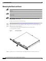
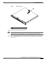
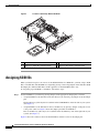
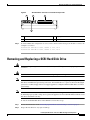
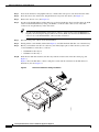
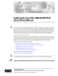
Installing Hard Disk Drives in the Cisco Wide
Area Application Engine 611
Product Numbers: DISK-611SC-144GB=, DISK-611SC-300GB=
This publication provides basic instructions for installing SCSI hard disk drive options in the Wide Area
Application Engine 611 (WAE-611). These instructions are intended for experienced technicians.
Contents
This publication contains the following sections:
Note
•
Safety Overview, page 1
•
Introduction, page 3
•
Removing the Bezel and Cover, page 4
•
Assigning SCSI IDs, page 6
•
Removing and Replacing a SCSI Hard Disk Drive, page 7
•
Replacing the Cover and Bezel and Completing the Installation, page 9
•
Obtaining Documentation, page 10
•
Cisco Product Security Overview, page 10
•
Obtaining Technical Assistance, page 11
For translations of the warnings in this publication, see the “Related Documentation” section on page 3.
Safety Overview
Safety warnings appear throughout this publication in procedures that may harm you if performed
incorrectly. A warning symbol precedes each warning statement.
Corporate Headquarters:
Cisco Systems, Inc., 170 West Tasman Drive, San Jose, CA 95134-1706 USA
© 2005 Cisco Systems, Inc. All rights reserved.
Safety Overview
Warning
IMPORTANT SAFETY INSTRUCTIONS
This warning symbol means danger. You are in a situation that could cause bodily injury. Before you
work on any equipment, be aware of the hazards involved with electrical circuitry and be familiar
with standard practices for preventing accidents. Use the statement number provided at the end of
each warning to locate its translation in the translated safety warnings that accompanied this
device. Statement 1071
SAVE THESE INSTRUCTIONS
Protecting Against Electrostatic Discharge
Static electricity can harm delicate components inside the device. To prevent static damage, discharge
static electricity from your body before you touch any of your system’s electronic components. You can
do so by touching an unpainted metal surface on the chassis.
You can also take the following steps to prevent damage from electrostatic discharge (ESD):
•
When unpacking a static-sensitive component from its shipping carton, do not remove the
component from the antistatic packing material until you are ready to install the component in your
system. Just before unwrapping the antistatic packaging, be sure to discharge static electricity from
your body.
•
When transporting a sensitive component, first place it in an antistatic container or packaging.
•
Handle all sensitive components in a static-safe area. If possible, use antistatic floor pads and
workbench pads.
Rack Installation Safety Guidelines
Before installing your device in a rack, review the following guidelines:
•
Two or more people are required to install the device in a rack.
•
Ensure that the room air temperature is below 95°F (35°C).
•
Do not block any air vents; usually 6 inches (15 cm) of space provides proper airflow.
•
Plan the device installation starting from the bottom of the rack.
•
Install the heaviest device in the bottom of the rack.
•
Do not extend more than one device out of the rack at the same time.
•
Remove the rack doors and side panels to provide easier access during installation.
•
Connect the device to a properly grounded outlet.
•
Do not overload the power outlet when installing multiple devices in the rack.
•
Do not place any object weighing more than 110 lb (50 kg) on top of rack-mounted devices.
Installing Hard Disk Drives in the Cisco Wide Area Application Engine 611
2
78-17404-01
Introduction
Introduction
The WAE-611 supports two 1-inch (2.54-cm) slim 3.5-inch (8.89-cm) low voltage differential (LVD)
hard disk drives. The WAE-611 requires SCSI hard disk drives.
Warning
Only trained and qualified personnel should be allowed to install, replace, or service this equipment.
Statement 1030
Required Tools
The following tools are required to perform the hard disk drive installation:
•
Antistatic mat or foam pad to support and protect the removed hard disk drive
•
Your own ESD-prevention equipment or the disposable grounding wrist strap included with all
upgrade kits, field-replaceable units (FRUs), and spares
Caution
Always use an ESD wrist strap when handling modules or coming into contact with internal components.
Warning
Blank faceplates and cover panels serve three important functions: they prevent exposure to
hazardous voltages and currents inside the chassis; they contain electromagnetic interference (EMI)
that might disrupt other equipment; and they direct the flow of cooling air through the chassis. Do not
operate the system unless all cards, faceplates, front covers, and rear covers are in place. Statement
1029
Warning
The safety cover is an integral part of the product. Do not operate the unit without the safety cover
installed. Operating the unit without the cover in place will invalidate the safety approvals and pose
a risk of fire and electrical hazards. Statement 117
Related Documentation
Use this publication in conjunction with the following hardware documentation:.
Note
•
Cisco Wide Area Application Engine 511 and 611 Hardware Installation Guide
•
Regulatory Compliance and Safety Information for the Cisco Content Networking Product Series
To access these publications on Cisco.com, see the “Obtaining Documentation” section on page 10.
Installing Hard Disk Drives in the Cisco Wide Area Application Engine 611
78-17404-01
3
Removing the Bezel and Cover
Removing the Bezel and Cover
Warning
Before working on a system that has an on/off switch, turn OFF the power and unplug the power cord.
Statement 1
Warning
Do not work on the system or connect or disconnect cables during periods of lightning activity.
Statement 1001
Warning
When installing or replacing the unit, the ground connection must always be made first and
disconnected last. Statement 1046
To remove the bezel and cover, follow these steps:
Step 1
Review the information in the “Protecting Against Electrostatic Discharge” section on page 2.
Step 2
Power down the device and all attached devices. Disconnect the power cord and all external cables.
Step 3
Remove the bezel as shown in Figure 1.
a.
Press the release tabs on the bezel and pull the bezel away from the chassis.
b.
Store the bezel in a safe place.
Removing the Bezel
151560
Figure 1
Step 4
To remove the cover, loosen the captive screw (labeled 1 in Figure 2) on the rear of the cover.
Installing Hard Disk Drives in the Cisco Wide Area Application Engine 611
4
78-17404-01
Removing the Bezel and Cover
Figure 2
Removing the Cover
151559
1
1
Step 5
Captive screw
Slide the cover back. Lift it up and off the device.
Caution
For proper cooling and airflow, replace the cover before turning on the device. Operating the device for
extended periods (over 30 minutes) with the cover removed might damage device components.
Step 6
Before you begin working inside the chassis, familiarize yourself with the location of the components
that you will be handling. Figure 3 shows the front of the chassis and the location of the drive bays
behind the bezel.
Installing Hard Disk Drives in the Cisco Wide Area Application Engine 611
78-17404-01
5
Assigning SCSI IDs
Figure 3
Location of Drive Bays Behind the Bezel
151556
1
4
2
3
1
CD-ROM drive
2
Flash memory card
3
Drive bay 1 (right side of chassis front)
4
Drive bay 0 (left side of chassis front)
Assigning SCSI IDs
When you install or replace one or more of the SCSI disk drives in a WAE-611, you must assign a SCSI
ID to each disk drive. The SCSI IDs are assigned by placing or removing jumpers on the disk drive SCSI
ID jumper pins. The hard disk drives in this appliance use the SCSI IDs 0 and 1 only.
To assign the proper SCSI ID to a disk drive, follow these steps:
Step 1
Set the SCSI IDs for your drive by placing jumpers on the appropriate jumper pins, as follows:
•
Assign SCSI ID 0 to the disk drive in the first drive bay by removing any jumpers from the jumper
pins.
The first drive bay (drive bay 0) is located below the CD-ROM drive on the left side of your system.
(See Figure 3.)
•
Assign SCSI ID 1 to the disk drive in the second drive bay by placing a jumper on the pins closest
to the power connector. Figure 4 shows the jumper placement for SCSI ID 1.
The second drive bay (drive bay 1) is located below the flash memory card on the right side of your
system. (See Figure 3.)
Figure 4 shows the connector end of the hard disk drive and the location of the jumper pins.
Installing Hard Disk Drives in the Cisco Wide Area Application Engine 611
6
78-17404-01
Removing and Replacing a SCSI Hard Disk Drive
Figure 4
Hard Disk Drive Connectors and SCSI ID Jumper Pins
2
3
151557
1
4
Step 2
1
Power connector
2
Jumper pins
3
SCSI connector
4
Jumper placement for SCSI ID 1
To check whether the configuration is correct, refer to the boot time messages on the device console. An
example is as follows:
Attached scsi disk sda at scsi0, channel 0, id 0, lun 0
Attached scsi disk sdb at scsi0, channel 0, id 1, lun 0
Removing and Replacing a SCSI Hard Disk Drive
Warning
Before working on a system that has an on/off switch, turn OFF the power and unplug the power cord.
Statement 1
Warning
Read the installation instructions before connecting the system to the power source. Statement 1004
Note
All hard disk drives that you use in the WAE should have the same throughput speed rating. Mixing hard
disk drives with different speed ratings will cause all hard disk drives to operate at the lower throughput
speed. Cisco technical support does not support appliances configured with hard disk drives of mixed
speed ratings.
Note
The WAE-611 must have two hard disk drives. This system is not supported with a single hard disk drive.
To maintain proper system cooling, do not operate the appliance for more than 10 minutes without a hard
disk drive installed in each bay.
To install a SCSI hard disk drive in the WAE-611, follow these steps:
Step 1
Review the information in the “Protecting Against Electrostatic Discharge” section on page 2.
Step 2
Inspect the new drive for any signs of damage.
Installing Hard Disk Drives in the Cisco Wide Area Application Engine 611
78-17404-01
7
Removing and Replacing a SCSI Hard Disk Drive
Step 3
Power down the device and peripheral devices, and disconnect the power cord and all external cables.
Step 4
Press the release tabs on the bezel, and pull the bezel away from the chassis. (See Figure 1.)
Step 5
Remove the chassis cover. (See Figure 2.)
Step 6
To remove the hard disk drive in either drive bay, work from inside the chassis and disconnect the SCSI
cable from the hard disk drive by using your thumbs to work the cable connector out of the drive
connector. Do not pull directly on the cable itself.
Tip
To remove the hard disk drive in the first bay (the bay on the left below the CD-ROM drive),
begin by disconnecting the integrated drive electronics (IDE) cable from the CD-ROM drive for
easier access to the hard disk drive connectors that are below it.
Step 7
Disconnect the power cable from the hard disk drive.
Step 8
Gently pull the carrier handle (labeled 6 in Figure 5), and slide the hard disk drive out of the drive bay.
Step 9
Before you install the new drive in a drive bay, check the jumper pins to make sure that you have the
correct SCSI ID set on the drive, as follows:
Step 10
•
SCSI ID 0 for drive bay 0
•
SCSI ID 1 for drive bay 1
Slide the new disk drive back into the drive bay with the circuit board on the drive facing up. (See
Figure 3.)
Figure 5 shows the disk drive connector and pin locations and the orientation of the disk drives for
installation. (See also Figure 3.)
Figure 5
Disk Drive Orientation During Installation
1
2
4
6
5
151557
3
Installing Hard Disk Drives in the Cisco Wide Area Application Engine 611
8
78-17404-01
Replacing the Cover and Bezel and Completing the Installation
1
SCSI connector
2
Jumper pins
3
Power connector
4
Circuit board facing up
5
Drive carrier
6
Carrier handle
Step 11
Connect the power and SCSI cables to the drive. If you disconnected the IDE cable to the CD-ROM,
reconnect it.
Step 12
Make sure that your cables are lying flat inside the chassis, so that you do not shear them when you
replace the chassis cover.
Replacing the Cover and Bezel and Completing the Installation
Warning
To prevent bodily injury when mounting or servicing this unit in a rack, you must take special
precautions to ensure that the system remains stable. The following guidelines are provided to
ensure your safety:
•
This unit should be mounted at the bottom of the rack if it is the only unit in the rack.
•
When mounting this unit in a partially filled rack, load the rack from the bottom to the top with the heaviest
component at the bottom of the rack.
•
If the rack is provided with stabilizing devices, install the stabilizers before mounting or servicing the unit in
the rack. Statement 1006
Warning
This unit is intended for installation in restricted access areas. A restricted access area is where
access can only be gained by service personnel through the use of a special tool, lock and key, or
other means of security, and is controlled by the authority responsible for the location. Statement 37
Warning
This equipment must be grounded. Never defeat the ground conductor or operate the equipment in the
absence of a suitably installed ground conductor. Contact the appropriate electrical inspection
authority or an electrician if you are uncertain that suitable grounding is available. Statement 1024
Warning
When installing or replacing the unit, the ground connection must always be made first and
disconnected last. Statement 1046
Installing Hard Disk Drives in the Cisco Wide Area Application Engine 611
78-17404-01
9
Obtaining Documentation
To complete your installation, follow these steps:
Step 1
Install the cover. Place it into position, slide it forward, and then tighten the captive screw (labeled 1 in
Figure 2).
Caution
Before sliding the cover forward, make sure that the cover will properly engage the ledge at the front of
the device.
Step 2
Install the bezel, as follows:
a.
Align the hooks on the bottom of the bezel with the device.
b.
Press the bezel toward the device until it clicks into place.
Step 3
Install the device in the rack. See the Cisco Wide Area Application Engine 511 and 611 Hardware
Installation Guide for instructions.
Step 4
Connect all external cables and the power cord to the device, and then plug the power cord into a properly
grounded electrical outlet.
Obtaining Documentation
Cisco documentation and additional literature are available on Cisco.com. Cisco also provides several
ways to obtain technical assistance and other technical resources.
You can access the most current Cisco documentation at this URL:
http://www.cisco.com/techsupport
You can access the Cisco website at this URL:
http://www.cisco.com
You can access international Cisco websites at this URL:
http://www.cisco.com/public/countries_languages.shtml
Cisco Product Security Overview
Cisco provides a free online Security Vulnerability Policy portal at this URL:
http://www.cisco.com/en/US/products/products_security_vulnerability_policy.html
From this site, you can perform these tasks:
•
Report security vulnerabilities in Cisco products.
•
Obtain assistance with security incidents that involve Cisco products.
•
Register to receive security information from Cisco.
A current list of security advisories and notices for Cisco products is available at this URL:
http://www.cisco.com/go/psirt
Installing Hard Disk Drives in the Cisco Wide Area Application Engine 611
10
78-17404-01
Obtaining Technical Assistance
If you prefer to see advisories and notices as they are updated in real time, you can access a Product
Security Incident Response Team Really Simple Syndication (PSIRT RSS) feed from this URL:
http://www.cisco.com/en/US/products/products_psirt_rss_feed.html
Reporting Security Problems in Cisco Products
Cisco is committed to delivering secure products. We test our products internally before we release them,
and we strive to correct all vulnerabilities quickly. If you think that you might have identified a
vulnerability in a Cisco product, contact PSIRT:
•
Emergencies — [email protected]
An emergency is either a condition in which a system is under active attack or a condition for which
a severe and urgent security vulnerability should be reported. All other conditions are considered
nonemergencies.
•
Nonemergencies — [email protected]
In an emergency, you can also reach PSIRT by telephone:
Tip
•
1 877 228-7302
•
1 408 525-6532
We encourage you to use Pretty Good Privacy (PGP) or a compatible product to encrypt any sensitive
information that you send to Cisco. PSIRT can work from encrypted information that is compatible with
PGP versions 2.x through 8.x.
Never use a revoked or an expired encryption key. The correct public key to use in your correspondence
with PSIRT is the one linked in the Contact Summary section of the Security Vulnerability Policy page
at this URL:
http://www.cisco.com/en/US/products/products_security_vulnerability_policy.html
The link on this page has the current PGP key ID in use.
Obtaining Technical Assistance
Cisco Technical Support provides 24-hour-a-day award-winning technical assistance. The Cisco
Technical Support & Documentation website on Cisco.com features extensive online support resources.
In addition, if you have a valid Cisco service contract, Cisco Technical Assistance Center (TAC)
engineers provide telephone support. If you do not have a valid Cisco service contract, contact your
reseller.
Cisco Technical Support & Documentation Website
The Cisco Technical Support & Documentation website provides online documents and tools for
troubleshooting and resolving technical issues with Cisco products and technologies. The website is
available 24 hours a day, at this URL:
http://www.cisco.com/techsupport
Installing Hard Disk Drives in the Cisco Wide Area Application Engine 611
78-17404-01
11
Obtaining Technical Assistance
Access to all tools on the Cisco Technical Support & Documentation website requires a Cisco.com user
ID and password. If you have a valid service contract but do not have a user ID or password, you can
register at this URL:
http://tools.cisco.com/RPF/register/register.do
Note
Use the Cisco Product Identification (CPI) tool to locate your product serial number before submitting
a web or phone request for service. You can access the CPI tool from the Cisco Technical Support &
Documentation website by clicking the Tools & Resources link under Documentation & Tools. Choose
Cisco Product Identification Tool from the Alphabetical Index drop-down list, or click the Cisco
Product Identification Tool link under Alerts & RMAs. The CPI tool offers three search options: by
product ID or model name; by tree view; or for certain products, by copying and pasting show command
output. Search results show an illustration of your product with the serial number label location
highlighted. Locate the serial number label on your product and record the information before placing a
service call.
Submitting a Service Request
Using the online TAC Service Request Tool is the fastest way to open S3 and S4 service requests. (S3
and S4 service requests are those in which your network is minimally impaired or for which you require
product information.) After you describe your situation, the TAC Service Request Tool provides
recommended solutions. If your issue is not resolved using the recommended resources, your service
request is assigned to a Cisco engineer. The TAC Service Request Tool is located at this URL:
http://www.cisco.com/techsupport/servicerequest
For S1 or S2 service requests or if you do not have Internet access, contact the Cisco TAC by telephone.
(S1 or S2 service requests are those in which your production network is down or severely degraded.)
Cisco engineers are assigned immediately to S1 and S2 service requests to help keep your business
operations running smoothly.
To open a service request by telephone, use one of the following numbers:
Asia-Pacific: +61 2 8446 7411 (Australia: 1 800 805 227)
EMEA: +32 2 704 55 55
USA: 1 800 553-2447
For a complete list of Cisco TAC contacts, go to this URL:
http://www.cisco.com/techsupport/contacts
Installing Hard Disk Drives in the Cisco Wide Area Application Engine 611
12
78-17404-01
Obtaining Technical Assistance
Definitions of Service Request Severity
To ensure that all service requests are reported in a standard format, Cisco has established severity
definitions.
Severity 1 (S1)—Your network is “down,” or there is a critical impact to your business operations. You
and Cisco will commit all necessary resources around the clock to resolve the situation.
Severity 2 (S2)—Operation of an existing network is severely degraded, or significant aspects of your
business operation are negatively affected by inadequate performance of Cisco products. You and Cisco
will commit full-time resources during normal business hours to resolve the situation.
Severity 3 (S3)—Operational performance of your network is impaired, but most business operations
remain functional. You and Cisco will commit resources during normal business hours to restore service
to satisfactory levels.
Severity 4 (S4)—You require information or assistance with Cisco product capabilities, installation, or
configuration. There is little or no effect on your business operations.
Installing Hard Disk Drives in the Cisco Wide Area Application Engine 611
78-17404-01
13
Obtaining Technical Assistance
This document is to be used in conjunction with the documents listed in the “Related Documentation” section.
CCVP, the Cisco logo, and the Cisco Square Bridge logo are trademarks of Cisco Systems, Inc.; Changing the Way We Work, Live, Play, and Learn is a
service mark of Cisco Systems, Inc.; and Access Registrar, Aironet, BPX, Catalyst, CCDA, CCDP, CCIE, CCIP, CCNA, CCNP, CCSP, Cisco, the Cisco
Certified Internetwork Expert logo, Cisco IOS, Cisco Press, Cisco Systems, Cisco Systems Capital, the Cisco Systems logo, Cisco Unity,
Enterprise/Solver, EtherChannel, EtherFast, EtherSwitch, Fast Step, Follow Me Browsing, FormShare, GigaDrive, HomeLink, Internet Quotient, IOS,
iPhone, IP/TV, iQ Expertise, the iQ logo, iQ Net Readiness Scorecard, iQuick Study, LightStream, Linksys, MeetingPlace, MGX, Networking Academy,
Network Registrar, PIX, ProConnect, ScriptShare, SMARTnet, StackWise, The Fastest Way to Increase Your Internet Quotient, and TransPath are
registered trademarks of Cisco Systems, Inc. and/or its affiliates in the United States and certain other countries.
All other trademarks mentioned in this document or Website are the property of their respective owners. The use of the word partner does not imply a
partnership relationship between Cisco and any other company. (0709R)
© 2006 Cisco Systems, Inc. All rights reserved.
Printed in the USA on recycled paper containing 10% postconsumer waste.
Installing Hard Disk Drives in the Cisco Wide Area Application Engine 611
14
78-17404-01